Advertisement
Quick Links
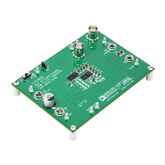
DESCRIPTION
Demonstration circuit 2543B is a high efficiency, high
density, open loop charge pump (inductorless) DC/DC
converter. This demo board is a voltage divider which
achieves a 2:1 step-down ratio from an input voltage from
36V to 60V. The output voltage is a fixed ratio of half of the
input voltage (V
IN
This demo board has the option to deliver a 20A maximum
load with the addition of 15 chip capacitors. See Figure 8
and Figure 10 for the details.
The DC2543B provides a very high efficiency solution of
98.7% when converting 48V
in Figure 3. When configured for a 20A output, an effi-
ciency of up to 98.4% is achievable for a 48V
at 20A as shown in Figure 8.
The demo board features the
voltage high power switched capacitor/charge pump
controller in a 4mm × 5mm QFN package. Please see
LTC7820 data sheet for more detailed information.
PERFORMANCE SUMMARY
PARAMETER
Input Voltage Range
Output Voltage, V
OUT
Maximum Output Current, I
Typical Efficiency
Peak Efficiency
Switching Frequency
NOTE: DC2543B demo board includes a Schottky diode added across the output. This manual describes the demo
board entitled "Demo Circuit 2543B." The DC2543B replaces the DC2543A.
Arrow.com.
Downloaded from
/2) and can supply a 10A load current.
to 24V
at 10A as shown
IN
OUT
LTC
7820, a fixed ratio high
®
CONDITION
V
= 36 to 60V, I
IN
V
= 36 to 60V, V
OUT
IN
V
= 48V, V
IN
V
= 48V, V
IN
DEMO MANUAL DC2543B
High Efficiency, Charge Pump
The DC2543B needs to be powered on with no load cur-
rent or a very small load current (less than 50mA) with
the default setup. Large load current can be applied after
V
is established. The board offers a disconnect FET
O
option which is controlled by the LTC7820 FAULT pin
to disconnect the load during startup as shown in the
schematic. Please refer to "Voltage Divider Prebalance
Before Switching" section in the LTC7820 data sheet for
more details regarding the startup of the voltage divider.
The board also features some protection functions
such as overcurrent and thermal shutdown to make it a
reliable solution.
to 24V
Design files for this circuit board are available.
IN
OUT
All registered trademarks and trademarks are the property of their respective owners.
Specifications are at T
= 25°C
A
= 0A to 10A
OUT
= V
/2
OUT
IN
= 24V, I
= 10A
OUT
OUT
= 24V
OUT
LTC7820EUFD
DC/DC Converter
VALUE
36V to 60V
V
/ 2
IN
10A
98.7%
99%
200kHz
Rev. 0
1
Advertisement

Related Manuals for Linear ANALOG DEVICES DC2543B


Summary of Contents for Linear ANALOG DEVICES DC2543B
- Page 1 DEMO MANUAL DC2543B LTC7820EUFD High Efficiency, Charge Pump DC/DC Converter DESCRIPTION Demonstration circuit 2543B is a high efficiency, high The DC2543B needs to be powered on with no load cur- density, open loop charge pump (inductorless) DC/DC rent or a very small load current (less than 50mA) with converter.
-
Page 2: Quick Start Procedure
DEMO MANUAL DC2543B QUICK START PROCEDURE Demonstration circuit 2543B is easy to set up to evaluate Notes: the performance of the LTC7820. Refer to Figure 1 for 1. When measuring the output or input voltage ripple, the proper measurement equipment setup and follow the do not use the long ground lead on the oscilloscope procedure below. - Page 3 DEMO MANUAL DC2543B QUICK START PROCEDURE – – – LOAD – – 36V to 60V DC2543B F01 Figure 1. Proper Measurement Equipment Setup Note: It is recommended to set the electronic load in CR (constant resistance) mode for evaluation of the DC2543B board. Some electronic loads draw negative current in CC (constant current) mode when evaluating the output overcurrent protection feature of DC2543B, which can violate the absolute maximum voltage rating –0.3V for V pin.
- Page 4 DEMO MANUAL DC2543B QUICK START PROCEDURE 24.6 24.4 24.2 24.0 23.8 23.6 23.4 23.2 23.0 OUTPUT LOAD CURRENT (A) OUTPUT LOAD CURRENT (A) DC2543B F04 DC2543B F03 Figure 3. Efficiency vs Load Current at V = 48V, Figure 4. Load Regulation for 10A Design = 24V, f = 200kHz at V...
- Page 5 DEMO MANUAL DC2543B QUICK START PROCEDURE 24.6 24.4 24.2 24.0 23.8 23.6 23.4 23.2 23.0 16 18 20 16 18 20 OUTPUT LOAD CURRENT (A) OUTPUT LOAD CURRENT (A) DC2543B F08 DC2543B F09 Figure 8. Efficiency vs Load Current at V = 48V, Figure 9.
-
Page 6: Parts List
DEMO MANUAL DC2543B PARTS LIST ITEM REFERENCE PART DESCRIPTION MANUFACTURER/PART NUMBER Required Circuit Components CAP , 33µF 20% 80V ELEC PANASONIC EEHZA1K330P C2, C3, C47, C49, C56, C57, C58, C59 CAP , 1210 2.2µF 10% 100V X7R MURATA GRM32DR72A225KA12 C4, C5, C15, C126 CAP , 0603 0.1µF 10% 100V X7R MURATA GRM188R72A104KA35D C6, C7... - Page 7 DEMO MANUAL DC2543B PARTS LIST Additional Demo Board Circuit Components C10-C14, C16, C33, C34, C35, C36, CAPACITOR, OPT C60-C64, C51, C77 C30-C32, C22-C25, C69-C72, C127 Q2, Q4, Q5,Q8 OPT MOSFET, OPT R6, R19, R2, R36, R8, R11, R12, RESISTOR, OPT R20, R34, R35, R60 Hardware: For Demo Board Only E1, E2, E6-E8, E10, E12, E14, E15...
-
Page 8: Schematic Diagram
DEMO MANUAL DC2543B SCHEMATIC DIAGRAM Rev. 0 Arrow.com. Arrow.com. Arrow.com. Arrow.com. Arrow.com. Arrow.com. Arrow.com. Arrow.com. Downloaded from Downloaded from Downloaded from Downloaded from Downloaded from Downloaded from Downloaded from Downloaded from... - Page 9 DEMO MANUAL DC2543B SCHEMATIC DIAGRAM Rev. 0 Information furnished by Analog Devices is believed to be accurate and reliable. However, no responsibility is assumed by Analog Devices for its use, nor for any infringements of patents or other rights of third parties that may result from its use. Specifications subject to change without notice.
- Page 10 DEMO MANUAL DC2543B ESD Caution ESD (electrostatic discharge) sensitive device. Charged devices and circuit boards can discharge without detection. Although this product features patented or proprietary protection circuitry, damage may occur on devices subjected to high energy ESD. Therefore, proper ESD precautions should be taken to avoid performance degradation or loss of functionality. Legal Terms and Conditions By using the evaluation board discussed herein (together with any tools, components documentation or support materials, the “Evaluation Board”), you are agreeing to be bound by the terms and conditions set forth below (“Agreement”) unless you have purchased the Evaluation Board, in which case the Analog Devices Standard Terms and Conditions of Sale shall govern.
Need help?
Do you have a question about the ANALOG DEVICES DC2543B and is the answer not in the manual?
Questions and answers