Table of Contents
Advertisement
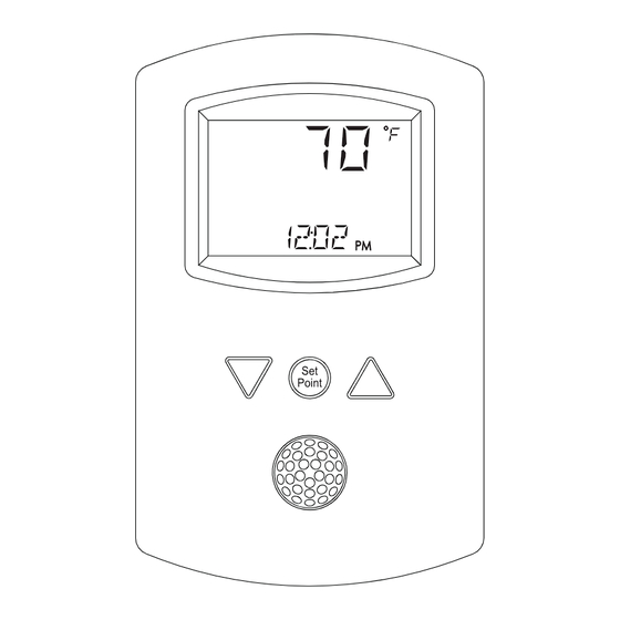
STE-8001 and STE-8201 sensors
Section 1
Specifications ...........................................................................................................................4
Safety considerations .............................................................................................................6
Section 2
Installing STE-8000 sensors
Planning for motion sensing .................................................................................................7
Rough-in preparation ............................................................................................................8
Installing the sensors ..............................................................................................................8
Maintenance ............................................................................................................................9
Section 3
Operating the STE-8000 .......................................................................................................11
Changing setpoints ...............................................................................................................12
The commissioning sequence .............................................................................................14
Enter the commissioning mode ..........................................................................................14
Setting up network communications .................................................................................15
Box options ............................................................................................................................16
Setting commissioning setpoints ........................................................................................20
Setting the airflow setpoints ...............................................................................................23
Balancing airflow ..................................................................................................................27
Advanced options ................................................................................................................31
Revision A
Installation Guide
7O
12O2
Set
Point
Advertisement
Table of Contents

Related Manuals for KMC Controls STE-8001


Summary of Contents for KMC Controls STE-8001
-
Page 1: Table Of Contents
STE-8001 and STE-8201 sensors Installation Guide 12O2 Point Section 1 Introduction to STE-8000 sensors Specifications ...........................4 Safety considerations ......................6 Section 2 Installing STE-8000 sensors Planning for motion sensing ....................7 Rough-in preparation ......................8 Installing the sensors ......................8 Maintenance ..........................9 Section 3 User functions Operating the STE-8000 .......................11... - Page 2 Disclaimer The material in this manual is for information purposes only. The contents and the product it describes are subject to change without notice. KMC Controls, Inc. makes no representations or warranties with respect to this manual. In no event shall KMC Controls, Inc.
- Page 3 SECTION 1 Introduction to STE-8000 sensors This section provides a description of the KMC Controls STE-8001 and STE-8201 wall sensors. It also introduces safety information. Review this material before installing or operating the sensors. Models STE-8001 and STE-8201 are wall-mounted, temperature sensor for use with KMC BAC-8000 series VAV controllers.
-
Page 4: Introduction To Ste-8000 Sensors Specifications
Introduction to STE-8000 sensors KMC Controls Specifications Specifications Display Multifunctional LCD 1.88 x 1.25 in. (48 x 32 mm) Compatibility BAC-8000 series VAV controllers Controller Connection Eight-wire RJ-45 modular jack Connector type Cable type and length Standard Ethernet cable up to 75 feet (22.9 meters) - Page 5 STE-8001 and STE-8201 sensors Introduction to STE-8000 sensors Specifications Motion sensor range Model STE-8201 only Detector type Passive infrared Range 33 feet (10 meters). See diagrams 10 m 10 m 32.8 ft 32.8 ft 46.5° 0° 0° 55° 10 m 10 m 32.8 ft...
-
Page 6: Safety Considerations
Temperature and motion STE-8201 Safety considerations KMC Controls assumes the responsibility for providing you a safe product and safety guidelines during its use. Safety means protection to all individuals who install, operate, and service the equipment as well as protection of the equipment itself. -
Page 7: Planning For Motion Sensing
SECTION 2 Installing STE-8000 sensors This section provides important instructions and guidelines for installing the STE-8000 series sensors. Carefully review this information before installing the controllers. Installing the sensors includes the following topics that are covered in this section. Planning for motion sensing on page 7 ◆... -
Page 8: Rough-In Preparation
Installing STE-8000 sensors KMC Controls Rough-in preparation False detections may be triggered by: ◆ The temperature inside the detection range suddenly changes because of the entry of cold or warm air from an air-conditioning or heating unit. ◆ The sensor being directly exposed to sunlight, an incandescent light, or other source of far-infrared rays. -
Page 9: Maintenance
STE-8001 and STE-8201 sensors Installing STE-8000 sensors Maintenance 4. Insert the Ethernet cable coming from the base into the sensor. 5. Place the top of the sensor over the top of the mounting base and swing it down over the Allen screw brackets. Be careful not to pinch any wiring. - Page 10 Installing STE-8000 sensors KMC Controls Maintenance Revision A...
-
Page 11: User Functions
SECTION 3 User functions This section covers topics for the end user in a facility. User functions are limited to changing the occupied temperature setpoints from the STE-8000. Operating the STE-8000 The functions are accessible through an STE-8000 series sensor. The functions are entered or changed using the buttons and display on the front of the STE-8000. -
Page 12: Changing Setpoints
User functions KMC Controls Changing setpoints Changing setpoints To enter or change the occupied setpoints you will need a Level 1 password. Enter occupied setpoints Procedure Steps STE display Starting display Start from the temperature display. 12S1 Enter the level one 1. -
Page 13: Commissioning Functions
SECTION 4 Commissioning functions This topics in this section are advanced topics for control technicians and engineers. The commissioning functions that are accessible through an STE-8000 series sensor are values and settings that are entered during the installation and commissioning of a VAV terminal unit. Typically these functions do not change after the installation and commissioning process. -
Page 14: The Commissioning Sequence
Commissioning functions KMC Controls The commissioning sequence commissioning sequence Set the commission functions in the following sequence. Enter the commissioning mode on page 14 Setting up network communications on page 15 Box options on page 16 Setting commissioning setpoints on page 20... -
Page 15: Setting Up Network Communications
STE-8001 and STE-8201 sensors Commissioning functions Setting up network communications Setting up network communications Set the network communication settings before placing a controller on the network. Setting network settings requires entering the Level 2 password which is described in the topic... -
Page 16: Box Options
Commissioning functions KMC Controls Box options Box options The box options set up the controller for the specific mechanical installation of the VAV terminal unit. Setting the box options requires entering the Level 2 password which is described in the topic... - Page 17 STE-8001 and STE-8201 sensors Commissioning functions Box options Procedure to set the box functions (Continued) Procedure Steps STE display Set the mode of 1. Press the buttons to choose REHT reheat for the one of the following reheat options. terminal unit None—Reheat is not enabled.
- Page 18 Commissioning functions KMC Controls Box options Procedure to set the box functions (Continued) Procedure Steps STE display Set the damper 1. Press the buttons to which DDIR direction to close direction to damper moves to close. CCW—The actuator turns counterclockwise to close the damper.
- Page 19 STE-8001 and STE-8201 sensors Commissioning functions Box options Procedure to set the box functions (Continued) Procedure Steps STE display Advance or exit 1. Press the buttons to select one of the following: • STPT , FLOW , or ADVC options •...
-
Page 20: Setting Commissioning Setpoints
Commissioning functions KMC Controls Setting commissioning setpoints Setting commissioning setpoints The commissioning setpoints set the operational parameters and limits for the VAV terminal unit. Setting configuration setpoints requires entering a Level 2 password which is described in the topic Enter the commissioning mode on... - Page 21 STE-8001 and STE-8201 sensors Commissioning functions Setting commissioning setpoints Procedure to set the commissioning setpoints (Continued) Procedure Steps STE display Set the occupied 1. Press the buttons to set the OCCL cooling setpoint occupied cooling setpoint. The setpoint will change in 0.5°...
- Page 22 Commissioning functions KMC Controls Setting commissioning setpoints Procedure to set the commissioning setpoints (Continued) Procedure Steps STE display Set the minimum 1. Press the buttons to set the DIFF temperature differential setpoint. The setpoint will change in 1° increments. differential 2.
-
Page 23: Setting The Airflow Setpoints
STE-8001 and STE-8201 sensors Commissioning functions Setting the airflow setpoints Setting the airflow setpoints The airflow setpoints configure the airflow limits for the VAV terminal unit. Setting the airflow setpoints requires entering a Level 2 password which is described in the topic... - Page 24 Commissioning functions KMC Controls Setting the airflow setpoints Procedure to set the airflow setpoints (Continued) Procedure Steps STE display Set the cooling 1. Press the buttons to set the MNCL minimum airflow minimum limit for cooling airflow. The setpoint will change in 1 CFM limit increments.
- Page 25 STE-8001 and STE-8201 sensors Commissioning functions Setting the airflow setpoints Procedure to set the airflow setpoints (Continued) Procedure Steps STE display Set the cooling 1. Press the buttons to set the MNCL minimum airflow minimum limit for cooling airflow. The setpoint will change in 1 CFM limit increments.
- Page 26 Commissioning functions KMC Controls Setting the airflow setpoints Procedure to set the airflow setpoints (Continued) Procedure Steps STE display Set the minimum 1. Press the buttons to set the MNC2 limit for indoor air minimum limit for ventilation quality ventilation airflow.
-
Page 27: Balancing Airflow
STE-8001 and STE-8201 sensors Commissioning functions Balancing airflow Balancing airflow The airflow balancing method described in this section requires a flow hood or other accurate method to measure airflow. The airflow balancing procedure requires entering the Level 2 password which is described in the topic... - Page 28 Commissioning functions KMC Controls Balancing airflow The airflow balancing procedure (Continued) Procedure Steps STE display The display begins flashing PMAX Measure and enter PMAX the actual and also displays the actual airflow maximum primary at the bottom. airflow Note: The airflow will attempt to stabilize...
- Page 29 STE-8001 and STE-8201 sensors Commissioning functions Balancing airflow The airflow balancing procedure (Continued) Procedure Steps STE display Advance or exit 1. Press the buttons to select one of the following: • SEC to balance the secondary VAV for dual duct systems •...
- Page 30 Commissioning functions KMC Controls Balancing airflow The airflow balancing procedure (Continued) Procedure Steps STE display The display begins flashing SMIN Measure and enter SMIN the actual and also displays the actual airflow minimum at the bottom. secondary airflow Note: The airflow displayed by the STE-8000 in this step is the actual, uncorrected airflow.
-
Page 31: Advanced Options
STE-8001 and STE-8201 sensors Commissioning functions Advanced options Advanced options The advanced options set up passwords and special features in the controller. Setting the advance options requires entering the Level 2 password which is described in the topic Enter the commissioning mode on page... - Page 32 Commissioning functions KMC Controls Advanced options Procedure to set the advanced options (Continued) Procedure Steps STE display Enter a new Note: Entering four zeros (0000) removes PSW2 Level 2 password the password. password 1. Press the buttons to change the first digit.
- Page 33 STE-8001 and STE-8201 sensors Commissioning functions Advanced options Procedure to set the advanced options (Continued) Procedure Steps STE display Advance or exit 1. Press the buttons to select ADVC one of the following: • STPT , FLOW , or BOX options •...
- Page 34 Commissioning functions KMC Controls Advanced options Revision A...
Need help?
Do you have a question about the STE-8001 and is the answer not in the manual?
Questions and answers