Arista 7800 Series Quick Start Manual
Modular data center switch
Hide thumbs
Also See for 7800 Series:
- Quick start manual (78 pages) ,
- Installation manual (10 pages) ,
- Quick start manual (56 pages)

Related Manuals for Arista 7800 Series


Summary of Contents for Arista 7800 Series
-
Page 1: Quick Start Guide
Quick Start Guide 7800 Series Modular Data Center Switch Arista Networks www.arista.com DOC-04133-01... - Page 2 © Copyright 2020 Arista Networks, Inc. The information contained herein is subject to change without notice. Arista Networks and the Arista logo are trademarks of Arista Networks, Inc in the United States and other countries. Other product or service names may be trademarks or service marks of others.
-
Page 3: Table Of Contents
Recommendations for power supply usage................19 Power Supply Redundancy ........................19 Connecting Supervisor Cables ......................20 Connecting Line Card Modules and Cables ..................23 Chapter 5 Configuring the Modular Switch ..............25 Appendix A Status Indicators...................27 24 February 2020iii Quick Start Guide: 7800 Series Modular Switches... - Page 4 Linecards .............................. 46 F.4.1 Removing Linecard ........................46 F.4.2 Removing Linecard Blank ......................47 F.4.3 Installing Linecard ........................47 Appendix G Regulatory Model Numbers .................49 Appendix H Taiwan RoHS Information ................51 24 February 2020Quick Start Guide: 7800 Series Modular Switches...
-
Page 5: Chapter 1 Overview
Inspect the packing list and confirm that you received all listed items. Compare the packing list with your 7800 Series Modular Switches purchase order. Appendix B provides a list of components included with the switch. -
Page 6: Safety Information
Aucune pièce réparable par l'utilisateur à l'intérieur. Confiez toute réparation à un technicien qualifié. Safety Information Refer to the Arista Networks document Safety Information and Translated Safety Warnings available at: https://www.arista.com/en/support/product-documentation Obtaining Technical Assistance Any customer, partner, reseller or distributor holding a valid Arista Service Contract can obtain... -
Page 7: Specifications
Chapter 1: Overview Specifications Specifications Table 1-1 lists the specifications of Arista Data Center modular switches covered by this guide. Table 1-1 Modular switch specifications DCS-7808 Height 16RU: 702 mm (27.64 inches) Width 441 mm (17.36 inches) maximum Depth 940 mm (37.01 inches) Weight 338.6 kg (745 lbs) fully... - Page 8 Note1: Includes typical power supply conversion inefficiency. Contact your local Sales Engineer for 7800 power calculator details. Note2: Power numbers given as Typical/Maximum or Typical/Hot/Maximum where Hot is defined as 40°C Sea Level. * Not N+N redundant power at worst case Temp/Elevation. Quick Start Guide: 7800 Series Modular Switches...
-
Page 9: Chapter 2 Preparation
Table 2-1 Clearance requirements and footprint dimensions Clearance Requirements Dimensions Switch DCS-7808 38.4 cm (15.1 in.) 102.1 cm (40.2 in.) 58.9 cm (23.2 in.) Note The PSU removal clearance (Front) is 62.5 cm (24.6 in.) Quick Start Guide: 7800 Series Modular Switches... - Page 10 The accessory kit provides the required mounting hardware for each switch. Power Requirements: • Arista switches require a minimum number of operating power supplies in all chassis, AC or DC, and for each power domain of switches with multiple power domains. Refer Chapter 4 for more details regarding your switch.
-
Page 11: Tools And Parts Required For Installation
Minimize handling of assemblies and components. • Keep replacement parts in their original static-free packaging. • Remove all plastic, foam, vinyl, paper, and other static-generating materials from the work area. • Use tools that do not create ESD. Quick Start Guide: 7800 Series Modular Switches... - Page 12 Electrostatic Discharge (ESD) Precautions Chapter 2: Preparation Quick Start Guide: 7800 Series Modular Switches...
-
Page 13: Chapter 3 Rack Mounting The Switch
To insert and secure the cradle assembly to the rack use the following steps. Step 1 Insert two screws loosely in the two front rack posts at the same level and two in the back two rack posts 3 RU above the front screws (Figure 3-1). Quick Start Guide: 7800 Series Modular Switches... - Page 14 Step 5 Slide the rear sliding rails back in so that they are flush with the back rack posts, the notches in the cradle engage behind the loosely mounted screws, and the bottom of the cradle is horizontal and level (Figure 3-3). Quick Start Guide: 7800 Series Modular Switches...
- Page 15 Chapter 3: Rack Mounting the Switch 7808 Rack Mounting Figure 3-3: Inserting the cradle Step 6 Release the clasp on the connector to rotate the left and right sides so they are vertical. (Figure 3-4). Quick Start Guide: 7800 Series Modular Switches...
- Page 16 Step 7 Secure the cradle to the rack posts using the eight remaining screws, two more in the front and 6 more in the back for a total of twelve screws. (Figure 3-5). Quick Start Guide: 7800 Series Modular Switches...
-
Page 17: Inserting The Switch Into The Rack
Step 1 Move the chassis to the rack using a mechanical lift (Figure 3-6). Note If modules are inserted in the chassis, use the lift carefully to avoid damaging any components. Step 2 Lift the chassis into the rack. Quick Start Guide: 7800 Series Modular Switches... - Page 18 (Figure 3-7). Note Additional screws depend on the device. The 7808 chassis requires nine. Figure 3-7: Secure the switch to the rack shelf Step 4 After completing the Four-Post Installation, proceed to Chapter Quick Start Guide: 7800 Series Modular Switches...
-
Page 19: Chapter 4 Cabling The Modular Switch
Chapter 4 Cabling the Modular Switch Cabling the Power Supplies Before you begin, refer to the Arista Networks document Compliance and Safety Guide available at: https://www.arista.com/en/support/product-documentation. Important! Power down the switch: Remove all power cords from the power inlets. Mettez le commutateur: Retirez tous les cordons d'alimentation des prises d'alimentation. -
Page 20: Cabling Chassis Ground
Important! Secondary Grounding wires, lugs and screws (M4 x 0.7) are not supplied. Secondaire à la terre, câbles, cosses et vis (M4 x 0.7) ne sont pas fournis. Figure 4-1: Chassis ground locations Quick Start Guide: 7800 Series Modular Switches... -
Page 21: Cabling The Ac Power Supplies
The LEDs on a PSU remain lit for a period of time even after you disconnect the power and remove the PSU from the chassis. They will eventually turn off in a short while. Note The PWR-D1-3041-AC-BLUE PSU uses 2x 220 V supply inputs and uses 2 APP Saf-D-Grid 400 connectors. Quick Start Guide: 7800 Series Modular Switches... -
Page 22: Cabling The Dc Power Supply
PWR-D1-3041-AC-BLUE 3000 W 200 to 240 VAC(nominal) 2x 16 A 2x 20 A 50/60 Hz (nominal) PWR-D2-3041-DC-BLUE 3000 W -48 V to -60 VDC, 70 A to 2x 70 A 2x 90 A Quick Start Guide: 7800 Series Modular Switches... -
Page 23: Power Supply Configurations
Most installations will have redundant, dual, independent power feeds. Each independent power feed will be referenced as A and B. • The recommended installation is to wire input_A and input_B of each supply to independent power feed (A or B). Quick Start Guide: 7800 Series Modular Switches... -
Page 24: Connecting Supervisor Cables
RJ-45 Ethernet management port PSU status LED Clock In SFP Ethernet management port Console (Serial) Port: • Connect to a PC with RJ-45 to DB-9 serial adapter cable. Default switch settings include: • 9600 baud Quick Start Guide: 7800 Series Modular Switches... - Page 25 The DCS-7808-SUP-D supervisor cards must be installed in one of the two slots designated for them in the DCS-7808 switch as shown in Figure 4-4. Figure 4-4: DCS 7808 Supervisor Slots Supervisor modules Power Supplies Extraction tool Line cards Quick Start Guide: 7800 Series Modular Switches...
- Page 26 • Connect to 10/100/1000 management network with RJ-45 cable. USB Port: • May be used for software or configuration updates. Clock Input Port: Port type is MCX connector, 2-5.5V, 50 ohm termination. • Quick Start Guide: 7800 Series Modular Switches...
-
Page 27: Connecting Line Card Modules And Cables
Flexion excessive peut endommager les câbles d'interface, en particulier les câbles optiques. Note You must ensure that any open slots for modules, power supplies, etc. are covered by the appropriate “blank” plates. Check with your local Arista Networks representative if you have questions. Quick Start Guide: 7800 Series Modular Switches... - Page 28 Connecting Line Card Modules and Cables Chapter 4: Cabling the Modular Switch Quick Start Guide: 7800 Series Modular Switches...
-
Page 29: Chapter 5 Configuring The Modular Switch
Chapter 5 Configuring the Modular Switch Arista switches ship from the factory in Zero Touch Provisioning (ZTP) mode. ZTP configures the switch without user intervention by downloading a startup configuration file or a boot script from a location specified by a DHCP server. To manually configure a switch, ZTP is bypassed. The initial configuration... - Page 30 Step 11 When the management port IP address is configured, use this command to access the switch from a host, using the address configured in step 9: ssh admin@192.0.2.8 Arista Networks User Manual Refer to the for complete switch configuration information. Quick Start Guide: 7800 Series Modular Switches...
-
Page 31: Appendix A Status Indicators
The system status indicator LEDs are shown in Figure A-1. Figure A-1: Supervisor 7800-SUP-D Locking mechanism Line card status LED RJ-45 Serial management port Supervisor status LED Fabric Module status LED USB Ports Quick Start Guide: 7800 Series Modular Switches... - Page 32 - no AC input, DC output, Over current or not enough PSUs present Supervisor active, Green Green Status: LC failure (one or more) Supervisor active, Green Green Status: FM failure (one or more) Quick Start Guide: 7800 Series Modular Switches...
-
Page 33: Line Card Module Indicators
The figures in Appendix E indicate the location of the LEDs on each line card. Figure A-2: Line card Status LED Line card status LED Port status LED Quick Start Guide: 7800 Series Modular Switches... -
Page 34: Fabric Module Status Indicators
Fabric Status LEDs are on fan-fabric modules. Appendix D displays the position of these modules on the rear of each switch. Figure A-3 displays fan status and fabric status LEDs on the switch. Quick Start Guide: 7800 Series Modular Switches... -
Page 35: Power Supply Status Indicators
Module operating normally Module failed Power Supply Status Indicators • PWR-D1-3041-AC-BLUE The power supply LEDs are on the power supply modules. Figure A-4 displays all the AC power supply modules supported on the 7808. Quick Start Guide: 7800 Series Modular Switches... - Page 36 DC power supply setup for LED status indicators. Table A-6 DC Power Supply Status LED states LED Name Power Supply Status Input_A Input_B Output Normal Operation Green Green Green No DC Input - Single PSU Quick Start Guide: 7800 Series Modular Switches...
- Page 37 Blinking Green Input_A Fail Yellow Green Green Input_B Fail Green Yellow Green Power Supply Fault Green Green Yellow Boot Loader Blinking 1. 1 Hz, 50% Duty Cycle. 2. 1 Hz, 50% Green, 50% Yellow. Quick Start Guide: 7800 Series Modular Switches...
- Page 38 Power Supply Status Indicators Appendix A: Status Indicators Quick Start Guide: 7800 Series Modular Switches...
-
Page 39: Appendix B Parts List
8-slot chassis (See Section B.2 Number of Power cords included Warning All provided power cables are for use only with Arista products. Câbles d’alimentation doivent être utilisés uniquement avec des produits de Arista Quick Start Guide: 7800 Series Modular Switches... -
Page 40: Parts Used In All Rack Mount Configurations
The following sections list the parts provided in the accessory kit for four-post rack mount installations. Table B-3 Four-Post rack mount parts Quantity Description Cradle assembly. Rack mounting screws. Figure B-1: Four-Post rack mount parts Quick Start Guide: 7800 Series Modular Switches... -
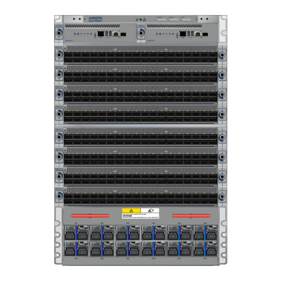
Page 41: Appendix C Front Panel
This appendix displays the front panel of all switches covered by this guide. Figure C-1: DCS-7808 front panel (fully populated) ESD attach point Supervisor modules Line card and Supervisor extraction tool Grounding locations Line card lock Power supplies Supervisor lock Line cards Quick Start Guide: 7800 Series Modular Switches... - Page 42 Appendix C: Front Panel Quick Start Guide: 7800 Series Modular Switches...
-
Page 43: Appendix D Rear Panel
Rear Panel This appendix displays the rear panel of all switches covered by this guide. Figure D-1: DCS-7808 rear panel (fully populated) Fabric module screw Chassis ground Fabric module release ESD attachment point Quick Start Guide: 7800 Series Modular Switches... - Page 44 Appendix D: Rear Panel Quick Start Guide: 7800 Series Modular Switches...
-
Page 45: Appendix E Line Cards
This appendix displays the line cards supported by modular switches covered by this guide. DCS-7800R3-48CQ-LC, DCS-7800R3K-48CQ-LC and DCS-7800R3KM-48CQ-LC Line card status LED Port status LEDs DCS-7800R3K-36P-LC Line card status LED Port status LEDs Quick Start Guide: 7800 Series Modular Switches... - Page 46 Appendix E: Line Cards Quick Start Guide: 7800 Series Modular Switches...
-
Page 47: Appendix F Maintenance And Field Replacement
Perform the following steps to remove an AC power supply. Step 1 Put on a grounded, anti-static ESD strap. Step 2 Unplug the cable(s) by squeezing the cable release. Up to two cables could be powering each PSU. Quick Start Guide: 7800 Series Modular Switches... -
Page 48: Removing Dc Power Supply
Supply) or removing a blank (Removing Power Supply Blank) from a power supply slot available on the switch. Perform the following steps to install a DC power supply. Step 1 Put on a grounded ESD strap. Quick Start Guide: 7800 Series Modular Switches... -
Page 49: Fabric And Fan Module (Fabric Module)
Step 6 Screw in the two Phillips screws. Step 7 Verify that the module is operating normally (Table A-4 on page 31). Step 8 Use the show environment cooling command to further verify normal operation. Quick Start Guide: 7800 Series Modular Switches... -
Page 50: Supervisor Module
Removing Linecard Perform the following steps to remove a linecard. Step 1 Put on a grounded, anti-static ESD strap. Step 2 Use the tools supplied (Appendix C) simultaneously on each end of the linecard. Quick Start Guide: 7800 Series Modular Switches... -
Page 51: Removing Linecard Blank
Step 4 Use the tools supplied (Appendix C) simultaneously on each end of the linecard to lock it in place. Step 5 Verify that the linecard is operating normally (Table A-2 on page 30). Quick Start Guide: 7800 Series Modular Switches... - Page 52 Linecards Appendix F: Maintenance and Field Replacement Quick Start Guide: 7800 Series Modular Switches...
-
Page 53: Appendix G Regulatory Model Numbers
This appendix lists the regulatory model numbers (RMNs), where applicable, for the product models for the switches described in this document. Table G-1 Regulatory Model Numbers and Product Numbers Regulatory Model Number (RMN) Product Number(s) DCS-7808 DCS-7808 Quick Start Guide: 7800 Series Modular Switches... - Page 54 Appendix G: Regulatory Model Numbers Quick Start Guide: 7800 Series Modular Switches...
-
Page 55: Appendix H Taiwan Rohs Information
Appendix H Taiwan RoHS Information This appendix provides Taiwan RoHS information for switches covered by this guide. For Taiwan BSMI RoHS Table, go to https://www.arista.com/assets/data/pdf/AristaBSMIRoHS.pdf. Quick Start Guide: 7800 Series Modular Switches... - Page 56 Appendix H: Taiwan RoHS Information Quick Start Guide: 7800 Series Modular Switches...
Need help?
Do you have a question about the 7800 Series and is the answer not in the manual?
Questions and answers