
Subscribe to Our Youtube Channel
Related Manuals for Arista 720D Series


Summary of Contents for Arista 720D Series
- Page 1 Quick Start Guide Ethernet Switch 720D Series CCS-720DP-48S CCS-720DP-24S CCS-720DT-48S CCS-720DT-24S CCS-720DF-48Y CCS-720DP-24ZS CCS-720DP-48ZS Arista Networks www.arista.com DOC-05297-05...
- Page 2 The trademarks, logos and service marks ("Marks") displayed in this documentation are the property of Arista Networks in the United States and other countries. Use of the Marks are subject to Arista Network Term of Use Policy, available at https:// www.arista.com/en/terms-of-use.
-
Page 3: Table Of Contents
Contents Contents Chapter 1: Overview................1 1.1 Scope............................1 1.2 Intended Audience........................1 1.3 Receiving and Inspecting the Equipment................2 1.4 Installation Process.........................2 1.5 Safety Information........................2 1.6 Obtaining Technical Assistance..................... 2 1.7 Product and Documentation Updates..................2 1.8 Specifications.......................... 3 Chapter 2: Preparation................7 2.1 Site Selection..........................7 2.2 Tools and Parts Required for Installation................7 2.3 Electrostatic Discharge (ESD) Precautions................ - Page 4 8.7 CCS-720DT-24S-2F......................28 8.8 CCS-720DT-24S-F........................28 8.9 CCS-720DT-48S-2R......................29 8.10 CCS-720DT-48S-R......................29 8.11 CCS-720DF-48Y-2F......................30 8.12 CCS-720DP-24ZS-2F......................30 8.13 CCS-720DP-24ZS-F......................31 8.14 CCS-720DP-48ZS-2F......................31 8.15 CCS-720DP-48ZS-F......................32 Chapter 9: Operating Mode Button............. 33 Chapter 10: Regulatory Model Numbers..........35 Appendix A: Screw Size Details............37 Appendix B: Class A EMC Statement..........
-
Page 5: Chapter 1: Overview
Chapter 1 Overview This Quick Start Guide (QSG) describes the specifications and installation details of Arista Ethernet Switch. This chapter includes the following topics: • Scope • Intended Audience • Receiving and Inspecting the Equipment • Installation Process • Safety Information •... -
Page 6: Receiving And Inspecting The Equipment
4. Connect the switch to the power source and network devices. 5. Configure the switch. Safety Information Refer to the Arista Networks document Safety Information and Translated Safety Warnings available at https://www.arista.com/en/support/product-documentation Obtaining Technical Assistance Any customer, partner, reseller or distributor holding a valid Arista Service Contract can obtain technical support in any of the following ways: •... -
Page 7: Specifications
Overview Specifications This section lists the specifications of Arista Ethernet Switch described in this guide. Table 1: Switch Specifications (Dimensions and Weights) Switch Size (W x H x D) Weight CCS-720DP-48S-2F 440 x 43.5 x 430 mm 6.73 kg (17.32 x 1.71 x 16.92 inches) (14.83 lbs) - Page 8 Switch Size (W x H x D) Weight CCS-720DP-24ZS-F 440 x 43.5 x 430 mm 5.8 kg (17.32 x 1.71 x 16.92 inches) (12.78 lbs) CCS-720DP-48ZS-2F 440 x 43.5 x 430 8 kg 17.32 x 1.71 x 16.92 inches 17.63 lbs CCS-720DP-48ZS-F 440 x 43.5 x 430 6.9 kg...
- Page 9 Overview Switch Input Power Rating CCS-720DP-24S-F 100 - 240V~, 6 - 3A, 50/60 Hz CCS-720DT-48S-2F 100 - 240V~, 1.2-0.6A, 50/60 Hz CCS-720DT-48S-F 100 - 240V~, 1.2-0.6A, 50/60 Hz CCS-720DT-48S-2R 100 - 240V~, 1.2-0.6A, 50/60 Hz CCS-720DT-48S-R 100 - 240V~, 1.2-0.6A, 50/60 Hz CCS-720DT-24S-2F 100 - 240V~, 1-0.5A, 50/60 Hz CCS-720DT-24S-F...
- Page 10 Table 5: Switch Specifications (System Configurations) PoE Ports Downlink Uplink Ports Airflow Power Ports Supply CCS-720DP-48S-2F 48x1G 4x10G SFP+ Front to rear 2 RJ45 CCS-720DP-48S-F 48x1G 4x10G SFP+ Front to rear 1 RJ45 CCS-720DP-24S-2F 24x1G 4x10G SFP+ Front to rear 2 RJ45 CCS-720DP-24S-F 24x1G...
-
Page 11: Chapter 2: Preparation
Chapter 2 Preparation This chapter describes the initial setup and preparation for installing the switch. This chapter includes the following topics: • Site Selection • Tools and Parts Required for Installation • Electrostatic Discharge (ESD) Precautions Site Selection The following criteria should be considered when selecting a site to install the switch: •... -
Page 12: Electrostatic Discharge (Esd) Precautions
Electrostatic Discharge (ESD) Precautions Observe these guidelines to avoid ESD damage when installing or servicing the switch. • Assemble or disassemble equipment only in a static-free work area. • Use a conductive work surface (such as an anti-static mat) to dissipate static charge. •... -
Page 13: Chapter 3: Mounting The Switch
Chapter 3 Mounting the Switch This chapter provides the instructions to mount the switch. This chapter includes the following topics: • Two-Post Rack Mount Two-Post Rack Mount This section describes instructions for two-post rack mounting the switch. To mount the switch in a rack, you need to assemble the mounting brackets to the chassis, then attach the brackets to the rack posts. -
Page 14: Inserting The Switch Into The Rack
3.1.2 Inserting the Switch into the Rack This section describes the steps to insert the switch into the rack. Figure 2: Inserting the Switch into the Rack Screw M4x25mm (screw is not included in the kit) L-bracket Note: For more information regarding the screw size, refer to Screw Size Details Note: For thermal purposes, make sure that there is 1RU clearance above the rack mount bracket. -
Page 15: Chapter 4: Grounding The Switch
Chapter 4 Grounding the Switch This section provides instructions for grounding the switch. Normally, the functional grounding of the switch is achieved through the DC input connection. If you would like to do additional grounding, follow the instructions below: Figure 3: Grounding the Switch Screw M4 (with washer) Solder terminal lug Grounding point... -
Page 16: Chapter 5: Status Indicators
Chapter 5 Status Indicators This section describes the front panel LED status of the device. LED Status Indicators... - Page 17 Table 6: LED Status LED Name LED State Device Status System Status LED No power or in the midst of a power cycle. Blinking Green System is powering up. Green The system is operating in a normal initialization sequence. Normal operations.
- Page 18 Status Indicators LED Name LED State Device Status Port PoE Mode LED PoE mode is not selected. (CCS-720DP-48S, Green Port LED is selected to indicate port PoE CCS-720DP-24S, status. CCS-720DP-24ZS, CCS-720DP-48ZS) Port Speed Mode LED Speed mode is not selected. Green Port LED is selected to indicate port speed.
- Page 19 Port LEDs Normal Mode PoE Mode Speed Mode Amber Port is software Green disabled...
-
Page 20: Chapter 6: Parts List
The following are the list of SKU numbers related to the respective product. Table 9: SKU and Product Details Product Description CCS-720DP-48S-2F Arista 720DP, 48x1G PoE, 4x10G SFP+ switch, front to rear air, two 950W AC CCS-720DP-48S-F Arista 720DP, 48x1G PoE, 4x10G SFP+ switch, front to rear air,... - Page 21 Product Description CCS-720DT-48S-F Arista 720DT, 48x1G, 4x10G SFP+ switch, front to rear air, one 100W AC CCS-720DT-48S-2R Arista 720DT, 48x1G, 4x10G SFP+ switch, rear to front air, two 100W AC CCS-720DT-48S-R Arista 720DT, 48x1G, 4x10G SFP+ switch, rear to front air, one...
-
Page 22: Chapter 7: Front Panel
Chapter 7 Front Panel This section describes the front panel of the Ethernet Switch. CCS-720DP-48S The CCS-720DP-48S front panel includes the following key components: Figure 4: CCS-720DP-48S Front Panel System Status LEDs RJ45 Ethernet Management Port USB Port Console Port Port LEDs 4x10G SFP+ Ports SFP+ Port LEDs... -
Page 23: Ccs-720Dp-24S
CCS-720DP-24S The CCS-720DP-24S front panel includes the following key components: Figure 5: CCS-720DP-24S Front Panel System Status LEDs RJ45 Ethernet Management Port USB Port Console Port Port LEDs 4x10G SFP+ Ports SFP+ Port LEDs 24x1G PoE Ports Mode Button Mode Status LEDs CCS-720DT-48S The CCS-720DT-48S front panel includes the following key components: Figure 6: CCS-720DT-48S Front Panel... -
Page 24: Ccs-720Dt-24S
Front Panel RJ45 Ethernet Management Port USB Port Console Port Port LEDs 4x10G SFP+ Ports SFP+ Port LEDs 48x1G PoE Ports Mode Button Mode Status LEDs CCS-720DT-24S The CCS-720DT-24S front panel includes the following key components: Figure 7: CCS-720DT-24S Front Panel System Status LEDs RJ45 Ethernet Management Port USB Port... -
Page 25: Ccs-720Df-48Y
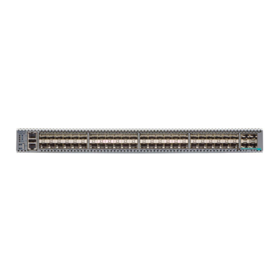
Mode status LEDs CCS-720DF-48Y The CCS-720DF-48Y front panel includes the following key components: Figure 8: CCS-720DF-48Y Front Panel System Status LEDs RJ45 Ethernet Management Port USB Port Console Port Port LEDs 4x25G SFP28 Ports SFP28 Port LEDs 48x1G PoE Ports Mode Button Mode Status LEDs... -
Page 26: Ccs-720Dp-24Zs
Front Panel CCS-720DP-24ZS The CCS-720DP-24ZS front panel includes the following key components: Figure 9: CCS-720DP-24ZS Front Panel System Status LEDs RJ45 Ethernet Management Port USB Port Console Port Port LEDs 4x10G SFP+ Ports SFP+ Port LEDs 24x1G PoE Ports Mode Button Mode Status LEDs CCS-720DP-48ZS The CCS-720DP-48ZS front panel includes the following key components:... - Page 27 RJ45 Ethernet Management Port USB Port Console Port Port LEDs 4x10G SFP+ Ports SFP+ Port LEDs 48x2.5G PoE Ports Mode Button Mode Status LEDs...
-
Page 28: Chapter 8: Rear Panel
Chapter 8 Rear Panel The section describes the rear panel of the Ethernet Switch. CCS-720DP-48S-2F The CCS-720DP-48S-2F rear panel includes the following key components: Figure 11: CCS-720DP-48S-2F Rear Panel Power Supply1 (PS1) Earth Grounding Point Fan1 Fan2 Fan3 Fan4 Power Supply2 (PS2) CCS-720DP-48S-F The CCS-720DP-48S-F rear panel includes the following key components: Figure 12: CCS-720DP-48S-F Rear Panel... -
Page 29: Ccs-720Dp-24S-2F
Fan1 Fan2 Fan3 Fan4 CCS-720DP-24S-2F The CCS-720DP-24S-2F rear panel includes the following key components: Figure 13: CCS-720DP-24S-2F Rear Panel Power Supply1 (PS1) Earth Grounding Point Fan1 Fan2 Fan3 Power Supply2 (PS2) CCS-720DP-24S-F The CCS-720DP-24S-F rear panel includes the following key components: Figure 14: CCS-720DP-24S-F Rear Panel Power Supply1 (PS1) Earth Grounding Point... -
Page 30: Ccs-720Dt-48S-2F
Rear Panel Fan2 Fan3 CCS-720DT-48S-2F The CCS-720DT-48S-2F rear panel includes the following key components: Figure 15: CCS-720DT-48S-2F Rear Panel Power Supply1 (PS1) Earth Grounding Point Fan1 Fan2 Power Supply2 (PS2) CCS-720DT-48S-F The CCS-720DT-48S-F rear panel includes the following key components: Figure 16: CCS-720DT-48S-F Rear Panel Power Supply1 (PS1) Earth Grounding Point... -
Page 31: Ccs-720Dt-24S-2F
CCS-720DT-24S-2F The CCS-720DT-24S-2F rear panel includes the following key components: Figure 17: CCS-720DT-24S-2F Rear Panel Power Supply1 (PS1) Earth Grounding Point Fan1 Fan2 Power Supply2 (PS2) CCS-720DT-24S-F The CCS-720DT-24S-F rear panel includes the following key components: Figure 18: CCS-720DT-24S-F Rear Panel Power Supply1 (PS1) Earth Grounding Point Fan1... -
Page 32: Ccs-720Dt-48S-2R
Rear Panel CCS-720DT-48S-2R The CCS-720DT-48S-2R rear panel includes the following key components: Figure 19: CCS-720DT-48S-2R Rear Panel Power Supply1 (PS1) Earth Grounding Point Fan1 Fan2 Power Supply2 (PS2) 8.10 CCS-720DT-48S-R The CCS-720DT-48S-R rear panel includes the following key components: Figure 20: CCS-720DT-48S-R Rear Panel Power Supply1 (PS1) Earth Grounding Point Fan1... -
Page 33: Ccs-720Df-48Y-2F
8.11 CCS-720DF-48Y-2F The CCS-720DF-48Y-2F rear panel includes the following key components: Figure 21: CCS-720DF-48Y-2F Rear Panel Power Supply1 (PS1) Earth Grounding Point Fan1 Fan2 Fan3 Power Supply2 (PS2) 8.12 CCS-720DP-24ZS-2F The CCS-720DP-24ZS-2F rear panel includes the following key components: Figure 22: CCS-720DP-24ZS-2F Rear Panel Power Supply1 (PS1) Earth Grounding Point Fan1... -
Page 34: Ccs-720Dp-24Zs-F
Rear Panel 8.13 CCS-720DP-24ZS-F The CCS-720DP-24ZS-F rear panel includes the following key components: Figure 23: CCS-720DP-24ZS-F Rear Panel Power Supply1 (PS1) Earth Grounding Point Fan1 Fan2 Fan3 Fan4 8.14 CCS-720DP-48ZS-2F The CCS-720DP-48ZS-2F rear panel includes the following key components: Figure 24: CCS-720DP-48ZS-2F Rear Panel Power Supply1 (PS1) Earth Grounding Point Fan1... -
Page 35: Ccs-720Dp-48Zs-F
8.15 CCS-720DP-48ZS-F The CCS-720DP-48ZS-F rear panel includes the following key components: Figure 25: CCS-720DP-48ZS-F Rear Panel Power Supply1 (PS1) Earth Grounding Point Fan1 Fan2 Fan3 Fan4... -
Page 36: Chapter 9: Operating Mode Button
Chapter 9 Operating Mode Button This section describes the functionality of the mode button located on the front panel of the switch. Figure 26: Mode Button States The mode button port LEDs will transition to different modes as listed below when the user presses the mode button for less than 2 seconds and the same is indicated by the corresponding mode status LED. -
Page 37: Chapter 10: Regulatory Model Numbers
Chapter 10 Regulatory Model Numbers This section lists the Regulatory Model Numbers (RMNs) of the ethernet switch described in this document. Table 11: RMNs Product Number Regulatory Model Number (RMN) CCS-720DP-48S-2F AN1755 CCS-720DP-48S-F CCS-720DP-24S-2F AN1756 CCS-720DP-24S-F CCS-720DT-48S-2F AN1784 CCS-720DT-48S-F CCS-720DT-48S-2R AN1784 CCS-720DT-48S-R CCS-720DT-24S-2F... -
Page 38: Appendix A: Screw Size Details
Appendix A Screw Size Details Refer to the following template for detailed screw size information. -
Page 39: Appendix B: Class A Emc Statement
Appendix B Class A EMC Statement Refer to the following section for detailed Class A EMC Statement. Figure 27: Traditional Chinese Class A EMC Statement (Taiwan) -
Page 40: Appendix C: China Rohs
Appendix C China RoHS This appendix provides RoHS information for ethernet switch described in this guide. Figure 28: China RoHS... -
Page 41: Appendix D: Bsmi Rohs
Appendix D BSMI RoHS This appendix provides RoHS information for ethernet switch described in this guide. Figure 29: BSMI RoHS...
Need help?
Do you have a question about the 720D Series and is the answer not in the manual?
Questions and answers