Arista 7800 Series Quick Start Manual
Modular data center switch
Hide thumbs
Also See for 7800 Series:
- Quick start manual (73 pages) ,
- Installation manual (10 pages) ,
- Quick start manual (56 pages)
Table of Contents
Advertisement
Advertisement
Table of Contents

Related Manuals for Arista 7800 Series


Summary of Contents for Arista 7800 Series
-
Page 3: Table Of Contents
Contents Contents Chapter 1: Overview................1 1.1 Scope............................1 1.2 Receiving and Inspecting the Equipment................1 1.3 Installation Process.........................1 1.4 Safety Information........................2 1.5 Obtaining Technical Assistance....................2 1.6 Specifications.......................... 3 Chapter 2: Preparation................7 2.1 Site Selection..........................7 2.2 Tools and Parts Required for Installation................8 2.3 Unpacking and Moving the Switch.................. - Page 4 A.4.2 PWR-D2-3041-DC-BLUE..................45 Appendix B: Parts List................47 B.1 Parts Used in All Rack Mount Configurations..............48 B.1.1 Cables........................48 B.1.2 Getting-Started Booklet..................48 B.2 Four-Post Rack Mount Parts....................48 Appendix C: Front Panel..............51 Appendix D: Rear Panel............... 55 Appendix E: Line Cards................59 Appendix F: Maintenance and Field Replacement......
-
Page 5: Chapter 1: Overview
Inspect the packing list and confirm that you received all listed items. Compare the packing list with your DCS-7800 Series Modular Switches purchase order. Parts List provides a list of components included with the switch. -
Page 6: Safety Information
L'élimination finale de ce produit doit être effectuée conformément à toutes les lois nationales etrèglements. Safety Information Refer to the Arista Networks document Safety Information and Translated Safety Warnings available at https://www.arista.com/en/support/product-documentation. Obtaining Technical Assistance Any customer, partner, reseller or distributor holding a valid Arista Service Contract can obtain technical support in any of the following ways: •... -
Page 7: Specifications
Overview Specifications Table 1: Modular Switch Specifications lists the specifications of Arista Data Center modular switches covered by this guide. Table 1: Modular Switch Specifications DCS-7804 DCS-7808 DCS-7812 DCS-7816 Height 10 RU: 439 mm 16 RU: 702 mm 23 RU: 1012 mm 32 RU: 1422 mm (17.28 inches) - Page 8 2. For non-redundant power feeds, 16 to 24 for redundant power feeds. 3. For non-redundant power feeds, TBD for redundant power feeds. 4. For non-redundant power feeds, 24 to 48 for redundant power feeds. Table 2: 7800 Series Power Specifications lists power specifications of modular switch components.
- Page 9 Overview Fabric Modules DCS-7804R3-FM 180 W / 248 W DCS-7808R3-FM 510 W / 778 W DCS-7808R3-FM2 370 W / 518 W DCS-7812R3-FM 681 W / 917 W DCS-7816R3-FM 510 W / 778 W Power Supply (AC) PWR-D1-3041-AC-BLUE 3 W / 10 W Power Supply (DC) PWR-D2-3041-DC-BLUE 3 W / 10 W...
-
Page 11: Chapter 2: Preparation
Chapter 2 Preparation The following topics are covered in this section: • Site Selection • Tools and Parts Required for Installation • Unpacking and Moving the Switch • Electrostatic Discharge (ESD) Precautions Site Selection The following criteria should be considered when selecting a site to install the switch: •... -
Page 12: Tools And Parts Required For Installation
Note: The accessory kit provides the required mounting hardware for each switch. • Power Requirements: Arista switches require a minimum number of operating power supplies in all chassis, AC or DC, and for each power domain of switches with multiple power domains. Refer to Cabling the Power Supplies for more details regarding your switch. -
Page 13: Unpacking And Moving The Switch
Preparation • #2 Phillips head screwdriver Note: Switches come with a template to assist with the rack mounting Rack Mount Table 5: Rack Component Requirements shows the rack components required for each of the modular switches. Table 5: Rack Component Requirements Switch Rack or Cabinet (standard 19"... -
Page 14: Unpacking And Moving The Switch (Example)
Note: The DCS-7812 accessory kit includes bolts and lifting brackets that must be similarly attached. The illustrations highlight the DCS-7816. Figure 2: Lifting Brackets Figure 3: Cradle and Switch 2.3.1 Unpacking and Moving the Switch (Example) The example illustrates the de-palletizing and transportation of a DCS-7816 chassis using the following: •... - Page 15 Preparation 1. Cut away the straps and remove the cardboard to expose the chassis with the rack kit basket attached and nested on top of the chassis. 2. From the accessory kit shipped with the chassis, remove and attach the lifting brackets to the top of the chassis.
- Page 16 4. Place the chassis on the transport lift (Server Lift SL-1000X® Super-Duty Lift) with the lift platen in the neutral position and the chassis aligned for moving into the rack. Note: Populate the chassis with line-cards and fabric modules only after insertion into the rack.
-
Page 17: Electrostatic Discharge (Esd) Precautions
Preparation Electrostatic Discharge (ESD) Precautions Observe these guidelines to avoid ESD damage when installing or servicing the switch. • Assemble or disassemble equipment only in a static-free work area. • Use a conductive work surfaces (such as an anti-static mat) to dissipate static charge. •... -
Page 19: Chapter 3: Rack Mounting The Switch
Chapter 3 Rack Mounting the Switch The following topics are covered in this section: • DCS-7804, DCS-7808, DCS-7812, and DCS-7816 Rack Mounting • Inserting Rack Nuts Using the Template • Inserting and Securing the Cradle Assembly • Inserting the Switch into the Rack DCS-7804, DCS-7808, DCS-7812, and DCS-7816 Rack Mounting The accessory kit provides components for installing the switch in four-post racks. -
Page 20: Inserting And Securing The Cradle Assembly
Figure 4: Rack Nut Locations 1 Mounting location A Front (Left and Right) 4 Mounting location D Front (Left and Right) 2 Mounting location B Front (Left and Right) 5 Mounting location Rear (Left and Right) 3 Mounting location C Front (Left and Right) Table 6: Rack Mount Locations and Screws Required by Switch Mounting DCS-7804... - Page 21 Rack Mounting the Switch 1. Insert two screws loosely in the two front rack posts at the same level and two in the back two rack posts 3 RU above the front screws (Figure 5: Attaching Mounting Screws to the Rack Posts).
- Page 22 2. Buckle the straps on the cradle together, prior to installation, so the left and right sides are angled slightly inwards (Figure 7: Buckling the Straps). Figure 7: Buckling the Straps 3. Pull out the rear sliding rails slightly beyond the back rack posts. 4.
-
Page 23: Inserting The Switch Into The Rack
Rack Mounting the Switch 6. Release the clasp on the connector to rotate the left and right sides so they are vertical. (Figure 9: Aligning the Cradle in the Rack). Figure 9: Aligning the Cradle in the Rack 7. Secure the cradle to the rack posts using the eight remaining screws, two more in the front and 6 more in the back for a total of twelve screws. - Page 24 1. Move the chassis to the rack using a mechanical lift (Figure 11: Lifting the Chassis). Note: If modules are inserted in the chassis, use the lift carefully to avoid damaging any components. 2. Lift the chassis and insert it into the rack. For the DCS-7816 chassis, remove the lifting brackets required to lift the chassis from the pallet onto a transport lift, from the top of the chassis before insertion.
- Page 25 Rack Mounting the Switch Figure 12: Secure the Switch to the Rack Shelf 4. After completing the Four-Post Installation, proceed to Cabling the Power Supplies.
-
Page 27: Chapter 4: Cabling The Modular Switch
Connecting Line Card Modules and Cables Cabling the Power Supplies Before you begin, refer to the Arista Networks document Compliance and Safety Guide available at: https://www.arista.com/en/support/product-documentation. Note: Power supplies may be loaded in the PSU bays in any order. The following order is recommended for each of the switches covered by this guide. -
Page 28: Cabling Chassis Ground
Note: '*' designates the recommended starting bay. Important: Power down the switch: Remove all power cords from the power inlets. Mettez le commutateur: Retirez tous les cordons d'alimentation des prises d'alimentation. Important: Installation of this equipment must comply with local and national electrical codes. If necessary, consult with the appropriate regulatory agencies and inspection authorities to ensure compliance. - Page 29 Cabling the Modular Switch grounds to the data center ground using two-hole ground lugs with 16 mm (5/8 in.) spacing, and two M4 x 0.7 screws. After the switch is grounded, ESD wrist straps can be grounded by connecting them to one of the attach points.
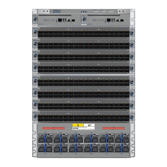
- Page 30 Figure 14: Front Panel (DCS-7808) 1 Power supplies 4 Linecards 7 Supervisor lock 2 Linecard and Supervisor 5 Linecard lock 8 Grounding locations extraction tool tether 3 Extraction tool 6 Supervisor modules 9 ESD attach point...
- Page 31 Cabling the Modular Switch Figure 15: Front Panel (DCS-7812) 1 Power supplies 4 Linecards 7 Supervisor lock 2 Linecard and Supervisor 5 Linecard lock 8 Grounding locations extraction tool tether 3 Extraction tool 6 Supervisor modules 9 ESD attach point...
-
Page 32: Cabling The Ac Power Supplies
Figure 16: Front Panel (DCS-7816) 1 Power supplies 6 Supervisor modules 11 Extraction tool 2 Linecard and Supervisor 7 Supervisor lock 12 Grounding locations extraction tool tether 3 Extraction tool 8 Linecards 13 ESD attach point 4 Linecards 9 Linecard lock 5 Linecard lock 10 Linecard and Supervisor extraction tool tether... -
Page 33: Cabling The Dc Power Supply
Cabling the Modular Switch Note: The power supply, handle color, orientation, etc. may be different in your device from the one shown in Figure 17: AC Power Supply. Figure 17: AC Power Supply Front Panel displays the front panel location of the power supplies. Note: •... -
Page 34: Wire And Lug Preparation
4.4.2 Wire and Lug Preparation Before performing any installation actions, ensure power is removed from DC circuits by turning off the power line servicing the circuits. Prepare the stranded wiring before you begin a DC power installation. 1. Stranded copper wiring is required. •... -
Page 35: Power Supply Configurations
Cabling the Modular Switch Table 8: Power Supply Specifications (each PSU) Power Supply Maximum Input Voltage Maximum Input Input Branch Output Power and Frequency Current Circuit Rating (DC) Protection PWR-D1-3041- 3000 W 200 to 240 2x 16 A 2x 20 A AC-BLUE VAC(nominal) 50/60 Hz... -
Page 36: Power Supply Redundancy
• All power supply slots must be filled with a powered supply, or a blank (X), or a non-powered power supply. • Valid redundancy configurations for each domain are described in Power Supply Redundancy section. Power Supply Redundancy Important: Installation of this equipment must comply with local and national electrical codes. If necessary, consult with the appropriate regulatory agencies and inspection authorities to ensure compliance. - Page 37 Cabling the Modular Switch supervisors. Refer to the chassis specification in Figure 21: DCS 7808 Supervisor Slots for additional information about the serial port. Figure 20: Supervisor DCS-7800-SUP, DCS-7800-SUP1A, and DCS-7816-SUP 1 Locking mechanism 5 Line card status LED 9 RJ-45 Serial management port 2 Supervisor status LED 6 Fabric Module status LED 10 USB Ports...
- Page 38 The appropriate supervisor cards must be installed in one of the two slots designated for them. They are shown in Figure 21: DCS 7808 Supervisor Slots for the DCS-7808 switch. For the DCS-7816 switch, the supervisor slots are in the middle of the chassis. Figure 21: DCS 7808 Supervisor Slots 1 Power supplies 4 Linecards...
-
Page 39: Connecting Line Card Modules And Cables
Flexion excessive peut endommager les câbles d'interface, en particulier les câbles optiques. Note: You must ensure that any open slots for modules, power supplies, etc. are covered by the appropriate “blank” plates. Check with your local Arista Networks representative if you have questions. -
Page 41: Chapter 5: Configuring The Modular Switch
Chapter 5 Configuring the Modular Switch Arista switches ship from the factory in Zero Touch Provisioning (ZTP) mode. ZTP configures the switch without user intervention by downloading a startup configuration file or a boot script from a location specified by a DHCP server. To manually configure a switch, ZTP is bypassed. The initial configuration provides one username (admin) accessible only through the console port because it has no password. - Page 42 11. When the management port IP address is configured, use this command to access the switch from a host, using the address configured in Step 9: ssh admin@192.0.2.8 Refer to the Arista Networks User Manual for the complete switch configuration information.
-
Page 43: Appendix A: Status Indicators
Appendix A Status Indicators The following topics are covered in this section: • Supervisor Module • Line Card Module Indicators • Fabric Module Status Indicators • Power Supply Status Indicators Supervisor Module While the front panel of each switch can house two supervisors, switch operations require only one. - Page 44 Supervisor Status LEDs Supervisor Status LED States interprets the states of the supervisor status LEDs for both the active and the redundant supervisor module. Table 10: Supervisor Status LED States Supervisor and System LED Name and State Condition Status Active Power Line Fabric...
-
Page 45: Line Card Module Indicators
Depends on port operation. Green for normal operation, red if no corresponding component is powered or present. Note: Arista modular switches take 15 to 30 minutes to boot completely. Line Card Module Indicators Each line card module provides one status LED plus LEDs for each port on the card. -
Page 46: Fabric Module Status Indicators
Linecard has failed. Red (blinking) Locator function is enabled. The line card provides LEDs for each port module socket: • Each LED corresponds to a module. • A set of four LEDs correspond to each module. When the module is programmed as a 40G port, the first LED in the set reports status. - Page 47 Status Indicators The following figure displays fan status and fabric status LEDs on the DCS-7812 switch. Figure 26: DCS-7812R3-FM Fabric Module 1 Fabric module top 6 Fan module 4 status LED 11 Fan module 8 status LED 2 Fabric module status LED 7 Fan module 5 status LED 12 Fan module 9 status LED 3 Fan module 1 status LED...
-
Page 48: Power Supply Status Indicators
Power Supply Status Indicators A.4.1 PWR-D1-3041-AC-BLUE The power supply status LEDs are on the power supply modules. Figure 28: PWR-D1-3041-AC-BLUE Power Supplies displays all the LEDs on the PWR-D1-3041-AC-BLUE AC power supply. Figure 28: PWR-D1-3041-AC-BLUE Power Supplies 1 Handle 4 AC_A LED 2 Output 5 Release 3 AC_B LED... -
Page 49: Pwr-D2-3041-Dc-Blue
Status Indicators PWR-D2-3041-DC-BLUE A.4.2 The power supply status LEDs are on the power supply modules. Figure 29: PWR-D2-3041-DC-BLUE Power Supplies displays all the LEDs on the PWR-D2-3041-DC-BLUE DC power supply. Figure 29: PWR-D2-3041-DC-BLUE Power Supplies 1 Status LED (Output) 4 Input_A LED 7 Battery return terminal 2 Release 5 Protective earth terminal... -
Page 51: Appendix B: Parts List
16x bolts Warning: All provided power cables are for use only with Arista products. Câbles d’alimentation doivent être utilisés uniquement avec des produits de Arista The following sections in the chapter list the installation parts provided by the accessory kit in more detail: •... -
Page 52: Parts Used In All Rack Mount Configurations
Parts Used in All Rack Mount Configurations Cables B.1.1 Table 17: Cables Provided in Accessory Kit Quantity Description RJ-45 Patch Panel Cables, 2 meters. RJ-45 to DB9 Adapter Cable, 2 meters. Getting-Started Booklet B.1.2 One 2-page document. Four-Post Rack Mount Parts The following sections list the parts provided in the accessory kit for four-post rack mount installations. - Page 53 Parts List Figure 30: Four-Post Rack Mount Parts Figure 31: Lifting Bracket and Bolts (DCS-7812 and DCS-7816 only) 1 Lifting bracket 2 Bolts...
-
Page 55: Appendix C: Front Panel
Appendix C Front Panel This appendix displays the front panel of all switches covered by this guide. Note: Depending on the components used to populate the chassis, the appearance of a specific switch could be different. Note: All switches are designed to fit in 19-inch racks. Figure 32: DCS-7804 Front Panel (Fully Populated) 1 Power supplies 4 Line cards... - Page 56 Figure 33: DCS-7808 Front Panel (Fully Populated) 1 Power supplies 4 Line cards 7 Supervisor lock 2 Line card and Supervisor 5 Line card lock 8 Grounding locations extraction tool tether 3 Extraction tool 6 Supervisor modules 9 ESD attach point...
- Page 57 Front Panel Figure 34: DCS-7812 Front Panel (Fully Populated) 1 Power supplies 4 Line cards 7 Supervisor lock 2 Line card and Supervisor 5 Line card lock 8 Grounding locations extraction tool tether 3 Extraction tool 6 Supervisor modules 9 ESD attach point...
- Page 58 Figure 35: DCS-7816 Front Panel (Fully Populated) 1 Power supplies 6 Supervisor modules 11 Extraction tool 2 Line card and Supervisor 7 Supervisor lock 12 Grounding locations extraction tool tether 3 Extraction tool 8 Line cards 13 ESD attach point 4 Line cards 9 Line card lock 5 Line card lock...
-
Page 59: Appendix D: Rear Panel
Appendix D Rear Panel This appendix displays the rear panel of all switches covered by this guide. Note: Depending on the components used to populate the chassis, the appearance of a specific switch could be different. Figure 36: DCS-7804 Rear Panel (Fully Populated) 1 ESD attachment point 3 Fabric modules 5 Fabric module ejector lever... - Page 60 Figure 37: DCS-7808 Rear Panel (Fully Populated) 1 Fabric module screw 3 Chassis ground 2 Fabric module ejector lever 4 ESD attachment point...
- Page 61 Rear Panel Figure 38: DCS-7812 Rear Panel (Fully Populated) 1 ESD attachment point 4 Fabric module ejector lever 2 Fabric module release button 5 Fabric module release button 3 Fabric module ejector lever...
- Page 62 Figure 39: DCS-7816 Rear Panel (Fully Populated) 1 Fabric module screw 5 ESD attachment point 9 Fabric module 2 Fabric module ejector lever 6 Fabric module screw 3 Fabric module screw 7 Fabric module ejector lever 4 Fabric module 8 Fabric module screw...
-
Page 63: Appendix E: Line Cards
Appendix E Line Cards This appendix displays the line cards supported by modular switches covered by this guide. Figure 40: DCS-7800R3-48CQ, DCS-7800R3K-48CQ, DCS-7800R3-48CQM, DCS-7800R3-48CQ2, DCS-7800R3-48CQMS, and DCS-7800R3-48CQM2 1 Line card status LED 3 Port status LEDs 2 Port numbers Figure 41: DCS-7800R3-36P 1 Line card status LED 3 Port status LEDs 2 Port numbers... - Page 64 1 Line card status LED 3 Port status LEDs 2 Port numbers...
-
Page 65: Appendix F: Maintenance And Field Replacement
Appendix F Maintenance and Field Replacement This appendix describes the process for replacing switch components. The following topics are covered in this section: • Line Card and Supervisor Extraction Tools • Power Supplies • Fabric and Fan Module (Fabric Module) •... -
Page 66: Assembling And Storing The Extraction Tools
F.1.1 Assembling and Storing the Extraction Tools The extraction tools come with a lanyard and tethering plug as shown in Figure 43: Linecard and Supervisor Module Extraction Tool and Tether Assembly. Figure 43: Linecard and Supervisor Module Extraction Tool and Tether Assembly Use the following steps to attach the tethering mechanism to the extraction tool. -
Page 67: F.2.2 Installing Ac Power Supply
Maintenance and Field Replacement F.2.2 Installing AC Power Supply You must make space for installing the power supply by removing an existing one (Removing AC Power Supply, Removing DC Power Supply) or removing a blank (Removing Power Supply Blank) from a power supply slot available on the switch. -
Page 68: Fabric And Fan Module (Fabric Module)
Note: You may want to save the blank for future use as needed. The blank is needed for the switch to operate normally if a power supply slot is not populated. Fabric and Fan Module (Fabric Module) The fabric and fan modules are hot-swappable. They are accessible from the rear of the switch (Rear Panel). -
Page 69: Installing Fabric Module
Maintenance and Field Replacement 4. Pull the ejector handles outwards by 90 degrees to disengage the fabric module. 5. Pull on the ejector handles to remove the fabric module from the slot. Note: Fabric modules can be heavier than 25 lbs. Provide adequate support while handling them to prevent injury or damage. - Page 70 1 Fabric module ejector levers 3 Fabric module seating claws 5 Fabric module seating claw 2 Claw position on chassis 4 Claw position on chassis 6 Claw position on chassis 5. Close the ejector levers in unison.
-
Page 71: Fan Module (Within Fabric Module)
Maintenance and Field Replacement CAUTION: Ensure that the claws engage correctly on the chassis. 1 Fabric module ejector levers 4 Claw position on chassis 7 Screw 2 Claw position on chassis 5 Fabric module ejector claw 8 Screw 3 Fabric module ejector claws 6 Claw position on chassis 6. -
Page 72: Supervisor Module
Note: See figure below. 1 Release latch 2 Fan lever 4. Lift the fan straight up and out of the fabric module. 5. Insert the replacement fan straight down and into the fabric module. 6. Rotate the fan lever to the closed position. 7. -
Page 73: Removing Supervisor Module Blank
Maintenance and Field Replacement 3. Slide supervisor module into slot. 4. Lock the supervisor module in place using the tool supplied (Front Panel). 5. Verify that the module is operating normally (Table 10: Supervisor Status LED States). F.5.3 Removing Supervisor Module Blank The supervisor module blank has plastic latches. -
Page 75: Appendix G: Regulatory Model Numbers
Appendix G Regulatory Model Numbers This appendix lists the Regulatory Model Numbers (RMNs), where applicable, for the product models for the switches described in this document. Table 19: Regulatory Model Numbers and Product Numbers Regulatory Model Number (RMN) Product Number(s) 7804 7804 7808... -
Page 77: Appendix H: Taiwan Rohs Information
Appendix H Taiwan RoHS Information This appendix provides Taiwan RoHS information for switches covered by this guide. For Taiwan BSMI RoHS Table, go to https://www.arista.com/assets/data/pdf/AristaBSMIRoHS.pdf.
Need help?
Do you have a question about the 7800 Series and is the answer not in the manual?
Questions and answers