Table of Contents
Advertisement
Quick Links
Advertisement
Table of Contents

Related Manuals for Upright X27RT


Summary of Contents for Upright X27RT
- Page 1 X27RT / X33RT X27BE / X33BE Operator Manual This first section of the Operator manual is the English language version. Diesel Bi-Energy 24V DC (EN) Manual part number 508401-003-EN for serial numbers 10131 to current. VERSION II June 08 ( Rev C )
- Page 3 Therefore any reference to the Snorkel SR Series also applies to the UpRight X-27-33-RT/BE . ENGLISH When contacting UpRight for service or parts information, be sure to include the MODEL and SERIAL NUMBERS from the equipment nameplate. Tanfield Engineering Systems Ltd.
- Page 5 NEVER charge bat ter ies near sparks or open flame. Charg ing bat ter ies emit ex plo sive hy dro gen gas. Mod i fi ca tions to the ae rial work plat form are pro hib ited or per mis si ble only at the ap proval by UpRight.
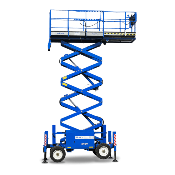
- Page 7 Standard X33RT / X27RT Version 2 and its com po nent parts as clearly as pos si ble. The stan dard X33RT / X27RT in cludes the fol - How ever, there may be mi nor dif fer ences be tween low ing fea tures: the pho to graphs and your ma chine.
- Page 8 It is the responsibility of the owner to ensure that who are not trained and authorised. Death or the person operating the X33RT / X27RT is serious injury can result from such provided with all the relevant information relating accidents.
- Page 9 Make an inspection of the work place to ● locate possible hazards before operating the ■ Additional information For ad di tional in for ma tion, con tact your lo cal dealer or UpRight at: UpRight Power Access HQ Vigo Centre, Birtley Road Washington Tyne &...
-
Page 10: Table Of Contents
Operation Manual......iii X27RT ......3-2 Photographs . -
Page 11: Options
Table of Contents Swinging Gate ......7-3 Pushing / Towing..... . . 9-2 Wiring Harnesses and Connectors . -
Page 12: Safety
The RT is not electrically insulated. Death or proper train ing, pro vide a ba sis for safely op er at ing the X33RT / X27RT. Know the lo ca tion of all the serious injury can result from contact with,... -
Page 13: Pre-Start Inspection
Do not op er ate an X33RT / X27RT that is dam - Any X33RT / X27RT op er ated in a haz ard ous lo - aged or not func tion ing prop erly. Do not use the RT... -
Page 14: Operation
General Safety Precautions Do not mod ify the X33RT / X27RT in any way. Do not op er ate the X33RT / X27RT from a po si - tion on trucks, trail ers, rail way cars, float ing ves -... -
Page 15: Fire Prevention
CAUTION There are sev eral safety de cals and plac ards on the X33RT / X27RT. Their lo ca tions and de scrip - DO NOT smoke or permit open flames while tions are shown in this sec tion. Take time to study fueling or near fueling operations. -
Page 16: Safety Placards And Decals Location
1. Safety Safety Placards and Decals Location LEFT HAND SIDE OF THE RT On Fuel Tank Inside Cabinet & Outside Of Cabinet Door TORQUE Lug Bolts/Nuts 90-100 Ft. Lbs.122-135 N m Check Every 30 Days 0372061 SR3370 & SR2770 – 13184A Rev A page 1 - 5... - Page 17 1. Safety RIGHT-HAND SIDE OF SR DANGER EMERGENCY OPERATION 1. EMERGENCY LOWERING SHEARING HAZARD/CRUSHING HAZARD Freewheel the Drive Motors In the event of total power failure pull the emergency lowering handle Death or serious injury might result from Turn the FREEWHEEL knob [A] Counterclockwise fully. mounted at the front of the chassis until the platform starts to descend.
- Page 18 1. Safety FRONT END OF RT DANGER DEATH OR SERIOUS INJURY CAN RESULT FROM TIPPING OVER. TO KEEP FROM TIPPING THIS MACHINE OVER FOLLOW THESE RULES. DO NOT RAISE OR DRIVE AN ELEVATED DO NOT RAISE OR DRIVE AN ELEVATED PLATFORM ON A PLATFORM ON BEWARE OF ELECTRICAL HAZARDS...
- Page 19 1. Safety REAR END OF RT X33RT X27RT PLATFORM RATINGS UNIFORMLY DISTRIBUTED RATED WORK LOAD RATED WORK LOAD EXTENSION MAIN MAIN DECK DECK DECK 450kg 330kg 120kg 264lb 990lb 726lb EXTENSION DECK RETRACTED EXTENSION DECK EXTENDED RATED NUMBER OF OCCUPANTS: 2 PERSONS...
-
Page 20: Safety Devices
2. Safety Devices Safety Device Information At ground control box For emer gency op er a tion con trols and pro ce dures see the Emer gency Op er a tion chap ter 9, in this manual. The de vices listed in this chap ter are safety de - vices. -
Page 21: Lowering
2. Safety Devices NOTE 2: The DRIVE (forward) and the platform-lowering alarms beep at one beep per second. DRIVE (re- The joystick must be released and then reapplied verse) beeps at two beeps per second. The level once the preset time period has elapsed before sensor alarm is a high-low warbling sound. -
Page 22: Safety Prop
2. Safety Devices ■ Safety Prop ■ Bubble Level Figure 2.8 - Bubble Level See the Gauges chapter 4 for a discussion of the level. Figure 2.5 - Safety Prop ■ Operator Horn Always raise the safety prop then lower the scis - sor-arm as sembly onto the safety prop be fore reaching into the scis sor-arm as sembly for any reason. -
Page 23: Rcd/Elcb Ac Outlet (Option)
2. Safety Devices NOTE The RT must be on a firm surface capable of w ithstanding all load forces imposed by the aerial platform in all operation conditions before the stabilisers are used. ■ RCD/ELCB AC Outlet (option) Power Outlet At Platform Power Input Connector... -
Page 24: Specifications
3. Specifications ■ Specifications The X33RT /X27RT se ries ma chines are scis sor-supported el evating work plat forms built to con form to the fol low ing stan dards. OSHA Paragraph 1910.67 Ti tle 29, C.F.R., Vehicle-Mounted El evating and Ro tating Work Plat forms - La- bour.OSHA Para graph 1926.556 Ti tle 29, C.F.R., Aerial Lifts - Con struction.Australian Stan dard... -
Page 25: General Specifications, Standard Machine
3. Specifications General Specifications, Standard Machine X27RT SPECIFICATIONS X27RT Nominal working height 10.28m 33' 9” Roll out deck size 1200mm 48” Drive speed (below 2.4m) 0 to 4.5kph 0 to 2.8mph Drive speed (above 2.4m) 0 to 0.9kph 0 to 0.6mph... -
Page 26: Engine Oil Charts
3. Specifications Engine Data Engine Make Kubota Model DF752 D902 Fuel gasoline Diesel Fuel grade Unleaded ASTM Grade 2-D S5000 85 octane Gas Processors Tier 4 Compliance: (motor method Association Low Sulpher Standard 2140 Do not use ASTM Grade 2-D S500 gasoline blended Category: special with methyl... -
Page 27: Machine Component Identification
3. Specifications Machine Component Identification 1. Base control panel 2. Serial number plate 3. Engine & fuel compartments 1. Extendable platform 2. Entry gate 3. Hydraulic compartment 4. Front end 5. Rear end 6. Guard rails 7. Steering (front) wheels 8. -
Page 28: Gauges
4. Gauges ■ Water The oil dipstick is the only way to ● accurately gauge if the engine oil level is correct. Engine oil level should always be between ● the lines on the dipstick - never above the top line or below the bottom line. Gas o line Die sel Figure 4.1 - Water Temperature Gauge... -
Page 29: Hours
4. Gauges ■ Hours ■ Bubble Level Figure 4.7 - Bubble Level A bub ble level is lo cated on the plat form side rail, Figure 4.5 - Hour Gauge below the plat form con trol box. Watch the bub ble The HOURS gauge is ba sically an elec tric clock. -
Page 30: Automatic Shut-Offs And Circuit Breakers
5. Automatic Shut-offs and Circuit Breakers Automatic Shut-offs engine shuts off. The engine will restart with low pressure but it will only run a few seconds before it automatically shuts off again. Level sensor When the level sen sor alarm sounds, au to matic in - Platform height vs. -
Page 31: Circuit Breakers
5. Automatic Shut-offs and Circuit Breakers Load sensing system RCD / ELCB outlet (option) The load sens ing sys tem sounds an alarm to warn the op er a tor that the plat form is over loaded. NOTE: When the alarm sounds all plat form move ment [drive for ward / re verse and lift up / down is pre - vented]. -
Page 32: Controls
6. Controls Controls Hydraulic Compartment This chap ter ex plains what each con trol does. This chap ter does not ex plain how to use the con - trols to pro duce use ful work, re fer to the Op er a tion chap ter 8 for that, af ter you have read this chapter. -
Page 33: Platform Control Box
6. Controls 1. Emergency Stop: Press the red switch-cover down, at any time, under any conditions, and the entire machine stops - the engine turns off and nothing moves. This switch must be up for anything on the machine to work. 2. - Page 34 6. Controls 7. Steering: The rocker switch on top of the NOTE JOYSTICK CONTROLLER turns the front wheels left or right depending upon which The EMERGENCY STOP switch on the ground side of the switch you press. control box overrides the one on the platform control box.
-
Page 36: Daily Inspection And Maintenance
7. Daily Inspection and Maintenance At the start of each work day (or 8 hour shift), an RT De fec tive parts and/or equip ment mal func tions qual i fied op er a tor must per form the Daily In spec - jeop ar dize the safety of the op er a tor and other per - tion and main te nance (or Pre-Op er a tion In spec tion son nel, and can cause dam age to the ma chine. -
Page 37: Fuel Level
7. Daily Inspection and Maintenance The rest of this chap ter shows how to per form the Fuel Filter (diesel engines only) in spec tion and main te nance re quired for each item in the daily in spec tion and main te nance table. Fuel Level Figure 7.3 - Fuel Filter The D902 has, in ad di tion to the fil ter (B), a pre-fil ter... -
Page 38: Engine Oil
7. Daily Inspection and Maintenance Engine Oil Radiator Cap Figure 7.8 - Radiator Cap Vi su ally check to see that the cap is in place and Figure 7.6 - Engine Oil Level tight. Keep the oil level be tween the marks on the dip - stick (see Fig ure 7.6). -
Page 39: Battery Terminals
7. Daily Inspection and Maintenance Remove the caps from the battery and visually check to see that the battery fluid is 1/4 (6 mm) below the bottom of the filler neck inside each hole Hydraulic Oil Tank Figure 7.11 - Wiring Harness in the Scissor Stack Pay par tic u lar at ten tion to the wir ing har nesses Figure 7.13 - Hydraulic Oil Tank... -
Page 40: Tires And Wheels
7. Daily Inspection and Maintenance Check all fit tings and hoses for leaks. In spect hoses for signs of dam age from chaff ing or rub bing against pro tru sions on the chas sis or scis sor stack. Figure 7.17 - Critical Pin Retainer Bolts Crit i cal pin re tainer bolts have lock tab wash ers fit - ted, they should all be pres ent and not dam aged in any way. -
Page 41: Structural Damage & Welds
7. Daily Inspection and Maintenance Structural Damage & Welds Bubble Level Figure 7.22 - Bubble Level Vi su ally check to see that the bub ble level is not Figure 7.19 - Structural Damage and Welds dam aged, that it is full of fluid, that the bub ble does not ex ceed the di am e ter of the cen ter black cir cle, and the sur face on which the bub ble level is mounted is not de formed or bent out of level. -
Page 42: Charging System
7. Daily Inspection and Maintenance Charging System Flashing Light Figure 7.27 - Flashing Light Figure 7.24 - Ammeter Gauge Check to see that the light flashes ap prox i mately once a sec ond when the RT en gine is run ning. With the en gine idling, the nee dle in the AMPS gauge should not be to the left of 0"... -
Page 43: Emergency Lowering
7. Daily Inspection and Maintenance Emergency Lowering Safety prop Figure 7.29 - Emergency Lowering To check the emer gency low er ing: Raise the plat - form and turn the en gine OFF at the ground con trol box KEY SWITCH. Figure 7.31 - Safety Prop Op er ate the emer gency lower by pull ing on the ca - In spect the safety prop(s) to see that it is pres ent... -
Page 44: Wrist Support
7. Daily Inspection and Maintenance Wrist Support Figure 7.33 - Wrist Support Check the con di tion of the rub ber on the up per con - trol box wrist sup port. Re place it if it is worn or dam - aged. -
Page 45: Placards And Decals
Decal - Torque wheel nuts 0372061 Decal - X27RT 11345-1 Decal - www.snorkellift.com 13182 Decal - Rated load, X33RT 12699 Decal - Rated load, X27RT 11346-1 Decal - Foam tyres 0073298 Decal - Interlocks 451986 Decal - Explosive fumes 476706... -
Page 46: Inspection Drawing
7. Daily Inspection and Maintenance Inspection drawing RIGHT HAND SIDE LEFT HAND SIDE REAR END FRONT END SR3370 & SR2770 – 13184A Rev A page 7 - 11... -
Page 48: Operating Procedures
8. Operation Operating Procedures Emergency Stopping This chap ter ex plains how to start and run an RT To stop an RT, push ei ther Emer gency Stop that has ei ther a gas o line or die sel en gine. Start ing switch, at any time on ei ther the ground con trol box a gas o line en gine that is set up to burn LP-only or or the plat form con trol box and the en tire ma chine... -
Page 49: Fuel Type
8. Operation Fuel type Af ter you have made the ground con trol / plat form con trol de ci sion you need to know whether the RT has a gas o line or die sel en gine. If it has a gas o line en gine you fur ther need to know whether it is set up to burn LP-only, or dual-fuel (LP or gas o line). -
Page 50: Raising The Platform
8. Operation 4. For LP operation: 1. Set the Battery switch to on (see Figure Completely open the valve (see Figure 8.7). 8.5) on top of the LP tank (unscrew counterclockwise until it stops). Figure 8.8 2. Set the Emergency Stop switch to on Figure 8.6 (up) (see Figure 8.8). -
Page 51: Operating From The Platform Control Box
8. Operation 1. Set the Battery switch to on (see Figure 8.10). Figure 8.9 2. To raise the platform, press and hold the Platform Lift/Lower switch up (see Figure Figure 8.11 8.9). 2. Set the Emergency Stop switch to on (up) (see Figure 8.11). - Page 52 8. Operation Starting a diesel engine To start a die sel en gine from the plat form con trol box do the fol low ing: Figure 8.13 Figure 8.15 5. For a dual-fuel engine: 1. Set the Battery switch Set the FUEL switch to gasoline or LP to on (see Figure...
-
Page 53: Driving
8. Operation Driving 1. The engine should be running. If not, start it from the platform control box as described previously. Figure 8.17 6. Turn the Emergency Stop switch clockwise and it will pop out (on) (see Figure 8.17). Figure 8.18 7. -
Page 54: Raising The Platform
8. Operation 3. Squeeze and hold the Safety Control NOTE against the Joystick Controller (see Figure 8.19). When you release the Steering rocker-switch the steering wheels remain pointed in the 4. Pull the Joystick Controller backward to direction you left them. They do not return to raise the platform, or push it forward to lower straight ahead the way automobile wheels do. -
Page 55: Operating The Stabilisers Manually
8. Operation sta bi lis ers is even slightly low ered the DRIVE 3. Visually check the bubble level func tion is dis abled. determine which stabilisers must be further extended to level the platform (see Figure 8.22). Operating The Stabilisers Manually NOTE To set the stabilisers When the bubble... -
Page 56: Operating The Auto Level System
8. Operation Operating The Auto Level System Extending The Multi-Position Platform DECK EXTENSION Setting the stabilisers automatically HANDLE LOCKED 1. The engine must be running and the RT set for platform control box operation. DECK EXTENSION HANDLE UNLOCKED NON-EXTENDABLE EXTENDABLE PLATFORM PLATFORM Figure 8.26... -
Page 58: Emergency Operation
9. Emergency Operation Emergency Operation Procedures To re set the Emer gency Stop switch at the plat - form con trol box, pull it and and it will pop out (on). The fol low ing pro ce dures are emer gency pro ce - To re set the Emer gency Stop switch at the ground dures only. -
Page 59: Pushing / Towing
9. Emergency Operation 1. Check to be sure the Battery switch 6. If the platform will not lower, the person on the ground will need to use the manual bleed ON. (See Figure 9.4) down (see Figure 9.6) located at the front of the chassis.To lower the platform pull on the cable ) until the platform is fully... - Page 60 9. Emergency Operation Figure 9.9 Figure 10.11 3. Inside the hydraulic compartment, open the 5. Once the unit has been safely pushed / free-wheeling valve by turning towed pull the re-set knob to re-apply the counterclockwise until knob stops.(see brakes (see Figure 9.11) and close the Figure 9.9).
-
Page 62: Stowing And Transporting
10. Stowing and Transporting To lock an RT: Stowing At the end of each work day (or in prep a ra tion for trans port ing, push ing, lift ing, or stor age) a qual i fied op er a tor should put the RT into its stowed po si tion then lock it. -
Page 63: Transporting
10. Stowing and Transporting 3. (Option - LPG) For machines equipped with LPG: Close the valve (see Figure 10.4)on the LPG-tank (completely screwed in). Transporting Trailering DANGER S R s w e i g h up t o 3 6 2 0 k g ( 7 9 6 4 l b s ) depending on the model. -
Page 64: Towing
10. Stowing and Transporting Figure 10.6 2. Set the Battery switch (see Figure 10.6) to OFF and padlock it. Figure 10.9 - Tie-down Lugs Chocks may be re moved at this time, though it is a good idea to leave them in place. Re verse the above pro ce dure af ter trans port ing. - Page 65 10. Stowing and Transporting 8. Reset the hydraulic system by reversing these procedures. page 10 - 4 Rev A SR3370 & SR2770 – 13184A...
-
Page 66: Bi-En Ergy Option
11. Options This chap ter lists and ex plains the op tions avail - Af ter se lect ing the DC mode, turn the ig ni tion able for an RT. switch to the ON po si tion (the sec ond po si tion of the switch) at the ground con trol box (see Fig ure 11.3) Bi-En ergy Option... -
Page 67: Steering In Dc Motor Mode
11. Options Figure 11.7 - DC Motor Batteries Figure 11.5 - Master Battery Isolator Switches IMPORTANT Steering in DC motor mode The cab i net lid must be open whilst charg ing Be cause of the con fig u ra tion of the con trol mech a - to al low gas ses to es cape. -
Page 68: Batteries - General Maintenance
11. Options The battery charger is fitted with an 'interlock". This Batteries - Charging means that during the charging cycle all functions Fully re charge the bat ter ies, im me di ately af ter use. on the machine are inoperative and will remain so One charg ing cy cle per day is pre ferred. -
Page 69: Lanyard Anchor Points
11. Options Lanyard Anchor Points There are four an chors on the floor of the plat form, one at the front of the roll-out deck, one at the back of the plat form, and one on each side of the plat - form. -
Page 70: Fire Fighting And Chemical Containment
12. Fire Fighting and Chemical Containment Hazardous Components Special fire fighting procedures: The RT may con tain some or all the fol low ing ma te - Use pos i tive pres sure, self con tained breath ing ap - ri als and ob jects that po ten tially could be come sig - pa ra tus. - Page 71 12. Fire Fighting and Chemical Containment Special fire fighting procedures: DANGER Use wa ter to keep fire ex posed con tain ers cool. If Burning produces intense heat, dense leak or spill has not ig nited, use wa ter spray to dis - smoke, and toxic gases, such as carbon perse the va pors and to pro vide pro tec tion for per - monoxide, oxides of nitrogen, and traces of...
-
Page 72: Hydraulic Oil (Un 1270)
12. Fire Fighting and Chemical Containment c o m p l y i n g w i t h f e d e r a l , s t a t e , a n d l o c a l NOTE regulations. - Page 73 12. Fire Fighting and Chemical Containment Special fire fighting procedures: Wa ter or foam may cause froth ing. Use wa ter to keep fire ex posed con tain ers cool. Wa ter spray may be used to flush spills away from ex po sures. Unusual fire and explosion hazards: Prod ucts of com bus tion may con tain car bon mon - ox ide, car bon di ox ide, and other toxic ma te ri als.
-
Page 74: Operator's Troubleshooting
13. Operator's Troubleshooting Troubleshooting CAUTION All of the ac tions de scribed in this chap ter may be per formed by an RT op er a tor, a trained and qual i - Any problem that cannot be fixed by actions listed below should be referred to a trained fied ser vice tech ni cian is not required. - Page 75 13. Operator's Troubleshooting Problem Cause Remedy Platform will not go up Engine is not running. Start the engine from the control station where you will operate the RT. or down. Switches set wrong For ground control operation: (Lift Indicator light is lit). Ground/Platform Selector = Ground For platform control box operation: Ground/Platform Selector = Platform...
-
Page 76: Appendix A. Glossary
Appendix A. Glossary ae rial plat form ground fault cir cuit in ter rupter or re sid ual cur rent de tec tor a mo bile de vice that has an ad just able po si tion plat form, sup ported from ground level by a a fast-act ing cir cuit breaker that opens to stop struc ture. - Page 77 op er a tor upper controls a qual i fied per son who con trols the move ment of the controls located on or beside the platform an ae rial plat form. used for operating some or all of the functions of the aerial platform.
- Page 78 Hydraulic Oil, 4-1 Joystick safety control, 6-3 LPG Fuel Level, 4-2 Key switch, 6-2 Water, 4-1 Lift/drive, 6-3 General Specifications X27RT, 3-2 Manual stabiliser, 6-3 General Specifications X33RT, 3-1 Operator horn, 6-3 Gradeability, 3-1, 3-2 Platform lift/lower, 6-2 Ground clearance, 3-1, 3-2...
- Page 79 Index Safety Maintenance personnel Batteries, 1-4 see Introduction - page iv Electrocution Hazard, 1-1 Maximum rated axle capacity, 3-1, 3-2 Falling Hazard, 1-3 Minimum Safe Approach Distance Fuel Handling Precautions, 1-3 see Electrical Hazard - page ii General Safety Precautions, 1-3 Hydraulic Systems, 1-3 Pre-start Inspection, 1-1 Nominal working height, 3-1, 3-2...
- Page 80 Index Troubleshooting, 13-1, 13-2 All systems sluggish, 13-1 Engine will not start, 13-1 Operator Troubleshooting Chart, 13-1 Platform will not drive when raised, 13-2 Platform will not go up, 13-2 RT will not drive, 13-1 Turning radius (inner), 3-1, 3-2 Turning radius (outer), 3-1, 3-2 Warranty - Limited see inside front cover...
- Page 82 Local Distributor: Lokaler Vertiebshändler: Distributeur local: El Distribuidor local: Il Distributore locale: Plaatselijke dealer: Europa TEL: +1 (559) 443 6600 TEL: +44 (0) 845 1550 058 FAX: +1 (559) 268 2433 FAX: +44 (0) 195 2299 948 www.upright.com PN - 508401-003...
Need help?
Do you have a question about the X27RT and is the answer not in the manual?
Questions and answers