Promax HD Ranger+ User Manual
Tv & satellite analyser
Hide thumbs
Also See for HD Ranger+:
- User manual (224 pages) ,
- User manual (266 pages) ,
- Manual (182 pages)
Table of Contents
Advertisement
Quick Links
Advertisement
Table of Contents

Related Manuals for Promax HD Ranger+


Summary of Contents for Promax HD Ranger+
- Page 1 RANGER/ TV & SATELLITE ANALYSER - 0 MI1914 -...
-
Page 3: Safety Notes
SAFETY NOTES Read the user’s manual before using the equipment, mainly " SAFETY RULES " paragraph. The symbol on the equipment means "SEE USER’S MANUAL". In this manual may also appear as a Caution or Warning symbol. WARNING AND CAUTION statements may appear in this manual to avoid injury hazard or damage to this product or other property. - Page 5 SAFETY RULES The safety could not be assured if the instructions for use are not closely followed. Use this equipment connected only to systems with their negative of measurement connected to ground potential. The AL-103 external DC charger is a Class I equipment, for safety reasons plug it to a supply line with the corresponding ground terminal.
-
Page 6: Descriptive Examples Of Over-Voltage Categories
Symbols related with safety: Descriptive Examples of Over-Voltage Categories Cat I Low voltage installations isolated from the mains. Cat II Portable domestic installations. Cat III Fixed domestic installations. Cat IV Industrial installations. -
Page 7: Table Of Contents
T A B L E C O N T E N T S SAFETY RULES ....................1 Descriptive Examples of Over-Voltage Categories ........... 2 1 INTRODUCTION ..................1-1 1.1 Description..................1-1 2 SETTING UP ....................2-3 2.1 Package Content ................2-3 2.2 Power .................... - Page 8 6 TOOLS ....................6-42 6.1 Constellation .................. 6-42 6.1.1 Description .................. 6-42 6.1.2 Operation ..................6-42 6.1.3 Menu Options ................6-44 6.2 LTE Ingress test................6-44 6.2.1 Description .................. 6-44 6.2.2 Operation ..................6-45 6.2.3 Options Menu ................6-46 6.3 Echoes ..................6-47 6.3.1 Description ..................
-
Page 9: Introduction
RANGER/ 1 INTRODUCTION Description The new is the fifth generation of field meters that PROMAX RANGER/ launches. As each new generation, it represents an evolution from the previous, since it integrates the latest technological innovations and develops applications for the new demands and needs that have emerged in recent years. - Page 10 Besides the basic functions of TV meter and spectrum analyser for terrestrial and satellite band, it provides additional tools, such as the detection of 4G signal interferences (some of its working frequencies are close to the TV bands), the diagrams constellations or the echoes detection.. has an application to manage data generated at each RANGER/ installation.This feature helps the user to manage information generated so he...
-
Page 11: Setting Up
2 SETTING UP Package Content Check that your package contains the following elements: Field Meter. RANGER/ External DC charger. Mains cord for external DC charger. Car lighter charger. "F" Adapters (3 units). • "F" / H - BNC / H Adapter. •... -
Page 12: Power
Power is powered by a 7.2 V built-in rechargeable Li-Ion battery RANGER/ of high quality and long duration. The equipment can operate on battery or connected to the network using a DC adapter. An adapter is also supplied to use with the power connector car (cigarette lighter). -
Page 13: Charge / Discharge Times
When the computer is connected to the mains, the CHARGER indicator remains on. This indicator changes its colour according to the percentage of battery charge: Less than 80% of charge. ORANGE Between 80% and 90% of charge. GREEN 100% full charge. If the battery is weak, the battery disconnection circuit will prevent the equipment starting up. -
Page 14: Usage Tips
Usage Tips The battery is losing storage capacity as you go through its life. Contact your PROMAX distributor when necessary to replace the battery. To prolong battery life the user should follow these tips: Proceed to charge the battery preferentially when fully discharged. -
Page 15: Equipment Details
Equipment Details Front View Figure 4. August 2012... - Page 16 Lateral view Figure 5. Top view Figure 6. * Optical Option. August 2012...
-
Page 17: Switching On / Off The Equipment
Switching On / Off the equipment This field meter is designed for use as a portable equipment and it does not require any previous installation. Switching On: ► Slide up for a while the power slide switch located on the left side of the equipment (approximately one second). -
Page 18: Screen Icons And Dialog Boxes
Screen Icons and Dialog boxes At the top of the screen there is the status bar. On the right are icons that provide useful information to the user about the current status of the instrument. Battery charging. USB flash drive inserted Battery not charging. -
Page 19: Menu Tree
Menu Tree SPECTRUM ANALYSER MENU TV MENU August 2012 2-11... - Page 20 MEASUREMENT MENU SETTINGS MENU 2-12 August 2012...
- Page 21 INSTALLATIONS MANAGEMENT / PREFERENCES MENU Figure 7. August 2012 2-13...
-
Page 22: Controls
Controls The equipment has been designed to be an easy tool to use. For this reason the number of keys has been reduced and these are grouped by function. For measurement and navigation through the menus, the equipment has a joystick, 4 programmable keys (softkeys) and 6 direct access keys. -
Page 23: Keyboard Shortcuts
2.7.2 Keyboard shortcuts Function keys ► On the left side of the device are 3 keys to access the most important functions of the equipment. Measurement key. Spectrum analyser key. TV Mode Key. Pressing the key provides access to a different view within the same function. Each view is shown at the top. - Page 24 Measurements Figure 10.- FULL MEASUREMENT Figure 11.- MEASUREMENT + TV + SPECTRUM Figure 12.- MEASUREMENT + PARAMETERS 2-16 August 2012...
- Page 25 Spectrum Analyser Figure 13.- SPECTRUM + MEASUREMENT Figure 14.- SPECTRUM + MEASUREMENT + TV Figure 15.- FULL SPECTRUM August 2012 2-17...
- Page 26 Modo TV Figure 16.- FULL TV Figure 17.- TV + SPECTRUM + MEASUREMENT Figure 18.- TV + SERVICE DATA 2-18 August 2012...
-
Page 27: Softkeys
Screenshot key This key captures the screen currently being displayed and stores it in the memory of the equipment in PNG format. This screen can be displayed on the same instrument and if desired, downloaded to a computer. Management Keys ►... -
Page 28: Measurement Mode
3 MEASUREMENT MODE Introduction At the left side, the equipment have three functions keys, which give direct access to the three most important functions. One of them is the key MEASURES ( ) that measures the signal received through the RF input connector. -
Page 29: Operation
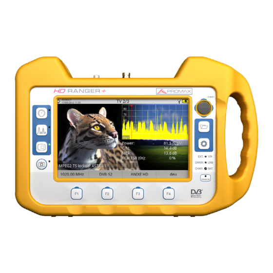
Operation Connect the RF input signal to the equipment. Select through the Tune Settings menu the frequency band (terrestrial or satellite). Access the MEASURES option by pressing the key. Press again to display the next view. Views for the digital signal are: MEASUREMENT 1/3: FULL MEASUREMENT Figure 20. - Page 30 MEASUREMENT 2/3: MEASUREMENT + TV + SPECTRUM Figure 21. Selected installation, date and time. Image of the locked signal. Number of view / total views. Selected band, battery level. Spectrum of the locked signal. Measurement values for the type of locked signal. Signal status (searching / locked / multiplex name).
- Page 31 MEASUREMENT 3/3: MEASUREMENT + PARAMETERS Figure 22. Selected installation, date and time. Number of view / total views. Selected band, battery level. Demodulation parameters of the locked signal. Measurement values for the type of locked signal. Signal status (searching / locked / multiplex name). Softkeys menus.
-
Page 32: Spectrum Analyser Mode
4 SPECTRUM ANALYSER MODE Introduction At the left side, the equipment has three function keys, which give direct access to the three most important functions. One of them is the SPECTRUM ANALYSER key that displays the signal spectrum received through the RF input connector. - Page 33 Views for the digital signal are: SPECTRUM 1/3: SPECTRUM + MEASUREMENTS Figure 23. Selected installation, date and time. Number of view / total views. Selected band, battery level. Measured values of the signal at the frequency / channel where is pointing the cursor.
- Page 34 SPECTRUM 2/3: SPECTRUM + MEASUREMENT + TV Figure 24. Selected installation, date and time. Number of view / total views. Selected band, battery level. Measured values of the signal at the frequency / channel where is pointing the cursor. Image of the tuned signal. Spectrum in the band with the selected SPAN.
- Page 35 SPECTRUM 3/3: FULL SPECTRUM Figure 25. Selected installation, date and time. Number of view / total views. Selected band, battery level. Spectrum in the band with the selected SPAN. Softkeys menus. August 2012 4-27...
-
Page 36: Description Of The Full Spectrum Screen
Description of the FULL SPECTRUM screen. Figure 26. Horizontal reference line It indicates the signal level. Vertical axis It indicates the signal level. Vertical reference line It indicates the frequency. SPAN It is the frequency range displayed on the horizontal axis. The current SPAN value appears at the bottom right of the screen. -
Page 37: Joystick Operation In Spectrum Analyser Mode
Cursor Red vertical line that indicates position during the channel or frequency tuning. To change use the joystick (left, right) in FR mode (tuning by frequency) or CH mode (tuning by channel). Marker It is a special cursor that can be placed on a given frequency to check the power in this point. -
Page 38: Options Menu
Pressing up or down will change the reference level regardless the active mode. The frequency or channel tuning mode will appear depending on the selected tuning type. Access the ADJUST menu to select the type of tuning. To show the MARKER mode, it must be active. Access the ADVANCED menu (F4) to activate the MARKER. -
Page 39: F1: Tuning
4.5.1 F1: Tuning Access by the function key , it contains the options to tune a channel. The tuning menu consists of the following options: Channel / Frequency: It displays the channel / frequency pointed by the ► cursor. In channel tuning, it allows selecting a channel from the active channel plan: Place over the Channel option and press the JOYSTICK. - Page 40 Central Frequency: It displays the value of the central frequency on the ► screen. To edit: Place over the Frequency option and press the JOYSTICK. The option is highlighted in yellow to indicate it is in edit mode. Move the JOYSTICK left / right to move between the figures and up / down to change the figure.
-
Page 41: F2: Signal Parameters
4.5.2 F2: Signal Parameters Access by the function key, it allows selecting the standard transmission and displays the parameters for signal transmission. This menu allows selecting the transmission standard: Type of signal: It displays the selected standard. It allows selecting another ►... -
Page 42: F4: Advanced
4.5.4 F4: Advanced Access by the function key, it allows selecting among several parameters to display the spectrum. The advanced menu consists of the following options: Average: The user can select the amount of signal values to be used to ►... -
Page 43: Location Of A Signal With The Spectrum Analyzer
Location of a signal with the SPECTRUM ANALYZER Connect the cable with the input signal to the RF IN input connector. Press the SPECTRUM key. The spectrum of the signal is displayed. Adjust the SPAN (recommended value for a terrestrial signal 50 MHz and for a satellite signal 100 MHz). -
Page 44: Tv Mode
5 TV MODE Introduction On the left side of the front panel there are three functions, which give direct access to the three most important functions. One is the TV MODE key which displays the resulting image from the decoding the received RF signal. TV MODE demodulates the TV signal received by the RF input, so that the user can check the signal on the screen. - Page 45 Views for the digital signal are: TV 1/3: FULL TV Figure 29. Selected installation, date and time. Number of view / total views. Selected band, battery level. Tuned service image. Signal status (searching / locked / multiplex name). Softkeys menus. Joystick up / down: It changes service.
- Page 46 TV 2/3: TV + SPECTRUM + MEASUREMENT Figure 30. Selected installation, date and time. Number of view / total views. Selected band, battery level. Tuned service image. Spectrum. Measured values of the signal in the frequency / channel the cursor is pointing.
- Page 47 TV 3/3: SCREEN TV + SERVICE DATA Figure 31. Selected installation, date and time. Tuned service image. Tuned service information. TYPE: Encoding type and video transmission rate. ► FORMAT: Resolution (horizontal x vertical) aspect ratio and ► frequency. PROFILE: Profile level. ►...
-
Page 48: Menu Options
Tuned audio information. TYPE: Type of audio encoding and transmission speed ► FORMAT: ► LANGUAGE: Broadcasting language. ► PID: ID of the audio program. ► Softkeys menus. Joystick up / down: It changes service. ► Joystick left / right: It changes channel / frequency. ►... -
Page 49: F3: Selected Service Name
5.3.2.3 F3: Selected service name. It displays the list of services available in the multiplex tuned, with information about the service type and the identification number. Icons that appear next to the service name identify the features of the service. The meaning is given in the following table: Digital TV High Definition... -
Page 50: Tools
6 TOOLS Constellation 6.1.1 Description The constellation diagram is a graphic representation of the digital symbols received over a period of time. There are different types of constellation diagrams according to the modulation type. In the case of an ideal transmission channel without noise or interference, all symbols are recognized by the demodulator without errors. - Page 51 The following describes the constellation screen: Figure 32. Selected installation, date and time. Constellation window. The colour scale placed at the left side indicates the signal quality in a qualitative way by a gradation of colours proportional to the density of symbols concentrated in a given area.
-
Page 52: Menu Options
6.1.3 Menu Options At the bottom of the screen there are four menus accessible via the function keys. It displays the channel / frequency where is pointing the cursor and access the tuning menu. It displays the selected transmission standard menu and accesses the signal parameters. -
Page 53: Operation
6.2.2 Operation The LTE Ingress Test input is available to all DIGITAL TERRESTRIAL signals. To access the LTE Ingress Test tool: Connect the RF input signal to the equipment. Tune a digital signal of the terrestrial band. Enter the MEASUREMENT mode or SPECTRUM mode Press the F3 key (Utilities). -
Page 54: Options Menu
Signal with LTE filter ON. Identifier icon of the LTE filter ON. Selected band, battery level. Elapsed Time with filter OFF. Measurement with filter OFF: MER (minimum, maximum) and power (minimum, maximum). Signal with LTE filter OFF. Measurement units / centre frequency / Span. Signal status (searching / locked / multiplex name). -
Page 55: Echoes
Echoes 6.3.1 Description The Echoes option shows the response in time of a digital terrestrial channel and therefore it can detect echoes that can occur due to the simultaneous reception of the same signal from several transmitters with different delays and amplitudes. - Page 56 The following describes the ECHOES screen: Figure 34. Selected installation, date and time. Selected band, battery level. Main signal data: Frequency, Power and C / N. ECHOES Diagram. The display shows a graphical representation of the echoes. The horizontal axis of the graph corresponds to the delay in receiving the echo on the main path (the stronger signal).The vertical axis represents the attenuation of the echo in dB on the main path.
-
Page 57: Menu Options
6.3.3 Menu Options At the bottom of the screen there are four menus available via the function keys. It displays the channel / frequency where is pointing the cursor and access the tuning menu. It displays the selected transmission standard menu and accesses the signal parameters. -
Page 58: Installation Manager
Installation Manager When accessing the INSTALLATION MANAGER the following screen appears: Figure 35. The window is divided into three fields: Installation data It displays information about the installation using the following fields: Name: ► Name of the installation file. Created: ►... - Page 59 List of channel sets and screenshots It shows all channel sets and / or screenshots available for the selected installation. Display area It is the area where the selected file is displayed, both channel set and screenshots. In the case of displaying a channel set file, it shows the name, the band and the number of channels of the channel set on which the cursor is placed.
- Page 60 INSTALLATION Edit name: ► It edits the name of the currently selected installation. Delete: ► It deletes the name of the currently selected installation. Duplicates: ► It allows double the currently selected installation. CURRENT INSTALLATION The function key displays the name of the current installation. Pressing the key, a menu displays installations available so the user can switch installation.
-
Page 61: Specifications
7 SPECIFICATIONS Specifications RANGER CONFIGURATION FOR MEASURING LEVEL AND POWER TUNING Digital frequency synthesis. Continuous tuning from 5 to 1000 MHz MEASURE and from 950 to 2150 MHz. (Terrestrial and Satellite respectively). Tuning Digital frequency synthesis. Demodulator Terrestrial TV 45 - 860 MHz. &... - Page 62 DVB-S2 Power, CBER, LBER, MER (up to 30 dB), C/N, BCH ESR, Wrong Packets (QPSK/8PSK): and Link Margin. Presentación: Numeric and level bar. DVB-T SIGNAL PARAMETERS Carriers 2k / 8k. Guard Interval 1/4, 1/8, 1/16, 1/32. Code Rate 1/2, 2/3, 3/4, 5/6, 7/8. Modulation QPSK, 16-QAM, 64-QAM.
- Page 63 DVB-C2 SIGNAL PARAMETERS Carriers Guard Interval 1/64, 1/128. Bandwidth 6 and 8 MHz. Spectral ON, OFF (AUTO). Inversion Code Rate PLP 2/3, 3/4, 4/5, 5/6, 8/9, 9/10. 64QAM, 256QAM, 1kQAM and 4kQAM. Constellation Dslice ID 0-256. PLP ID 0-256. ID cell Detected from transmitter station.
- Page 64 ECHOES ANALYSER MODE (DVB-T / DVB-T2 / DVB-C2) Measurement Depends on the standard, carrier and guard interval. range Delay 0.1 ms to 224 ms. Typical configuration (DVB-T 8K, GI = 1/4) Distance 0.3 km to 67.2 km. Typical configuration (DVB-T 8K, GI = 1/4) Power range 0 dBc to –30 dBc.
- Page 65 Attenuation Auto-range. scale Numerical Absolute value according to selected units. indication Graphical Analogue bar on screen. indication Measurement 100 kHz. bandwidth Audible Pitch sound. A tone with pitch proportional to signal strength. indicator Accuracy Terrestrial ±1,5 dB (25-120 dBµV, 45-1000 MHz) (22 °C ± 5 °C). bands Satellite band ±1,5 dB (35-100 dBµV, 950-2050 MHz) (22 °C ±...
- Page 66 Measurements Terrestrial bands Analogue Level, C/N, V/A. channels Digital Channel power, C/N, MER and BER (according to modulation channels type). Satellite band Analogue Level, C/N. channels Digital Channel power, C/N, MER and BER (according to modulation channels type). Spectrum Span, dynamic range and reference level are variable by means range of arrow cursors.
- Page 67 > 5 hours in continuous mode (no EXT supply active). Recharging 3 hours up to 80% (instrument off). time External 12 V DC (using only PROMAX supplied accessories). Voltage Consumption 35 W. Auto power off Programmable. After the selected amount of minutes without operating on any control.
- Page 68 INCLUDED ACCESSORIES. 1x CC-046 CABLE JACK 4V/RCA. 1x CC-041 Connection USB Cable On-the-go (A) Male – Mini USB (B) Male. 1x CC-045 USB Cable (A) Female – Mini USB (A) Male. 1x AA-103 Car lighter charger. 1x AL-103 External DC charger. 1x AD-055 "F"/H-BNC / H adapter.
- Page 69 Specifications RANGER CONFIGURATION FOR MEASURING LEVEL AND POWER TUNING Digital frequency synthesis. Continuous tuning from MEASURE 1000 MHz and from 950 to 2150 MHz. (Terrestrial and Satellite respectively). Tuning Digital frequency synthesis. Demodulator Terrestrial TV 45 - 860 MHz. & FM bands Terrestrial 5 - 1000 MHz.
- Page 70 DVB-T SIGNAL PARAMETERS Carriers 2k / 8k. Guard Interval 1/4, 1/8, 1/16, 1/32. Code Rate 1/2, 2/3, 3/4, 5/6, 7/8. Modulation QPSK, 16-QAM, 64-QAM. Bandwidth 6,7 and 8 MHz. Spectral ON, OFF (AUTO). inversion Hierarchy Indicates hierarchy mode. Cell ID Detected from transmitter station.
- Page 71 Spectral ON, OFF (AUTO). inversion Pilots Presence indication. TOOLS DATALOGGER function (Automatic measurement acquisition and storage). Stored data Signal type, modulation parameters, all measures available for the detected signal type, and time stamp. Timestamp Date and time at each measured channel. SAT IF TEST Function (IF distribution network response for satellite band).
- Page 72 Accuracy Terrestrial ±1.5 dB (25-120 dBµV, 45-1000 MHz) (22 °C ± 5 °C). bands Satellite band ±1.5 dB (35-100 dBµV, 950-2050 MHz) (22 °C ± 5 °C). Out of range <, >. indication RF MEASUREMENTS Terrestrial bands Analogue Level, Video-Audio ratio, Carrier-Noise ratio. channels Digital Channel power, Carrier-Noise ratio.
- Page 73 ANALOG TV MONITOR DISPLAY Monitor 7 inches TFT. Transmissive color dot matrix type. Aspect ratio 16:9. Dot format 800 × (R,G,B) (W) × 480(H). Brightness 700 cd/m2. TV STANDARD Colour system PAL, SECAM and NTSC. Analogue TV M, N, B, G, I, D, K and L. standard supported Analogue TV...
- Page 74 > 5 hours in continuous mode (no EXT supply active). Recharging 3 hours up to 80% (instrument off). time External 12 V DC (using only PROMAX supplied accessories). Voltage Consumption 35 W. Auto power off Programmable. After the selected amount of minutes without operating on any control.
-
Page 75: Maintenance
8 MAINTENANCE Considerations about the Screen This paragraph offers key considerations regarding the use of the colour screen, taken from the specifications of the manufacturer. In the TFT display, the user may find pixels that do not light up or pixels that are permanently lit. - Page 76 8-68 August 2012...
-
Page 77: Annex 1 Signals Description
ANNEX 1 SIGNALS DESCRIPTION A1.1 DIGITAL signals A1.1.2 Digital Terrestrial Television First Generation (DVB-T / COFDM) A1.1.2.1 DVB-T Parameters Channel Bandwidth ► This parameter affects the frequency separation of the carriers. Its value is 6 MHz, 7 MHz or 8 MHz. Spectral inversion ►... - Page 78 A1.1.2.2 DVB-T Measurements Power Channel power, assuming that power spectral density is uniform over the entire bandwidth of the channel. Carrier / Noise ratio, where C is the received power of the modulated carrier signal and N is the received noise power. To measure it correctly the channel should be tuned at its centre frequency.
- Page 79 Digital Terrestrial Television Second Generation A1.1.3 (DVB-T2 standard / COFDM modulation) A1.1.3.1 DVB-T2 Parameters Channel Bandwidth ► This parameter affects the frequency separation of the carriers. Its value is 6 MHz, 7 MHz or 8 MHz. Spectral inversion ► It detects if the input signal has been inverted. FFT Mode ►...
- Page 80 A1.1.3.2 DVB-T2 Measurements Power Channel power, assuming that power spectral density is uniform over the entire bandwidth of the channel. (Carrier / Noise) where C is the received power of the modulated carrier signal and N is the noise power received. To measure it correctly the channel should be tuned at its centre frequency.
- Page 81 Digital Satellite Television First Generation A1.1.4 (DVB-S / QPSK modulation) A1.1.4.1 DVB-S Parameters Channel Bandwidth ► It displays the channel bandwidth from 1.3 MHz to 60.75 MHz. This parameter affects the frequency separation of the carriers. Spectral inversion ► It detects if the input signal has been inverted. Symbol Rate ►...
- Page 82 A1.1.4.2 DVB-S Measurements Power Channel power, assuming that power spectral density is uniform over the entire bandwidth of the channel. (Carrier / Noise) where C is the received power of the modulated carrier signal and N is the noise power received. To measure it correctly the channel should be tuned at its centre frequency.
- Page 83 Digital SATELLITE television signal of SECOND generation A1.1.5 (DVB-S2 standard / QPSK/8PSK modulation) A1.1.5.1 DVB-S2 Parameters Channel Bandwidth ► It displays the channel bandwidth from 1.3 MHz to 60.75 MHz. This parameter affects the frequency separation of the carriers. Spectral inversion ►...
- Page 84 Modulation Error ratio with indication of Link Margin(LM).The link margin indicates the safety margin respect to the MER level , measured for the degradation of the signal up to the QEF (Quasi Error Free) value. MER represents the ratio between the average power of the DVB signal and the average noise power of the signal constellation.
- Page 85 Digital CABLE television signal of FIRST generation A1.1.6 (DVB-C standard / QAM modulation) A1.1.6.1 DVB-C Parameters Bandwidth channel ► This parameter affects the frequency separation of the carriers. Spectral inversion ► It detects if the input signal has been inverted. Symbol Rate ►...
- Page 86 A1.1.6.2 DVB-C Measurements Power Channel power, assuming that power spectral density is uniform over the entire bandwidth of the channel. (Carrier / Noise) where C is the received power of the modulated carrier signal and N is the noise power received. To measure it correctly the channel should be tuned at its centre frequency.
- Page 87 Digital CABLE television signal of SECOND generation A1.1.7 (DVB-C2 / QAM modulation) A1.1.7.1 DVB-C2 Parameters Channel Bandwidth ► It is the channel bandwidth between 6 MHz, 7 MHz and 8 MHz. This parameter affects the frequency separation of the carriers. Spectral inversion ►...
- Page 88 A1.1.7.2 DVB-C2 Measurements Power Channel power, assuming that power spectral density is uniform over the entire bandwidth of the channel. (Carrier / Noise) where C is the received power of the modulated carrier signal and N is the noise power received. To measure it correctly the channel should be tuned at its centre frequency..
- Page 89 A1.2 ANALOGUE signals Terrestrial band A1.2.1 A1.2.1.1 Analogue TV In the measurement of analogue signals in terrestrial band, measurements available are: LEVEL ► Indication of the carrier level of the tuned video. ► Ratio between the modulated signal power and noise power for the same bandwidth (depending on TV standard).The modulation error ratio (MER), used in digital systems is analogue to the Signal-Noise (S / N) ratio in analogue systems.
- Page 90 Satellite band A1.2.2 A1.2.2.1 Analogue TV In the measurement mode of analogue signals in the satellite band, measures available are: Level ► Measurement of the tuned carrier level. ► Ratio between the modulated signal power and noise power equivalent to the same bandwidth (as TV standard).The modulation error ratio (MER), used in digital systems is analogue to the Signal-Noise (S / N) ratio in analogue systems.
Need help?
Do you have a question about the HD Ranger+ and is the answer not in the manual?
Questions and answers