Table of Contents
Advertisement
Quick Links
Advertisement
Table of Contents

Related Manuals for Promax HD RANGER Eco


Summary of Contents for Promax HD RANGER Eco
- Page 1 RANGER TV & SATELLITE ANALYSER -0 MI2132 -...
- Page 2 •In TV 3/3 screen shows subtitles, teletext and audio description if available. •Compatible with DCII signals. •User’s manual re-structured to make it more user-friendly. •Index sorted by words added at the end of the manual. •Annex removed from manual and now available online at PROMAX website.
- Page 3 SAFETY RULES * The safety could not be assured if the instructions for use are not closely followed. * Use this equipment connected only to systems with their negative of measurement connected to ground potential. * The AL-103 external DC charger is a Class I equipment, for safety reasons plug it to a supply line with the corresponding ground terminal.
- Page 4 SAFETY SYMBOLS DESCRIPTIVE EXAMPLES OF OVER-VOLTAGE CATEGORIES * Cat I: Low voltage installations isolated from the mains. * Cat II: Portable domestic installations. * Cat III: Fixed domestic installations. * Cat IV: Industrial installations. CAUTION: The battery used can present danger of fire or chemical burn if it is severely mistreat.
-
Page 5: Table Of Contents
TABLE OF CONTENTS 1. INTRODUCTION ..................1 1.1. Description .................... 1 2. SETTING UP ....................3 2.1. Package Content ..................3 2.2. Power ....................3 2.3. Equipment Details .................. 6 2.5. Reset....................8 2.4. Switching On/Off ..................8 2.6. Screen Icons and Dialog Boxes..............9 2.7. - Page 6 8.4. TV Mode .................... 112 8.5. Tools ....................113 9. MAINTENANCE ..................115 9.1. Instructions for Returning by Mail ............115 9.2. Considerations about the Screen ............115 9.3. Cleaning Recommendations ..............115 i. ADDITIONAL INFORMATION ..............117 ii. INDEX ....................119...
-
Page 7: Introduction
RANGER 1 INTRODUCTION Description The new is the sixth generation of field meters that PROMAX RANGER launches. As each new generation, it represents an evolution from the previous, since it integrates the latest technological innovations and develops applications for the new demands and needs that have emerged in recent years. - Page 8 In an effort to facilitate its work to professionals, our long experience ensures an after sales quality service, which includes software updates and upgrades for free. has been designed and developed entirely in the RANGER European Union. A multidisciplinary team of highly qualified professionals has dedicated effort and commitment to the development of a powerful, efficient and reliable tool.
-
Page 9: Setting Up
2 SETTING UP Package Content Check that your package contains the following elements: Analyzer. RANGER External DC charger. Mains cord for external DC charger. Car lighter charger. “F” adapters: •“F”/f - DIN/f adapter. •“F”/f - “F”/f adapter. Support belt and carrying bag. USB On-the-go (OTG) (A) Female - Mini USB (B) Male cable. - Page 10 2.2.2 Charging the Battery Connect the DC power adapter to the equipment through the power connector on the side panel (see figure). Figure 3. Then connect the DC power adapter to the mains via the mains cord. Ensure that your mains voltage is compatible with the adapter voltage. For a fast charging is necessary to switch off the equipment.
- Page 11 Usage Tips The battery is losing storage capacity as you go through its life. Contact your PROMAX distributor when necessary to replace the battery. To extend battery life the user should follow these tips: In case of providing a long inactivity period of the equipment it is advisable to make every 3 months a charge / discharge cycle and a subsequent partial charge (40% aprox.).
-
Page 12: Equipment Details
Equipment Details Figure 4. Front View. February 2019 Cap. 2: SETTING UP... - Page 13 Figure 5. Side View. Figure 6. Top View. Cap. 2: SETTING UP February 2019...
-
Page 14: Reset
Switching On/Off Switching On: ► Press for a while (approximately one second) the ON/OFF button placed on the side of the equipment. The boot screen appears and also a progress bar that indicates the system is loading. At the top left corner it shows the equipment model and release. After the system loads, it shows the last status used (mode and screen). -
Page 15: Screen Icons And Dialog Boxes
When it does not finish the boot process. Hold down the ON/OFF button for 10 seconds and if the meter does not turn off then RESET. Screen Icons and Dialog Boxes On the screen are some icons that provide useful information to the user about the current status of the instrument. -
Page 16: Menu Tree
Menu Tree Spectrum Analyser Menu ► Figure 8. February 2019 Cap. 2: SETTING UP... - Page 17 TV Menu ► Figure 9. Measurement Menu ► Figure 10. Cap. 2: SETTING UP February 2019...
- Page 18 Settings Menu ► Figure 11. Installations Menu ► Figure 12. February 2019 Cap. 2: SETTING UP...
-
Page 19: Controls
Preferences Menu ► Figure 13. Controls The equipment has been designed to be an easy tool to use. For this reason the number of keys has been reduced and they are grouped by function. The menu navigation includes hints that appear when the cursor is placed on an disabled (grayed) option for a while. - Page 20 Figure 14. In some modes or tools, the joystick is multifunctional, that is, each time you press on it (validate), its function changes: Figure 15. Functions of Joystick in SPECTRUM ANALYZER mode. The user can see the active function according to the icon that is displayed at the upper right corner of the equipment (see next figure).
- Page 21 Also, depending on the screen, the joystick has some specific functions. They are: In MEASUREMENT mode, the joystick has these functions: ► Left - Right •Channel change or frequency change (according to tune selected: tune by channel or tune by frequency). Up - Down •Change of main measure on screen (screen MEASUREMENT 1/3).
- Page 22 In ECHOES tool, the joystick has these functions: ► Left - Right •CH or FR:Channel (CH) change or frequency (FR) change (according to the tune selected: tune by channel or tune by frequency). •EC:Echo change. Up - Down •Distance span. 2.8.2 Select and Edit Parameters To edit or select any parameters follow these instructions:...
- Page 23 2.8.3 Shortcut Keys Management Keys ► There are two Management keys. Depending on how long you press these keys, it has two different functions: Installations / Preferences key •Short Press (<1s): It shows the list of installations and the menus to manage them.
- Page 24 Mode keys ► On the left side there are three keys to access the most important modes of the meter. Measurement key. Spectrum Analyzer key. TV Mode key. Pressing on one of these keys repeatedly provides access to a different view within the same function.
- Page 25 Figure 19. To edit a word user should follow these steps: Place the cursor over the text box where the name appears. Move the cursor to place it next to the letter that user wants to edit. Press on the virtual keyboard to edit. Once edition is finished, press OK to accept or to Cancel.
-
Page 26: Settings And Preferences
3 SETTINGS AND PREFERENCES Settings Menu Press the Settings key to access the settings menu. Depending on the signal source, the menu may be different. Figure 20. Settings for Terrestrial and Satellite band Band ► It allows the user to select between terrestrial or satellite frequency band. External power supply (available for terrestrial and satellite band) ►... - Page 27 is disabled the equipment does not apply the voltage to the output but it will behave as if it did. Supply voltages (available for terrestrial and satellite band) ► It selects the voltage to be applied to an external unit. Available voltage options change depending on the selected band.
- Page 28 SCD2/EN50607 (only available for satellite band) ► It enables or disables SCD2/EN50607 mode to control devices in a satellite TV installation which must be compatible with this technology (see chapter "Connecting to External Devices"). Polarization (only available for satellite band) ►...
-
Page 29: Preferences Menu
Video & Audio Settings Press the Settings key for one second to access the Video & Audio settings menu. Figure 21. A brief explanation of each option available on the menu: Volume ► It increases or decreases the volume of the speaker audio output by moving the joystick to the right (+ volume) or left (- volume). - Page 30 Tools: It allows to edit some parameters for different tools. StealthID: It allows the user to select the set of signal types being used while auto identifying any modulation type. Security: It allows to edit the PIN code. Figure 22. To navigate between tabs move the joystick left or right.
- Page 31 Date: Date of software installed on the equipment. Free system memory: Free size of the flash memory installed on the equipment / Size of the flash memory installed on the equipment for system (equipment software). Free data memory: Free size of the flash memory installed on the equipment / Size of the flash memory installed for data (dataloggers, screenshots, service recording and so on...).
- Page 32 Date Format: It allows the user to change the date format, which is the order in which is shown day (DD), month (MM) and year (YYYY or YY). Measurement Options ► Terrestrial Units: It allows the user to select the terrestrial measurement units for the signal level.
- Page 33 PIN code, then enter the new PIN. In case the user forgets the PIN, after the third attempt, a 12-digit code will appear on screen. Sending this 12 digit code to the PROMAX customer service, the user will recover the PIN.
-
Page 34: Rf Signal Tuning
4 RF SIGNAL TUNING Introduction On the panel left side, the equipment has three functions keys, which give direct access to three ways to display RF signal. MEASUREMENT : This mode shows main measures of RF signal and allows you to identify if any measure is above or below usual values. SPECTRUM ANALYZER : This mode shows spectrum and allows you to visually identify any anomalies over the RF signal. -
Page 35: General Menu Options
General Menu Options At the bottom of the screen four menus are accessible via the softkeys or function keys. It displays the channel where is pointing the cursor and gives access to the tuning menu. It displays the selected transmission standard and gives access to the signal parameters menu. - Page 36 Tune by ► It allows the user to select between tuning by channel (selecting a channel or channel by channel with the joystick) and tuning by frequency (selecting a frequency or step by step with the joystick). In case of tuning by channel: Place over the Channel option and press the joystick.
- Page 37 Center Frequency ► This option is available only for the Spectrum Analyzer mode. It allows to edit the center frequency. The center frequency is the frequency at which the screen is centered. Reference Level ► This option is available only for the Spectrum Analyzer mode. It allows you to edit the reference level.
- Page 38 This option displays a window with a list of services that have been detected in the current installation. The list shows service name, provider, SID (stream identifier) and an icon that shows its type (radio, TV) and if it is scrambled. When hovering on the service for one second it displays a hint window with more information.
- Page 39 Press joystick to select the standard or any function key to exit without selecting. View Advanced Parameters ► It shows the TPS parameters (Transmission Parameters Signalling) for the locked signal according to the modulation standard. This option is available only when these parameters are detected.
- Page 40 Settings: Press the Preferences key for 1 second. In the StealthID tab, select the signal types to auto-identify. By default all them are selected. Press the key to save the changes made and the key to exit the Preferences screen. Operation: Press the key and check the StealthID option is ON.
- Page 41 Digital Satellite Television, exclusive for DirecTV (DSS). Digital Cable Television First Generation (DVB-C). Digital Cable Television Second Generation (DVB-C2) Analogue terrestrial TV. Analogue Cable TV. Analogue Terrestrial FM 4.3.3 F3: Tools Access by the key. It shows the Tools menu. If a specific tool is not available for the signal locked then the option is disabled.
-
Page 42: Advanced Options
For more information about these features, see the "Tools" chapter. Advanced Options Press key , to access advanced options for the mode selected. Advanced Menu in Spectrum Analyzer mode ► Average: The user can select the amount of signal values to be used to set the average signal value to be displayed on screen. - Page 43 OFF option disables this function. The Curtain option displays the minimum values in green for a moment with the current signal. The Permanent option maintains minimum signal on the screen. This option is useful for detecting interferences in TV cable or identify deterministic interference in analogue and digital channels.
-
Page 44: Screen Description
this identifier, the option will be disabled (for more information refer to section "IRG descriptor"). •Discovered URLs: If shows the URL related to the interactive service. Screen Description The information that appears on screens for each mode (Measurement mode, Spectrum mode and TV mode) is described below. To change the mode, press the corresponding mode key. - Page 45 Total power detected over the whole selected band (terrestrial or satellite). The total power can be used to know when it is close to saturation. It also shows the link margin measurement. The link margin is the margin of safety remaining for a good reception.
- Page 46 Joystick functions: •Joystick left/right: It changes channel/frequency. MEASUREMENT + PARAMETERS (MEASUREMENT 3/3) ► Figure 25. Selected installation, date and time. Number of view/total views. Selected band, battery level. Demodulation parameters for the locked signal. Measurement values for the type of locked signal. Signal status (searching/locked/multiplex name).
- Page 47 4.5.2 Spectrum Analyzer Mode Screens SPECTRUM + MEASUREMENT (SPECTRUM 1/3) ► Figure 26. Selected installation, date and time. Number of view/total views. Joystick active mode, selected band, battery level. Measured values of the signal at the frequency/channel where is pointing the cursor.
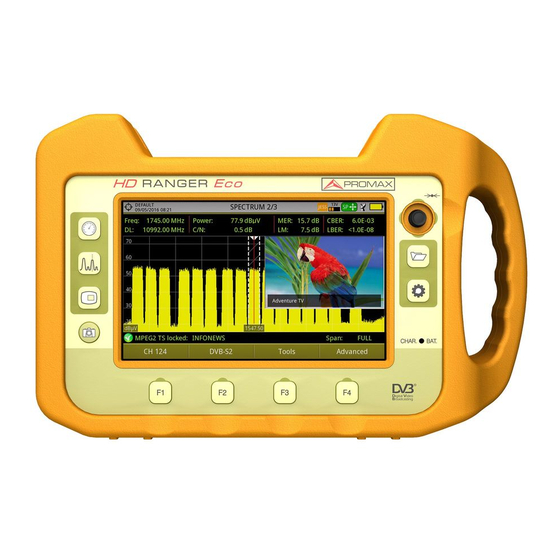
- Page 48 SPECTRUM + MEASUREMENT + TV (SPECTRUM 2/3) ► Figure 27. Selected installation; date and time. Number of view/total views. Joystick active mode; selected band; battery level. Measured values of the signal at the frequency/channel where is pointing the cursor. Image of the tuned signal. Spectrum in the band with the selected span.
- Page 49 FULL SPECTRUM (SPECTRUM 3/3) ► Figure 28. Selected installation, date and time. Number of view/total views. Joystick active mode; selected band; battery level. Spectrum in the band with the selected span. Centre frequency and cursor. It also shows the bandwidth of a digital signal locked.
- Page 50 FULL SPECTRUM (SPECTRUM 3/3) WITH MARKER ► Figure 29. Horizontal reference line: It shows level of signal. Vertical axis: It indicates the signal level. Vertical reference line: It indicates the frequency. SPAN: It is the frequency range displayed on the horizontal axis. Span values available changes according to Resolution Bandwidth selected.
- Page 51 use the joystick (left, right) in FR mode (tuning by frequency) or CH mode (tuning by channel). Marker: It is a special cursor that can be placed on a given frequency to check the power in this point. This option can be enabled using the "Marker" option from the Advanced menu ( key).
- Page 52 Signal status (searching/locked/multiplex name) and name of the selected service. Softkeys menus. Joystick functions: •Joystick up/down: It changes service. •Joystick left/right: It changes channel/frequency (depending on the tuning mode). TV + SPECTRUM + MEASUREMENT (TV 2/3) ► Figure 31. Selected installation; date and time. Number of view/total views.
- Page 53 Joystick functions: •Joystick up/down: It changes service. •Joystick left/right: It changes channel/frequency (depending on the tuning mode). TV + SERVICE DATA (TV 3/3) ► Figure 32. Selected installation; date and time. Tuned service image. Tuned service information. TYPE: Encoding type and video transmission rate. FORMAT: Resolution (horizontal x vertical), aspect ratio and frequency.
- Page 54 ONID: Identifier of the original network where the signal originates. TSID: Transport stream identifier. SID: Service Identifier. App. Type: Type of detected interactive service such as HbbTV, MHP and MHEG-5. It also shows the URL related to the interactive service in F4: Advanced - Discovered URLs.
- Page 55 AUDIO RADIO (RADIO 1/3) ► Figure 33. AUDIO RADIO + SPECTRUM + MEASUREMENT (RADIO 2/3) ► Figure 34. Cap. 4: RF SIGNAL TUNING February 2019...
- Page 56 AUDIO RADIO + RDS DATA (RADIO 3/3) ► Figure 35. RDS Data: PS: Programme service. PI: Programme Identification. PTY: Program type. UTC Time: Universal time. Local: Local time. ECC: Extended country code. LIC: Language Identification Code. TP: Traffic program. TA: Traffic announcement. MS: Music switcher.
-
Page 57: Extra Information
Extra Information 4.6.1 Generic Signal This is a special digital signal that the equipment does not demodulate. It can be used for special signals as DAB/DAB + or COFDM modulation with narrow BW. In this type of signal the user can select the signal bandwidth by accessing the "Signal Parameters"... - Page 58 satellites that avoid any possibility of error. When the signal is locked it identifies the satellite and shows on screen its name. Often satellite operators request to look for the Beacon signal, as a method of satellite identification. This signal is easily identified by the meter, because it has high resolution, high sensitivity and short sweep times.
- Page 59 More info about satellite signals in the application note “How to point a dish antenna” available on the PROMAX website. 4.6.4 IRG Descriptor The analyzer is compatible with IRG recommendations and it can extract the Carrier ID information and display it conveniently showing all the details. This information is useful to identify the interference, thanks to the carrier ID.
-
Page 60: Tools
5 TOOLS Introduction Tools are specific functions that complement the standard functions of the meter. These tools can help solve specific situations where the usual measurement is not enough. In this chapter, each of these tools is described in detail. It is advisable to know them to make the most of the meter potential. Tools are accessible by pressing the key . - Page 61 Each type of modulation is represented differently. A 16-QAM signal is shown on screen by a diagram of a total of 16 different zones and a 64-QAM signal is represented by a diagram of 64 different zones and so on. The constellation diagram shows in different colours the density of hits and includes features to zoom, move and delete the display on screen.
- Page 62 Screen Description ► Figure 39. Selected installation; date and time. Constellation window. The colour scale placed at the left side indicates the signal quality in a qualitative way by a gradation of colours proportional to the density of symbols concentrated in a given area. The colour scale ranges from black (no symbols) to red (highest density).
- Page 63 Joystick functions: •Joystick left/right: Frequency/Channel change (depending on the tuning mode). 5.2.3 Menu Options On the bottom of the screen there are four menus accessible via the function keys. It displays the channel / frequency where is pointing the cursor, accesses the tuning menu and allows selecting the channel plan.
-
Page 64: Lte Ingress Test
TV antenna or a passive shield in the way between the two antennas (TV and LTE). For more information, refer to application note “LTE Digital Dividend” available on the PROMAX website. 5.3.2 Operation The LTE Ingress Test is available to all Digital Terrestrial signals. - Page 65 Operation ► Connect the external LTE filter between the signal and the RF input. Tune the channel that is possibly affected by a LTE interference. Press the key : Tools. Select the LTE Ingress Test mode. Screen shows a confirmation message. Press on "Yes"...
- Page 66 Screen Description ► Figure 40. Selected installation; date and time. Elapsed time with filter enabled (ON). Measurement with LTE filter enabled: MER: Maximum and minimum MER for the TV channel tuned (the one probably affected by the LTE interference signal). LTE Power:Maximum and minimum power for the complete band, between minimum and maximum filter frequencies.
-
Page 67: Echoes
Softkeys menus. 5.3.3 Menu Options On the bottom of the screen there are four menus accessible via the function keys. It displays channel/frequency and access the tuning menu. It allows selecting the channel plan and the channel where apply the LTE ingress test. - Page 68 5.4.2 Operation Echoes function is available for DVB-T, DVB-T2 and DVB-C2 signals. Connect the RF input signal to the equipment. Tune a DVB-T, DVB-T2 or DVB-C2 digital signal at the terrestrial band. Press the Tools key. Select the Echoes option. The Echoes function of the tuned signal appears on screen.
-
Page 69: Attenuation Test
Softkeys menus. Joystick functions: •Joystick left/right (Channel/Frequency active mode): It changes the channel/frequency (according to the tuning type selected). •Joystick up/down (Echoes mode): It changes zoom. Remember to press the joystick to switch between the Echoes (EC) mode and the Channel/Frequency (CH/FR) mode. 5.4.3 Menu Options At the bottom of the screen there are four menus available via the function keys. - Page 70 Then it is necessary to Set References. This requires a signal generator. We recommend to use of one of the PROMAX signal generators: RP-050, RP- 080, RP-110 or RP-250 (depending on the frequency band). Connect the generator and the meter where the origin of the signal distribution is in the installation (antenna, headend, etc.) or connect the...
- Page 71 Screen Description ► Figure 42. Installation selected, date and time. Selected band; battery level. Status message depending on the attenuation level. Power level of the signal. Signal Frequency (MHz). Power level of the reference signal obtained when setting the reference and used to calculate the attenuation level (dBµV).
-
Page 72: Datalogger
5.5.3 Menu Options In the bottom of the screen are four menu accessible via the softkeys. Exits the tool. Pressing this option the current power values are captured and they are assigned as reference values. Access the Tools main menu. Access the Advanced menu. - Page 73 sub-folders would group the measurements for each apartment inside that building. Finally the test points would be the files with the measurements that would be taken in each one of the TV sockets inside the apartment. 5.6.2 Operation Creating a new datalogger ►...
- Page 74 Figure 43. Next, the user can select the terrestrial and/or satellite channel plan to use in the datalogger. The channel plans that are shown depends on the channel plans available for the current installation. Figure 44. February 2019 Cap. 5: TOOLS...
- Page 75 Figure 45. In the next window, the user can select an option to capture de service list when performing the datalogger (this option slows down the process but provides more information). Another option allows the user to enable a pause between channel plans (the process stops until the user wants to carry on).
- Page 76 Once a new datalogger is created or selected an already existing one, it shows the datalogger viewer screen and measurements of test points can start. If it is a new datalogger, in first place before starting the datalogger, the system will create a new test point (see next section). Test points represent a specific point such a TV antenna socket.
- Page 77 TER ICT and SAT ICT respectively. It is also possible to download Datalogger files to a PC by the NetUpdate software (free download on the PROMAX website). Once downloaded, the program can generate reports with these files. This is not possible with the datalogger files exported directly to a USB (without using NetUpdate).
- Page 78 Softkey menus. Current channel plan, progress bar in the current channel plan, selected test point. Channel, frequency and Downlink. Screen Description (Data Viewer) ► Figure 49. Channel Plan Data Viewer. Figure 50. Attenuation Test Data Viewer. Selected installation; date and time. February 2019 Cap.
- Page 79 Tab identifying the displayed test point. Current datalogger name. Selected band; battery level. Tab identifying each test point. Date and time when the datalogger was created. Number of channels locked (PASS) or not locked (FAIL). Data table with measurement data for each channel. In order from left to right: Colour identifying if the channel has been locked (WHITE) or not locked (RED) channel;...
-
Page 80: Screen And Data Capture (Export Key)
Datalogger Menu Options ► It cancels the datalogger. It pauses datalogger until the user resumes by pressing again. 5.6.4 Test & Go "Test & Go" function inside the "Datalogger" tool allows the user to create a quick datalogger by creating automatically a new datalogger, a new test point and then starting it. - Page 81 5.7.2 Operation Settings ► Press the "Management Installation" key for one second to enter “Preferences" menu. Go to the label " Tools" and select your option in "Export button". There are three options available: Screen Only, Data Only or Screen+Data. "Screen Only"...
-
Page 82: Explore Channel Plan
To see the capture in full screen just press the F4: Options key and then on the menu press "View in Full Screen". To exit the full screen view press any softkey. To delete or copy the capture to a USB stick, select the capture by pressing the joystick, and then select the appropriate option from the menu : File. - Page 83 Figure 51. After the exploration the following screen appears: Screen Description ► Figure 52. Spectrum and Measurement: It shows the cursor scrolling through each of the channels of the channel plan. On the bottom of the screen the channel and frequency appears next to the Power/Level and the C/N ratio. Cap.
- Page 84 Progress Bar: It shows the signal type detected and the scan progress in real time. At the end a box shows a message informing the exploration process has finished. Channel plan: At the end of the process it shows the channels that have been detected during the channel plan exploration.
-
Page 85: Field Strength
Field Strength 5.9.1 Description The Field Strength function allows the equipment to work as a field strength meter, measuring dBµV per meter. To perform this type of measurement is needed to enter the calibration parameters of the antenna being used to receive the signal. - Page 86 Figure 53. To save FSM data, go to "Tools", select "Datalogger" and then "New" to create a new datalogger. Keep in mind that the "FSM" tool does not demodulate any signal, it only detects the transmitted energy, so it is identied as a GENERIC signal.
- Page 87 5.9.4 Creating and Importing Calibration Tables The user can import the antenna calibration data obtained from the manufacturer. There is a template (available on the download area at PROMAX Cap. 5: TOOLS February 2019...
- Page 88 Next are the steps to fill in the template data and import them to the equipment: Antenna Generator ► Download the "Antenna XML Generator" template from the PROMAX website. In the "Model" box enter the name by which the antenna will be identified (maximum 8 characters).
- Page 89 In the drop down menu "Save as type" select the "XML Data" option. Then click "Save”. If a warning message shows up, click "Continue". Now the file is already generated with the selected name and the extension "xml". Now just import it to your equipment and load the calibration table of the antenna in the installation.
-
Page 90: Task Planner
Press : “Remove” key. 5.10 Task Planner 5.10.1 Description The Task Planner function allows the user to set-up a task list, selecting when to start, a repetition rate and other parameters. The equipment can be switched off after setting all parameters and it will wake-up, at the required time, to perform the scheduled tasks. - Page 91 Figure 57. The "Capture" option performs the capture task. The user can select the screen and type of capture. The screen options include any view in the three modes: Measurement, Spectrum or TV. The options for type of capture are: screen only, data only or screen+data (for details about capture refer to "Screen and data captures (Export button)"...
- Page 92 After selecting the type of task, check the box next to it and press :Timer to schedule the time to execute the task (see next section for details about the timer). When saving the timer for the task, the upper right corner shows an icon of a clock indicating that the equipment has tasks pending to execute.
- Page 93 or to indicate if something prevented its execution. To access this function, from Task Manager, press : Task and then "View Log...". NOTE: The equipment can be turned off after task planning as it will automatically turn on when the time to task execution comes. Two tasks cannot be executed simultaneously.
- Page 94 Repeat every: The task repeats each cycle of time (days, hours and minutes). Stop •Manual: The user finishes the task. •On date: The user selects the stop date for the task (day / month / year) and (hour: minute). •Repeat a number of times: The task execution ends after the number of times set.
-
Page 95: Installations Management
6 INSTALLATIONS MANAGEMENT Introduction The Installations Management is a program embedded in the equipment that allows the user to easily create a file (installation) to individually store and manage data for each installation. Measurements, channel plans, screenshots and any other data associated with the installation will be stored in the folder corresponding to that installation. -
Page 96: Installation Management
There are the following options: Load : It loads the selected installation. To select a installation from the list, place the cursor on the installation and press the joystick, then press “Load” to load it. Once loaded, the name of the installation appears on the upper left corner of the screen, accompanied by the symbol , that means that is the current installation. - Page 97 Figure 62. The window is divided into three areas: General Data: The first line shows general information about the installation. The second line shows information about the selected file. Data fields are: Created: Date and time the current installation was created. Size: Data size of the current installation.
- Page 98 Menu Options ► The installation manager menu has four options linked with the softkeys. They are described below: Filter by Type: It shows all available file types in the current installation and the amount of them between brackets. User can filter by file type.
-
Page 99: New Installation
to the selected satellite channel plan from the list of diseqc programs available for the current installation. •Open File: This options appears if the file type selected is datalogger, data capture or signal monitoring. In case of data capture (if the capture was done in the Spectrum Analyzer mode) shows the spectrum reference. -
Page 100: Importing Data From Usb
Archive: It compresses (using the ZIP algorithm) the selected installations to save more space. A zipped installation shows a box icon at the left side in the list of installations. A zipped installation can be loaded as anyone else, but the load time can be slightly higher because previously it is unzipped automatically. - Page 101 Figure 63. Import Files window If the file import is successful then a window shows a confirmation message. Cap. 6: INSTALLATIONS MANAGEMENT February 2019...
-
Page 102: Connecting To External Devices
7 CONNECTING TO EXTERNAL DEVICES Description The meter can interact with external devices, sharing information through its interfaces. Connection types are: Input/output data via mini-USB port. Video/Audio analogue input via V/A port. DiSEqC, SCD/EN50494 standard (also known as SatCR) and SCD2/ EN50607 standard (also known as JESS) interface via RF connector. - Page 103 Press the Installations key and check the installation to download some of its data. Press the key : Manage to access the data of the selected installation. Press the key : Filter by type to select the type of list to view (list of all the files, only screenshots, only channel plans, only dataloggers or only DiSEqC commands).
- Page 104 Open/Receive/Save/Print data files captured with the Datalogger function. Transmit/Receive/Edit/Save channel plans. Create/Edit channel plans. For more information about the NetUpdate program, see the user's manual, which is available on the PROMAX website. February 2019 Cap. 7: CONNECTING TO EXTERNAL DEVICES...
-
Page 105: Input Jack Connector
Run NetUpdate on your PC. If connection is successful, a confirmation window will appear and you will be able to see the meter data in the main NetUpdate window (for details about NetUpdate program, download the manual from the PROMAX website). Input Jack Connector The V/A input connector allows connecting a video/audio analogue input signal. -
Page 106: Rf Connector
With the option : Aspect, you can select the aspect ratio of the image, between 4:3 and 16:9. NOTE: If the equipment is displaying an external analogue video, it will not switch to internal video mode anymore when that external video is disconnected or lost. - Page 107 (for more information about DiSEqC commands and programs download document from PROMAX website). 7.4.2 SCD / EN50494 (SatCR) Commands By means of function SCD/EN50494 (international standard, also known as SatCR) it is possible to control the devices of a TV satellite installation that are compatible with this standard, which allows to concentrate downlink frequencies (slots) by an only cable.
- Page 108 Figura 64. The configuration window shows the options that user can modify: number of slots, slot selected, device address, pilot signal activation (when activating the SatCR device located in the headend, it emits a pilot signal with constant level for each downlink frequency to identificate available channels), selected satellite and frequency step.
- Page 109 Press the Spectrum key to access the spectrum analyzer mode. Press the Settings key and select the satellite band. From the Settings menu, select the polarization (horizontal/vertical) and the satellite band (high/low). If necessary, enable the Supply output and select the supply voltage for the LNB.
- Page 110 Figura 66. Once it is configured, the user, through the key "Tuning" can select the user band. User frequency tuned is stored for each User band (UB) and it is restored each time the multiswitch is being configured. NOTE: When not detecting any SCD2 receiver, the function enters in a more basic mode, allowing sending configuration commands even with nothing connected.
-
Page 111: Specifications
8 SPECIFICATIONS General ► Inputs and Outputs Parameter Value Additional Data RF Input Input Connector F male 75 Ω Maximum Signal 130 dBμV Maximum Input Voltage 50 V rms DC a 100 Hz; powered by the AL-103 power charger 30 V rms DC a 100 Hz;... - Page 112 > 2.5 hours in continuous mode No EXTERNAL supply active Recharging time 3 hours up to 80% With meter off External Voltage 12 V DC Only using PROMAX supplied accessories Consumption 40 W Auto Power Off Programmable After the selected amount of minutes...
-
Page 113: Measurement Mode
Parameter Value Additional Data 1x AD-057 "F"/f-"F"/f adapter 1x CA-005 Mains cord 1x CB-084 Rechargeable Li+ battery 7,2 V 13 Ah Built-in 1x DC-300 Transport belt 1x DC-302 Carrying bag 1x DG0257 Quick Reference Guide 1x MN-001 Monopod NOTE: It is recommended to keep all the packing material in order to return the equipment, if necessary, to the Technical Service. - Page 114 Parameter Value Additional Data Displayed Data Numeric and level bar Carriers 1k, 2k, 4k, 8k, 8k+ EXT, 16k, 16k+ EXT, 32k, 32k+ EXT Guard Interval 1/4, 19/256, 1/8, 19/128, 1/16, 1/32, 1/128 Bandwidth 5, 6, 7 and 8 MHz Spectral Inversion ON, OFF Auto Pilot Pattern...
- Page 115 Parameter Value Additional Data Code Rate PLP 2/3, 3/4, 4/5, 5/6, 8/9, 9/10 PLP Constellation 64 QAM, 256 QAM, 1k QAM, 4K QAM Dslice PLP 0 - 256 Auto PLP ID 0 - 256 Cell ID Detected from transmitter station Network ID Detected from transmitter station C2 System ID...
- Page 116 Parameter Value Additional Data Margin of Power Measurement 35 dBμV - 115 dBμV 2150 MHz, 27500 kSps, CR=2/3 Roll-off: 0,20 QPSK Sensitivity (QEF): 26 dBμV 8PSK Sensitivity (QEF): 30 dBμV 8PSK: 24 dBμV a 2.15 GHz / 2 MSs; 34 dBμV a 2.15 GHz / 27 MSs Measurements Power, CBER, LBER, MER, C/N, BCH ESR, Wrong Packets and Link Margin...
-
Page 117: Spectrum Analyzer Mode
Spectrum Analyzer Mode ► Digital Signal Parameter Value Additional Data General Parameters Markers It displays frequency, level indication, level difference, frequency difference Reference Level 60 dBμV - 135 dBμV Adjustable in steps of 5 dB Spectrum Range Span, dynamic range and reference level are variable by means of arrow cursors Terrestrial... -
Page 118: Tv Mode
Parameter Value Additional Data Accuracy ±1,5 dB 20 dBμV - 130 dBμV @ 990 MHz 10 μV - 3.16 V 22 °C ± 5 °C Out of range indication <, > Satellite Tuning Range 950 - 2150 MHz Tuning Mode Intermediate frequency or downlink Channel plan configurable Tuning Resolution... -
Page 119: Tools
Parameter Value Additional Data Packets 188 or 204 bytes Automatic detection Video Info Type, bitrate, format, aspect ratio, frequency, profile, PID Service Info Network, provider, NID, ONID, scrambled/free, TSID, SID, LCN Audio Info Type, bitrate, format, frequency, mono/stereo, language, PID Tools ►... - Page 120 ► Datalogger Parameter Value Additional Data Stored Data Signal type, modulation parameters, In case of DVB-T2 signal it stores all all measures available for the information from PLPs. detected signal type, and time stamp, PSI info for each measured channel Timestamp Date and time at each measured channel...
-
Page 121: Maintenance
9 MAINTENANCE Instructions for Returning by Mail Instruments returned for repair or calibration, either within or out of the warranty period, should be sent with the following information: Name of the Company, name of the contact person, address, telephone number, receipt (in the case of coverage under warranty) and a description of the problem or the service required. - Page 122 Cleaning the Plastic Case ► The equipment has to be disconnected before cleaning the case. The case must be cleaned with a solution of neutral soap and water, using a soft cloth dampened with this solution. Before use, the equipment has to be completely dry. Never clean with abrasive soaps, chlorinated solvents or aromatic hydrocarbons.
-
Page 123: Additional Information
ADDITIONAL INFORMATION Multimedia Content On the PROMAX channel on Youtube you can find video tutorials and other audiovisual documents related to the field strength meter. Name Link PROMAX channel on YOUTUBE https://www.youtube.com/user/PROMAXElectronics Playlist: Field Strength Meter Tutorials https://www.youtube.com/ watch?v=48klYEAR_ZU&list=PL3hht4WG655S6PXlzd3G9lt... - Page 124 Name Link Linkedin https://www.linkedin.com/company/1493234/ Facebook https://www.facebook.com/promaxelectronics/ Google https://plus.google.com/+PromaxelectronicsGlobal February 2019 Annex i: ADDITIONAL INFORMATION...
-
Page 125: Index
ii INDEX Analogue Signal 37 Antenna remove 94 Aspect Ratio 37 Audio 37 Audio Signal 36 Audio Tone 36 Band selection 20 Battery Time 25 Beacon signal 52 Brightness 23, 25 Centre Frequency 45 Channel Plan Adding 92 Colour System 23 Cursor 44 Dashed BW 37 Detector Type 37... - Page 126 Locking a Signal 51 Marker 36, 45 Marker Trace 36 Max. Hold 36 Measurement Mode Screens 38 Min. Hold 36 Minimal FM Level 26 Minimal Satellital Power 26 Minimal Terrestrial Level 26 Minimal Terrestrial Power 26 Netupdate connection 98 NTSC 23 Offset 26 PAL 23 Persistence of Spectrum 37...
- Page 127 Vertical Range 37 Video & Audio Settings 23 Volume 23 Index 4 February 2019...
- Page 128 PROMAX ELECTRONICA, S.L. Francesc Moragas, 71-75 08907 L’HOSPITALET DE LLOBREGAT (Barcelona) SPAIN Tel: 93 184 77 00 * Tel. Intl.: (+34) 93 184 77 02 Fax: 93 338 11 26 * Fax Intl.: (+34) 93 338 11 26 http://www.promaxelectronics.com e-mail: promax@promaxelectronics.com...
Need help?
Do you have a question about the HD RANGER Eco and is the answer not in the manual?
Questions and answers