Table of Contents
Advertisement
Quick Links
Advertisement
Table of Contents

Related Manuals for Promax CABLE RANGER


Summary of Contents for Promax CABLE RANGER
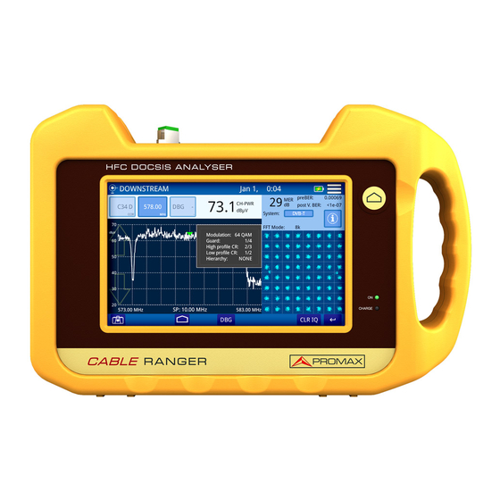
- Page 1 CABLE RANGER FIBER-COAXIAL DOCSIS ANALYZER -0 MI2125 -...
- Page 2 SAFETY NOTES Read the user’s manual before using the equipment, mainly "SAFETY RULES" paragraph. The symbol on the equipment means "SEE USER’S MANUAL". In this manual may also appear as a Caution or Warning symbol. WARNING AND CAUTION statements may appear in this manual to avoid injury hazard or damage to this product or other property.
- Page 3 SAFETY RULES * The safety could not be assured if the instructions for use are not closely followed. * Use this equipment connected only to systems with their negative of measurement connected to ground potential. * The AL-103 external DC charger is a Class I equipment, for safety reasons plug it to a supply line with the corresponding ground terminal.
- Page 4 SAFETY SYMBOLS DESCRIPTIVE EXAMPLES OF OVER VOLTAGE CATEGORIES * Cat I: Low voltage installations isolated from the mains. * Cat II: Portable domestic installations. * Cat III: Fixed domestic installations. * Cat IV: Industrial installations. CAUTION: The battery used can present danger of fire or chemical burn if it is severely mistreat.
-
Page 5: Table Of Contents
TABLE OF CONTENTS 1. INTRODUCTION ..................1 1.1. Description .................... 1 2. SETTING UP ....................3 2.1. Package Content ..................3 2.2. Power ....................3 2.2.1. First Charge ......................3 2.2.2. Charging the Battery ....................3 2.2.3. Charge / Discharge times ................... 4 2.2.4. -
Page 6: Introduction
FIBER-COAXIAL DOCSIS ANALYZER CABLE RANGER 1 INTRODUCTION Description RANGER is the latest introduction in our CATV analyzer product CABLE range. It is an hybrid analyzer (for both fibre optics and coaxial cable) for the installation, configuration and maintenance of interactive video and data services at high speed over TV networks based on the DOCSIS standard. - Page 7 Figure 1. The Spectrum Analyzer function provides an analysis of the full band and allows changing the reference level and the span among others. The Scan function shows the level of all active channels in the channel plan through a bar chart. The TILT function measures the tilt in dB obtained from the difference in level between four carriers.
-
Page 8: Setting Up
2 SETTING UP Package Content Check that your package contains the following elements: RANGER Analyser. CABLE External DC charger. Power cord for external DC charger Car lighter charger. "F" Adapters •"F" / f - BNC / f Adapter. (2 u.). •"F"... -
Page 9: Charge / Discharge Times
Connect the DC power adapter to the equipment through the power connector on the left side panel (see figure). Figure 2. Then connect the DC power adapter to the mains via the mains cord. Ensure that your mains voltage is compatible with the adapter voltage. For a fast charging of the battery is necessary to switch off the equipment. -
Page 10: Usage Tips
Usage Tips The battery is losing storage capacity as you go through its life. Contact your PROMAX distributor when necessary to replace the battery. To prolong battery life the user should follow these tips: In case of providing a long inactivity period of the equipment it is advisable to make every 3 months a charge / discharge cycle and a subsequent partial charge (40% aprox.). -
Page 11: Equipment Details
Equipment Details Figure 3. Front View. April 2018 Chapter 2: SETTING UP... - Page 12 Figure 4. Side View. Chapter 2: SETTING UP April 2018...
-
Page 13: Switching On / Off
Figure 5. Top View. Switching On / Off Switching On: ► Press the on/off button located on the side of the equipment. The boot screen appears. After the system load, the last screen before shutdown appears. April 2018 Chapter 2: SETTING UP... -
Page 14: Icons Table
Switching Off: ► There are two options : Option 1: Press the on/off button located on the side of the equipment. A gray screen with a red power off icon will appear. Click on this icon to turn off the equipment or outside the icon to cancel power off. Option 2: Press on the menu icon located at the screen upper right corner. -
Page 15: Controls
Controls The equipment can be fully operated using the touch panel.. These actions can be done through the touch panel: Menu Selection. Frequency or channel selection. Frequency or channel scroll. Reference level scroll. SPAN selection. Virtual keyboard writing (numerical and alphabetical). General Settings From the Home screen, clicking on the menu icon you Access General... - Page 16 Click here to download file with the latest firmware available or download from the download area at PROMAX website (www.promaxelectronics.com). Copy the update file (update_usb.tar) to the flash drive root (do not unzip the file). Turn OFF the RANGER and insert the flahs drive into the the USB CABLE port.
-
Page 17: Measurement
3 MEASUREMENT Spectrum Analyzer (cable & FO) Description ► The SPECTRUM ANALYZER function shows on screen the spectrum of the signal received through the input connector. This function shows signals in frequency band so user can detect any problem and also measures level and demodulates signal. User can select span and reference level by selecting a frequency or channel. - Page 18 Screen Description ► Figure 7. Arrows to increase / decrease value of the selected parameter (channel or frequency). When a parameter is selected its background color is stronger. Selected channel. When pressing on it deploys a list of available channels. Selected channel plan.
-
Page 19: Scan (Cable & Fo)
Options Menu ► There are some options at the bottom of the screen: : Screenshot. DEMOD A: Demodulator (refer to "Demodulator " chapter). Settings ► Click on the MENU icon at the upper right corner to access the Settings menu. The SPECTRUM ANALYZER function has these options: Edit channel plan: It allows you to edit a channel plan and DBG (refer to "Edit Channel Plan"... - Page 20 Operation ► Connect signal to the input connector: Cable: universal connector for F/F or F/BNC adapter. Fiber Optics: SC-APC connector. Access home screen by pressing the HOME key. Select SCAN function according to input signal (cable or fiber). Press function on the left side of the screen for FIBER OPTICS or on the right side for CABLE.
- Page 21 Selected channel plan. When pressing on it deploys a list of available channel plans. Frequency selected. When pressing on it pops up a virtual numeric keypad to edit frequency. It shows if the selected channel is digital (D) or analogue (A). Channel bandwidth power.
-
Page 22: Tilt (Cable & Fo)
Settings Menu ► Click on the MENU icon at the upper right corner to access the Settings menu. The SCAN function has these options: Edit channel plan: It allows you to edit a channel plan and DBG (refer to "Edit Channel Plan" chapter). Units: It allows you to select a mesurement unit for power (dBuV, dBmV, dBm). - Page 23 Operation ► Connect signal to input connector: Cable: universal connector for F/F or F/BNC adapter. Fiber Optics: SC-APC connector. Access home screen by pressing the HOME key. Select the SCAN function according to input signal (cable or fiber). Press function on the left side of the screen for FIBER OPTICS or on the right side for CABLE.
-
Page 24: Docsis Analyzer
TILT: Inclination rate in dB per MHz. Power difference between P1 and P4. Full band RF cable power. In FIBER OPTICS it also shows full band of fiber optics cable. Arrows to change reference level. Bar graph showing signal level for each pilot signal and TILT. Options Menu ►... -
Page 25: Docsis Downstream Spectrum Analyzer (Cable & Fo)
DOCSIS REGISTERING allows you to register your equipment in the network. Once registered you can check it with IPTV, VoIP and BROWSER tools. Operation ► Connect signal to the input connector: Cable: universal connector for F/F or F/BNC adapter. Fiber Optics: SC-APC connector. Access home screen by pressing the HOME key. - Page 26 Screen Description ► Figure 10. Arrows to increase / decrease value of the selected parameter (channel or frequency). When a parameter is selected its background color is stronger. Selected channel. When pressing on it deploys a list of available channels. Selected channel plan.
- Page 27 Arrows to increase / decrease span. Current span. Bandwidth resolution. Selected marker for channel / frequency. Options Menu ► There are some options at the bottom of the screen: : Screenshot. CLEAR: It clears spectrum trace (this options is available if trace was hold previously).
-
Page 28: Docsis Bonding Group (Cable & Fo)
3.4.2 (cable & FO) DOCSIS BONDING GROUP Description ► DBG function shows power for each channel and carrier belonging to DOCSIS BONDING GROUP. Screen Description ► Figure 11. Power for each DBG carrier. Arrow on the bar indicates carrier selected. Constellation Diagram. -
Page 29: Ranging (Cable)
Settings ► Click on the MENU at the upper right corner to access the Settings menu. The DOCSIS BONDING GROUP function has these options: Edit channel plan: It allows you to edit a channel plan and DBG (refer to "Edit Channel Plan" chapter). CM Information: It shows information about software and MAC address of CableModem. -
Page 30: Docsis Registering (Cable)
Downstream ► System: Transmission standard. SR: Symbol Rate. MOD: Modulation. MER: Modulation Error Ratio. PreBER: Error ratio before correction. PostBER: Error ratio after correction. Interleaver: Improvement of error correction performance. Offset: Offset for tuning frequency. Upstream ► UCD: Upstream Channel Descriptor. FR: Channel frequency. - Page 31 Screen Description ► Figure 13. Downstream CH: Channel. F: Frequency. PWR: Power. MER: Modulation Error Ratio. MOD: Modulation. Upstream UC: Upstream Channel. F /BW: Frequency and bandwidth channel. PWR: Power. ATT: Channel attenuation. SR: Symbol Rate. IP REPORT: Report showing IP devices when registering. April 2018 Chapter 3: MEASUREMENT...
-
Page 32: Iptv (Cable)
Options Menu ► There are some options at the bottom of the screen: : Screenshot. DBG: It opens DOCSIS BONDING GROUP function (see previous section). Test IP: It opens IP TEST (VoIP/IPTV)function (see next section). BROWSER: It opens DOCSIS BROWSER function. Setting Menu ►... - Page 33 Screen Description ► Figure 14. Graphic with nodes and time (ms) of test signal. It allows you to enter an IP address where sending the test signal. Node: node selected. It shows some parameters obtained from test: IP address: Test IP. Latency: Delay due to transport or processing.
-
Page 34: Voip (Cable)
Settings Menu ► Click on the MENU icon at the upper right corner to access the Settings menu. The IPTV function has these options: Nominal Polling Interval: Time interval (ms) between successive requests. RTPS (Real Time Polling Service): It enables / disables RTPS service. 3.4.6 VoIP (cable) Description... - Page 35 Screen Description ► Figure 15. It shows values obtained during test. PLR (Packet Loss Rate): It is the percentage of lost packets over total sent packets. R VALUE: It shows a number or score, that is used to quantitatively express the subjective quality of speech in communications systems. Can range from 1 (worst) to 100 (best).
-
Page 36: Docsis Browser (Cable)
Options Menu ► There are some options at the bottom of the screen: : Screenshot. LOGGER: It creates a datalogger with measurement data. REGISTER: It returns to the DOCSIS REGISTERING function (see previous section). IPTV: IPTV function opens (see previous section). Settings Menu ►... - Page 37 Screen Description ► Figure 16. Barra de Navegación. Previous page. Next page. Reload page. URL bar: enter address and press Go. Keyboard: It shows virtual keyboard to enter URL. User / Pass : Password and user to enter CM administrator page. Browser screen .
-
Page 38: External Cm / Upstream Spectrum (Cable)
External CM / Upstream Spectrum (cable) Description ► The External CM / Upstream Spectrum function extracts a sample of the upstream signal and displays its spectrum on the screen. Connect the CABLEMODEM to the "EXT CM" input and the cable from the CMTS to the "RF" input. - Page 39 Screen Description ► Figure 17. Arrows to increase / decrease value of the selected parameter (channel or frequency). When a parameter is selected its background color is stronger. Frequency selected. When pressing on it pops up a virtual numeric keypad to edit frequency.
-
Page 40: Upstream Test (Cable)
Settings Menu ► Click on the MENU icon at the upper right corner to access the Settings menu. The EXT. CM / UPSTREAM function has these options:. Frequency step: It allows you to select frequency step (0.25 MHz, 1 MHz, 8 MHz, other value). Full span maximum frequency: It allows you to select full span maximum frequency (900 MHz, 1700 MHz, other value). - Page 41 Screen Description ► Figure 18. Parameters to set UPSTREAM signal: Frequency mode: Select between Sweep or Fix. Frequency start: Select start frequency (only for Sweep mode). Frequency stop: Select stop frequency (only for Sweep mode). Frequency: Select frequency (only for Fix mode) Power: Select power level for signal.
-
Page 42: Ac / Dc Input Voltage (Cable)
Settings Menu ► Click on the MENÚ icon at the upper right corner to access the Settings menu. The UPSTREAM TEST GENERATOR function has these options: Units: It allows you to select measurement unit for power (dBuV, dBmV, dBm). CM Information: It shows information about software and MAC address of CableModem. -
Page 43: Optical Power Meter (Fo)
Screen Description ► Figure 19. RF-PWR: Full bandwidth power Vin DC: DC input voltage. Vin AC: AC input voltage and frequency. Settings Menu ► Click on the MENU icon at the upper right corner to access the Settings menu. The INPUT AC/DC VOLTAGE function has these options: Units: It allows you to select measurement unit for power (dBuV, dBmV, dBm). - Page 44 Operation ► Connect signal to the input connector: Cable: universal connector for F/F or F/BNC adapter. Fiber Optics: SC-APC connector. Access home screen by pressing the HOME key Select OPTICAL POWER METER function. OPTICAL POWER METER, function opens. Press HOME key to get back to the main screen.
- Page 45 Options Menu ► There are some options at the bottom of the screen: : Screenshot. DATALOGGER: It creates a datalogger with measurement data. REFERENCE: It allows you to save current power value as reference value. Settings Menu ► Click on the MENÚ icon at the right corner to access the Settings menu.
-
Page 46: Tools
4 TOOLS Edit Channel Plan Description ► Channel plan editor allows to edit and create channel plans, and also to edit DBG (Docsis Bonding Group) channels. Operation ► Channel plan editor is available in ANALYZER and SCAN . Select channel plan on main screen. Access menu by pressing on Press on "Edit Channel Plan"... - Page 47 Screen Description ► Figure 21. Channel plan selected. Press on this box to select another channel plan. Go to: Press on this box to switch between CH (channel) and FR (frequency) and to select a channel or frequency. Channel table. Parameters on channel table are: CH: Channel.
- Page 48 Options Menu ► There are some options at the bottom of the screen: EDIT DBG: Opens the DBG editor screen (see next section. : Back to main screen. Settings Menu ► Click on the MENU icon at the upper right corner to access the Settings menu.
- Page 49 EDIT DOCSIS BONDING GROUP Screen Description ► Figure 22. Edit Docsis Bonding Group: Press on the box to select DBG to edit. Add channel to DBG: Press on arrows or on the box to select one channel and then press on ADD to add to DBG. Remove channel to DBG: Press on arrows or on the box to select one channel and then press on REMOVE to remove from DBG.
- Page 50 Create a Channel Plan from an existing one ► Figure 23. Chapter 4: TOOLS April 2018...
- Page 51 Figure 24. Press on box "Model" to select a channel plan as a model to create a new one. Press on box "Name" to give a name to the new channel plan. Press "OK" to create a new channel plan or "Cancel" to exit. At the next screen, press on "Add Channel", "Remove Channel"...
- Page 52 Create automatically a channel plan from HFC network ► Figure 25. Chapter 4: TOOLS April 2018...
- Page 53 Figure 26. Connect to the HFC network. Press on box “Model” to select a channel plan as a model to create a new one. Press on “Start measuring”. When finish press on "Name" box to edit the channel plan name. Press on "Save channel plan"...
-
Page 54: Demodulator
Create a new Channel Plan from scratch ► Figure 27. Press on box "Name" to give a name to the new channel plan. At the next screen, press on “Add Channel”, “Remove Channel” to edit channel plan. When finish, press on “Save channel plan” to save changes or “Cancel”... - Page 55 Operation ► available digital signals functions SPECTRUM DEMODULATOR ANALYZER and SCAN Select channel or frequency and tune it. Press on "DEMOD" option. Screen Description ► Figure 28. Demodulated Signal Data. MER for tuned channel. pre-BER (BER before correction). post-BER (BER after correction). Transmission standard.
-
Page 56: Analog Video Carrier / Hum
Options Menu ► There are some options at the bottom of the screen: CLR IQ: It clears constellation . Back to previous screen. Analog Video Carrier / HUM Description ► The equipment can measure video carrier signal level, Video/Audio and C/N ratio and HUM in analog mode. -
Page 57: Screenshot
Screen Description ► Figure 29. Analogue Video Carrier / HUM. Vídeo c.LVL: Level of video carrier. Audio c.LVL: Level of audio carrier. V/A: Video/Audio ratio. C/N: Carrier/Noise ratio. HUM: Audio carrier. CTB/CSO: Intermodulation product measurement. Audio OFF/ON: It enables / disables audio and to set audio level. Screenshot Description ►... - Page 58 Operation ► Figure 30. Screenshot is available almost all functions. To take a screenshot press on photo camera icon at the lower left corner. It pops up a window with a screenshot miniature and some options: “Save and close”, “Save and go to gallery” and “Cancel”. Press your option. To access the photo gallery with all the screenshots, from home screen press on icon at the lower left corner.
-
Page 59: Datalogger
To remove a single screenshot, see the screenshot fullscreen, press on option menu and then on “Remove” and confirm. Datalogger Description ► Datalogger function can logger automatically several measurements depending on the selected function, including signal level and channel power, carrier/noise, BER and MER for all channels in a specific channel band. - Page 60 After finish, press on "Save and close", "Save and go to datalogger" or "Cancel". To access datalogger, go to home screen and press on icon at the lower left corner. Datalogger are classified by function. Press on any folder, then press on the datalogger to see data. To remove a folder with dataloggers or a single datalogger, press on the menu option and then on “Remove”.
-
Page 61: Specifications
5 SPECIFICATIONS Spectrum Analyzer ►Frequency Parameter Value Additional Data Tuning Range From 5 to 1700 MHz 1200 MHz/ DOCSIS, 1700 MHz/DOCSIS 3.1 Tuning Mode By Frequency or by channel Frequency step 0 KHz Bandwidth resolution 230 kHz, 2 MHz Accuracy 20 ppm Sweep time 600 ms full band... - Page 62 Parameter Value Additional Data Pre BER (Before RS): From 10 E-2 to Post BER (After FEC): From 10 E-2 to 10 E-10 10 E-10 Constellation Diagram For all systems with x2, x4 zoom Lock range -20 dBmV to 60 dBmV ►Measurements: Analog Channel Demodulation Parameter Value...
- Page 63 ►Amplitude Parameter Value Additional Data Dynamic range -50 dBmV to 60 dBmV Screen range: 50 dB Max Input level: 70 dBmV Resolution: 0.1 dB Accuracy: ± 2 dB Input impedance: 75 Ohms Units: dBmV, dBuV, dBm ►Measurements: DIGITAL Channel Parameter Value Additional Data Power...
- Page 64 ►Configuration Menu Parameter Value Additional Data Channel Plan Standard TV Channel plans CCIR,EIA,HRC,IRC,OIRL,FCC up to 10 Customized Channel plan Up to 30 Units dBmV, dBuV, dBm Reference Line from –60 dBmV to 120 dBmV Units dBmV, dBuV, dBm Reference Line from –60 dBmV to 120 dBmV Thresholds Max and Min limits for quality evalua-...
- Page 65 ►Configuration Menu Parameter Value Additional Data Units dBmV, dBuV, dBm Select two pilots for Tilt Pbottom / Ptop DOCSIS Analyzer ►Frequency Parameter Value Additional Data Tuning Range From 90 to 1700 MHz Tuning Mode By Frequency or by channel Frequency step 10 KHz Bandwidth resolution 230 kHz, 2 MHz...
- Page 66 ►Downstream DOCSIS Channel Demodulation Parameter Value Additional Data Systems compatibility: DOCSIS 2.0, DOCSIS 3.0 From 27 dB to 40 dB Pre BER (Before RS): From 10 E-2 to Post BER (After FEC): From 10 E-2 to 10 E-10 10 E-10 Constellation Diagram For all systems with x2, x4 zoom Lock range...
- Page 67 Parameter Value Additional Data Modulation QPSK, 16QAM, 32QAM, 64QAM From 160 ksym/s to 5120 ksym/s ►Configuration Menu Parameter Value Additional Data Units: dBmV, dBuV, dBm CM information: SW MODEM, MAC ADDRESS External Cable Modem Upstream Spectrum Analyzer ►Frequency Parameter Value Additional Data Tuning Range: From 5 to 85 MHz or 5 to 200 MHz...
- Page 68 Input Voltage and RF Power Meter ►RF Power Measurement Parameter Value Additional Data Frequency band 5-1700 MHz Power accuracy: ± 3 dB ►Input Voltage Measurement Parameter Value Additional Data 1-90 V 1-30 V, Frequency measurements from 10 Hz to 200 Hz, ±2 % accuracy ►Configuration Menu Parameter...
- Page 69 General Specifications ►Inputs and Outputs Parameter Value Additional Data Coax 1 Coax 2 Optical USB 1 USB 2 Ethernet Touch Monitor Display ►Mechanical Features Parameter Value Additional Data Dimensions 290 x 185 x 65 Weight 1.6 kg ►Power Supply Parameter Value Additional Data Internal battery...
- Page 70 NOTE: Equipment specifications are set in these environmental operating conditions. Operation outside these specifications are also possible. Please check with us if you have specific requirements. ►Included Accesories Parameter Value Additional Data DC Adapter, DC car adapter, F connector (2), carrying case, suitcase, Quick reference guide Chapter 5: SPECIFICATIONS April 2018...
-
Page 71: Maintenance
6 MAINTENANCE Instructions for Returning by Mail Instruments returned for repair or calibration, either within or out of the warranty period, should be sent with the following information: Name of the Company, name of the contact person, address, telephone number, receipt (in the case of coverage under warranty) and a description of the problem or the service required. - Page 72 Cleaning the Plastic Case ► The equipment has to be disconnected before cleaning the case. The case must be cleaned with a solution of neutral soap and water, using a soft cloth dampened with this solution. Before use, the equipment has to be completely dry. Never clean with abrasive soaps, chlorinated solvents or aromatic hydrocarbons.
- Page 73 PROMAX ELECTRONICA, S.L. Francesc Moragas, 71-75 08907 L’HOSPITALET DE LLOBREGAT (Barcelona) SPAIN Tel. : 93 184 77 00 * Tel. Internacional: (+34) 93 184 77 02 Fax : 93 338 11 26 * Fax Internacional: (+34) 93 338 11 26 http://www.promax.es...
Need help?
Do you have a question about the CABLE RANGER and is the answer not in the manual?
Questions and answers