Promax RANGER mini User Manual
Digital multi system analyzer
Hide thumbs
Also See for RANGER mini:
- Quick reference manual (8 pages) ,
- Quick reference manual (12 pages)

Related Manuals for Promax RANGER mini


Summary of Contents for Promax RANGER mini
- Page 1 Test Equipment Depot - 800.517.8431 - 99 Washington Street Melrose, MA 02176 - TestEquipmentDepot.com mini RANGER DIGITAL MULTI SYSTEM ANALYZER -0 MI2150 -...
- Page 2 SAFETY NOTES Read the user’s manual before using the equipment, mainly "SAFETY RULES" paragraph. on the equipment means "SEE USER’S MANUAL". In this manual may The symbol also appear as a Caution or Warning symbol. WARNING AND CAUTION statements may appear in this manual to avoid injury hazard or damage to this product or other property.
- Page 3 SAFETY RULES * The safety could not be assured if the instructions for use are not closely followed. * Use this equipment connected only to systems with their negative of measurement connected to ground potential. * The AL-103 external DC charger is a Class I equipment, for safety reasons plug it to a supply line with the corresponding ground terminal.
- Page 4 SAFETY SYMBOLS DESCRIPTIVE EXAMPLES OF OVER VOLTAGE CATEGORIES * Cat I: Low voltage installations isolated from the mains. * Cat II: Portable domestic installations. * Cat III: Fixed domestic installations. * Cat IV: Industrial installations. CAUTION: The battery used can present danger of fire or chemical burn if it is severely mistreat.
-
Page 5: Table Of Contents
TABLE OF CONTENTS 1. INTRODUCTION ..................1 1.1. Description .................... 1 2. SETTING UP ....................3 2.1. Package Content ..................3 2.2. Power ....................3 2.3. Equipment Details .................. 6 2.4. Switching On / Off .................. 8 2.5. Icons Table ................... 9 2.7. -
Page 6: Introduction
In addition, the instrument provides Ethernet and USB port slots to connect to external devices, to download data and to update firmware. Here are some of the most important functions in the RANGER mini. Chapter 1: INTRODUCTION September 2018... - Page 7 Figure 1. The Downstream Spectrum Analyzer function provides an analysis of downstream spectrum in the band between 5 and 2700 MHz. It can demodulate a signal and show its constellation. Reference level and span can be set by user. The Upstream function provides an analysis of upstream spectrum in the band between 5 and 200 MHz.
-
Page 8: Setting Up
2 SETTING UP Package Content Check that your package contains the following elements: mini Analyser. RANGER External DC charger. Power cord for external DC charger "F" Adapters •"F" / f - BNC / f Adapter. (2 u.). •"F" / f - "F" / f Adapter (2 u.). Carrying case. - Page 9 2.2.2 Charging the Battery Connect the DC power adapter to the equipment through the power connector on the downside panel (see figure). Figure 2. Power input and Charge Indicator + ON / OFF Button Then connect the DC power adapter to the mains via the mains cord. Ensure that your mains voltage is compatible with the adapter voltage.
- Page 10 Usage Tips The battery is losing storage capacity as you go through its life. Contact your PROMAX distributor when necessary to replace the battery. To prolong battery life the user should follow these tips: In case of providing a long inactivity period of the equipment it is advisable to make every 3 months a charge / discharge cycle and a subsequent partial charge (40% aprox.).
-
Page 11: Equipment Details
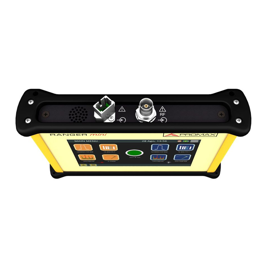
Equipment Details Figure 3. Front View. September 2018 Chapter 2: SETTING UP... - Page 12 Figure 4. Upside View. Chapter 2: SETTING UP September 2018...
-
Page 13: Switching On / Off
Figure 5. Downside View. Switching On / Off Switching On: ► Press the on/off button located on the side of the equipment. The boot screen appears. After the system load, the last screen before shutdown appears. September 2018 Chapter 2: SETTING UP... -
Page 14: Icons Table
Switching Off: ► There are two options : Option 1: Press the ON/OFF button located on the downside of the equipment. A gray screen with a red power off icon will appear. Click on this icon to turn off the equipment or outside the icon to cancel power off. -
Page 15: General Settings
Controls The equipment is operated only using the touch panel. These actions can be done through the touch panel: Menu Selection. Frequency or channel selection or edition. Frequency or channel scroll. Reference level scroll. SPAN selection. Virtual keyboard writing (numerical and alphabetical). General Settings From the Home screen, clicking on the menu icon you access the general... -
Page 16: Firmware Update
Turn OFF the RANGER and insert the flash drive into the USB port. Turn ON the RANGER mini. The update process starts automatically. Wait until finished. Remove the flash drive. Press the ON/OFF button for more than 5 seconds until the equipment turns OFF. -
Page 17: Measurement
3 MEASUREMENT Downstream Spectrum Analyzer Description ► The Downstream function shows on screen the downstream spectrum of the signal received through the input connector in the band between 5 and 2700 MHz. This function shows signals in the frequency band so any problem can be detected easily. - Page 18 Downstream Screen Description ► Figure 7. Downstream Spectrum Selected channel. When pressing on it deploys a list of available channels. Frequency selected. When pressing on it pops up a virtual numeric keypad to edit frequency. DOCSIS Bonding Group selected and carrier. According to signal type: •Digital signal: Power for channel bandwidth or frequency.
- Page 19 DOCSIS BONDING GROUP Screen Description ► Figure 8. DOCSIS Bonding Group Selected channel. Selected channel should belong to a DBG. Channel plan for the channel selected. Channel bandwidth power. DOCSIS Bonding Group selected. When pressing on, it deploys a list of available DBGs.
- Page 20 Options Menu ► There are some options at the bottom of the screen: : Screenshot. : Back to home screen. DBG / DOWNSTREAM: It switches between the DOCSIS BONDING GROUP screen that shows DBG carriers or the Downstream spectrum signal screen. DEMOD: Access to Demodulator (refer to "Demodulator "...
-
Page 21: Upstream
Upstream Description ► The Upstream function shows the upstream spectrum in the band between 5 and 205 MHz allowing to detect impulse noise. User can adjust span and reference level for the frequency or channel tuned. Operation ► Connect signal to the input through F/F or F/BNC adapter. From the main screen press on the UPSTREAM icon. - Page 22 Level for the selected frequency. Full band RF cable power. Marker in the selected frequency. Arrows to change reference level. Span lower frequency. Arrows to increase / decrease span. Current span. Bandwidth resolution. Span upper frequency. Options Menu ► There are some options at the bottom of the screen: : Screenshot.
-
Page 23: Scan
Scan Description ► The SCAN function shows on screen signal level in graphic bar format for each one of the active channels in the selected channel plan. Operation ► Connect signal to the input through F/F or F/BNC adapter. From the main screen press on the SCAN/TILT icon. SCAN function opens. - Page 24 Frequency for the channel selected. DOCSIS Bonding Group selected and carrier (if any). According to signal type: •Digital signal: Power for channel bandwidth or frequency. •Analogue signal: Level for channel or frequency selected. Carrier/Noise ratio of the channel. Full band RF cable power. Marker for selected channel / frequency.
-
Page 25: Tilt
Settings Menu ► Click on the MENU icon at the upper right corner to access the Settings menu. The SCAN function has these options: Edit channel plan: It allows you to edit a channel plan and DBG (refer to "Edit Channel Plan" chapter). Units: It allows you to select a mesurement unit for power (dBuV, dBmV, dBm). - Page 26 Operation ► Connect signal to the input through F/F or F/BNC adapter. From the main screen press on the SCAN/TILT icon. Press on TILT option at the bottom of the screen. TILT function opens. Press on the lower right corner to switch between Upstream and Downstream band.
-
Page 27: Voltmeter
Arrows to change reference level. Bar graph showing signal level for each pilot signal and TILT. Options Menu ► There are some options at the bottom of the screen: : Screeenshot. DATALOGGER: It creates a datalogger with measurement data. : Back to home screen. SCAN: Access the SCAN function. - Page 28 Screen Description ► Figure 12. RF-PWR: Full bandwidth power Vin DC: DC input voltage. Vin AC: AC input voltage and frequency. Iout: Current out. Voltage supply for the LNB: •ON Voltage: Check the box to enable voltage supply. •13 Volts / 18 Volts: Check the box to select between polarization (vertical=13 V;...
-
Page 29: Digital Signal Demodulator
Settings Menu ► Click on the MENU icon at the upper right corner to access the Settings menu. The VOLTMETER function has these options: Units: It allows you to select measurement unit for power (dBuV, dBmV, dBm). Digital Signal Demodulator Description ►... - Page 30 Screen Description ► Figure 13. Demodulated Signal Data. MER for tuned channel. pre-BER (BER before correction). post-BER (BER after correction). Transmission standard. Press to switch. FFT Mode. Press on “i” box to obtain more info. Constellation Diagram (I-Q diagram). Options Menu ►...
-
Page 31: Analog Signal Demodulator
Analog Signal Demodulator Description ► The equipment can measure video carrier signal level, Video/Audio and C/N ratio, HUM and intermodulation products from an analogue signal. This is all shown alongside the screen together with the spectrum analyzer graphic. The HUM is buzz at low frequency modulation that affects video analogue carriers, producing a distinctive hum. - Page 32 Screen Description ► Figure 14. Analogue Video Carrier / HUM. Video c.LVL: Level of video carrier. Audio c.LVL: Level of audio carrier. V/A: Video/Audio ratio. C/N: Carrier/Noise ratio. HUM: Audio carrier. CTB/CSO: Intermodulation product measurement. Press to enable/ disable. Audio OFF/ON: It enables / disables audio and to set audio level. Chapter 3: MEASUREMENT September 2018...
-
Page 33: Tools
4 TOOLS Edit Channel Plan Description ► Channel plan editor allows to edit and create channel plans, and also to edit DBG (Docsis Bonding Group) channels. Operation ► Channel plan editor is available for tools DOWNSTREAM and SCAN . From the tool screen access settings menu by pressing on Press on "Edit Channel Plan"... - Page 34 Screen Description ► Figure 15. Channel plan selected. Press on this box to select another channel plan. Go to: Press on this box to switch between CH (channel) and FR (frequency) and to select a channel or frequency. Channel table. Press on a paremeter to edit o switch among options. Parameters on channel table are: Active: To enable or disable channels.
- Page 35 Options Menu ► There are some options at the bottom of the screen: EDIT DBG: Opens the DBG editor screen (see next section). : Back to main screen. Settings Menu ► Click on the MENU icon at the upper right corner to access the Settings menu.
- Page 36 EDIT DOCSIS BONDING GROUP Screen Description ► Figure 16. Edit DOCSIS Bonding Group: Press on the box below to select a DBG to edit. Add channel: Press on the box next to “Add channel” to select one channel. Then press on ADD to add it to DBG. Remove channel: Press on one channel in the box to select it and then press on REMOVE to remove it from DBG.
- Page 37 Create a Channel Plan from an existing one ► Figure 17. September 2018 Chapter 4: TOOLS...
- Page 38 Figure 18. Press on box "Model" to select a channel plan as a model to create a new one. Press on box "Name" to give a name to the new channel plan. Press "OK" to create a new channel plan or "Cancel" to exit. At the next screen, press on "Add Channel", "Remove Channel"...
- Page 39 Create automatically a channel plan from HFC network ► Figure 19. September 2018 Chapter 4: TOOLS...
- Page 40 Figure 20. Connect to the HFC network. Press on box “Model” to select a channel plan as a model to create a new one. Press on “Start measuring”. When finish press on "Name" box to edit the channel plan name. Press on "Save channel plan"...
-
Page 41: Screenshot
Create a new Channel Plan from scratch ► Figure 21. Press on box "Name" to give a name to the new channel plan. At the next screen, press on “Add Channel”, “Remove Channel” to edit channel plan. When finish, press on “Save channel plan” to save changes or “Cancel”... - Page 42 Operation ► Figure 22. Screenshot is available almost for all functions. To take a screenshot press on photo camera icon at the lower left corner. It pops up a window with a screenshot miniature and some options: “Save and close”, “Save and go to gallery” and “Cancel”. Press your option. To access the photo gallery with all the screenshots, from home screen press on icon at the lower left corner.
-
Page 43: Datalogger - Test & Go
To remove a single screenshot, see the screenshot fullscreen, press on option menu and then on “Remove” and confirm. Datalogger - Test & Go Description ► Datalogger function can made and save automatically several measurements depending on the selected function, including signal level and channel power, carrier/noise, BER and MER for all channels in a specific channel band. - Page 44 A window opens with several setting options. You can edit boxes (name, location, threshold...) when pressing on it. Check the box to select measurements and press on “Start Measuring” or “Cancel”. It starts datalogger. After finish, press on "Save and close", "Save and go to datalogger" or "Cancel".
-
Page 45: Specifications
5 SPECIFICATIONS Spectrum Analyzer ►Frequency Parameter Value Additional Data Tuning Range From 5 to 2700 MHz Tuning Mode By frequency or by channel Bandwidth resolution 230 kHz, 2 MHz Frequency Tuning Resolution 10 kHz Accuracy 20 ppm Sweep time 600 ms full band ►Amplitude Parameter Value... - Page 46 Parameter Value Additional Data Lock range -20 dBmV to 60 dBmV ►ANALOG Spectrum Analyzer Parameter Value Additional Data Tuning Range From 10 to 2700 MHz Video Carrier Signal Level From –45 dBmV to 60 dBmV Audio Carrier signal level, A/V 0- 30 dB (for PAL, SECAM or NTSC standard) 48 dB for input level >...
- Page 47 Scan ►Frequency Parameter Value Additional Data Tuning Range Full frequency band occupied by selected Channel plan Tuning Mode by channel Bandwidth resolution 230 kHz ►Amplitude Parameter Value Additional Data Dynamic range -50 dBmV to 60 dBmV Screen range: 50 dB Max Input level: 70 dBmV Resolution:...
- Page 48 ►Channel Demodulation Parameter Value Additional Data Audio Carrier signal level, A/V 0- 30 dB (for PAL, SECAM or NTSC standard) 48 dB for input level > 10 dBmV HUM (over audio carrier) 1-15%, 1% accuracy CTB/CSO 60 dB dynamic range. (In channel ±...
- Page 49 Parameter Value Additional Data Bandwidth resolution 230 kHz Tuning resolution 10 kHz Dynamic range -50 dBmV to 60 dBmV Screen range 50 dB Max Input level 70 dBmV Resolution 0.1 dB Measurements Level of four selected frequencies ±0 to 30 dB/ MHz (Tilt) between two selected pilots Resolution 0.1 dB...
- Page 50 General Specifications ►Inputs and Outputs Parameter Value Additional Data Interchangeable F, BNC, IEC Optical Available USB type A female Ethernet Available Available Touch Monitor Display Available ►Mechanical Features Parameter Value Additional Data Dimensions 177 x 117 x 30 mm Weight 0.7 kg ►Power Supply Parameter...
-
Page 51: Maintenance
6 MAINTENANCE Instructions for Returning by Mail Instruments returned for repair or calibration, either within or out of the warranty period, should be sent with the following information: Name of the Company, name of the contact person, address, telephone number, receipt (in the case of coverage under warranty) and a description of the problem or the service required. - Page 52 Cleaning the Plastic Case ► The equipment has to be disconnected before cleaning the case. The case must be cleaned with a solution of neutral soap and water, using a soft cloth dampened with this solution. Before use, the equipment has to be completely dry. Never clean with abrasive soaps, chlorinated solvents or aromatic hydrocarbons.
- Page 53 PROMAX ELECTRONICA, S.L.
Need help?
Do you have a question about the RANGER mini and is the answer not in the manual?
Questions and answers