Table of Contents
Advertisement
Quick Links
Download this manual
See also:
User Manual
Advertisement
Table of Contents

Related Manuals for Promax CABLE RANGER


Summary of Contents for Promax CABLE RANGER
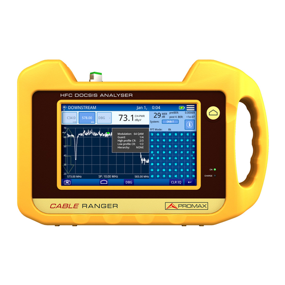
- Page 1 CABLE RANGER FIBER-COAXIAL DOCSIS ANALYZER -0 MI2125 -...
- Page 2 SAFETY NOTES Read the user’s manual before using the equipment, mainly "SAFETY RULES" paragraph. The symbol on the equipment means "SEE USER’S MANUAL". In this manual may also appear as a Caution or Warning symbol. WARNING AND CAUTION statements may appear in this manual to avoid injury hazard or damage to this product or other property.
- Page 3 SAFETY RULES The safety could not be assured if the instructions for use are not closely followed. Use this equipment connected only to systems with their negative of measurement connected to ground potential. The AL-103 external DC charger is a Class I equipment, for safety reasons plug it to a supply line with the corresponding ground terminal.
- Page 4 Symbols related to safety: Descriptive Examples of Over-Voltage Categories Cat I Low voltage installations isolated from the mains. Cat II Portable domestic installations. Cat III Fixed domestic installations. Cat IV Industrial installations. CAUTION: The battery used can present danger of fire or chemical burn if it is severely mistreat.
-
Page 6: Table Of Contents
TABLE OF CONTENTS 1 INTRODUCTION ..................1-1 1.1 Description ..................1-1 2 SETTING UP ....................2-1 2.1 Package Content ................2-1 2.2 Power ................... 2-1 2.2.1 First charge................2-1 2.2.2 Charging the battery ..............2-2 2.2.3 Charge/discharge times ............... 2-3 2.2.4 Usage Tips ................. 2-3 2.3 Equipment Details ................ - Page 7 5 SPECIFICATIONS ..................5-1 5.1 Spectrum Analyzer ................. 5-1 5.2 Scan ..................... 5-2 5.3 Tilt ....................5-4 5.4 DOCSIS Analyzer................5-4 5.5 Upstream Generator ............... 5-6 5.6 External Cable Modem Upstream Spectrum Analyzer ......5-6 5.7 Input Voltage and RF Power Meter ............ 5-7 5.8 Optical Measurement ..............
-
Page 8: Introduction
FIBER-COAXIAL DOCSIS ANALYZER CABLE RANGER 1 INTRODUCTION Description RANGER is the latest introduction in our CATV analyzer product CABLE range. It is an hybrid analyzer (for both fiber optics and coaxial cable) for the installation, configuration and maintenance of interactive video and data services at high speed over TV networks based on the DOCSIS standard. - Page 9 In addition, the instrument provides Ethernet, USB and mini-USB port slots to connect to external devices, to download data and to update firmware. Here are some of the most important functions in the CABLE RANGER. Spectrum Analyzer, Scan, TILT and DOCSIS Analyzer functions are performed through coaxial input and are also available for optical fiber thanks to the optical- electric converter (with the exception of Cable Modem emulation).
-
Page 10: Setting Up
2 SETTING UP Package Content Check that your package contains the following elements: RANGER. Analyser. CABLE External DC charger. Power cord for external DC charger Car lighter charger. "F" Adapters • "F" / H - BNC / H Adapter. (2 u.). •... -
Page 11: Charging The Battery
2.2.2 Charging the battery Connect the DC power adapter to the equipment through the power connector on the left side panel (see figure 3). Figure 2. Then connect the DC power adapter to the mains via the mains cord. Ensure that your mains voltage is compatible with the adapter voltage. -
Page 12: Charge/Discharge Times
Usage Tips The battery is losing storage capacity as you go through its life. Contact your PROMAX distributor when necessary to replace the battery. To prolong battery life the user should follow these tips: In case of providing a long inactivity period of the equipment it is advisable to make every 3 months a charge / discharge cycle and a subsequent partial charge (40% aprox.). -
Page 13: Equipment Details
Equipment Details Front View Figure 3. September 2017... - Page 14 Side view Figure 4. Top view Figure 5. September 2017...
-
Page 15: Switching On/Off The Equipment
Switching On/Off the equipment Switching On: ► Press the on/off button located on the side of the equipment. The boot screen appears. After the system load, the last screen before shutdown appears. Switching Off: ► There are two options: Option 1: Press the on/off button* located on the side of the equipment. -
Page 16: Icons Table
Icons table Icons on the screen provide useful information to the user. Figure 6. September 2017... -
Page 17: Controls
Controls The equipment can be fully operated using the touch panel. These actions can be done through the touch panel: Menu Selection. Frequency or channel selection. Frequency or channel scroll. Reference level scroll. SPAN selection. Virtual keyboard writing (numerical and alphabetical). General Settings From the Home screen, clicking on the menu icon you Access General... -
Page 18: Firmware Update
Firmware Update Keep your device up to date for the latest improvements and features. Follow us on social networks (twitter, Facebook, linkedin, Google+) to get information about updates and latest news: Use a USB flash drive in FAT32 format. Click here to download file with the latest firmware available. -
Page 20: Measures
3 MEASURES Spectrum Analyzer (cable & FO) Description ► The SPECTRUM ANALYZER funtion shows on screen the spectrum of the signal received through the input connector. This function shows signals in frequency band so user can detect any problem and also measure level and demodulate signal. User can select span and reference level by selecting a frequency or channel. - Page 21 Screen Description ► Figure 7. Arrows to increase / decrease value of the selected parameter (channel or frequency). When a parameter is selected its background color is stronger. Selected channel. When pressing on it deploys a list of available channels. Selected channel plan.
- Page 22 Bandwidth resolution. Selected marker for channel / frequency. Options Menu ► There are some options at the bottom of the screen: : Screenshot. DEMOD: Demodulator (refer to "Demodulator " chapter). Settings ► Click on the MENU icon at the upper right corner to access the Settings menu.
-
Page 23: Scan (Cable & Fo)
Scan (cable & FO) Description ► The SCAN function shows on screen signal level in graphic bar format for each one of the active channels in the selected channel plan. Operation ► Connect signal to the input connector: Cable: universal connector for F/F or F/BNC adapter. Fiber Optics: SC-APC connector. - Page 24 Selected channel. When pressing on it deploys a list of available channels. Selected channel plan. When pressing on it deploys a list of available channel plans Frequency selected. When pressing on it pops up a virtual numeric keypad to edit frequency. It shows if the selected channel is digital (D) or analogue (A).
- Page 25 Settings Menu ► MENU icon at the upper right corner to access the Settings menu. Click on the The SCAN function has these options: Edit channel plan: It allows you to edit a channel plan and DBG (refer to "Edit Channel Plan" chapter). Units: It allows you to select a mesurement unit for power (dBuV, dBmV, dBm).
-
Page 26: Tilt (Cable & Fo)
Tilt (cable & FO) Description ► The TILT function is a test to measure tilt in order to equalize the line. TILT is the difference in amplitudes between the minimum and maximum frequency that the system can compensate. The TILT function displays on-screen, graphically and numerically, the difference in level between any four frequencies previously defined as pilots. - Page 27 Screen Description ► Figure 9. P1/P4: End pilot signal. It shows pilot signal frequency and power. P2/P3: Intermediate pilot signals. It shows pilot signal frequency and power. Press on frequency to change its value. TILT: Inclination rate in dB per MHz. Power difference between P1 and P4.
-
Page 28: Docsis Analyzer (Cable & Fo)
Settings Menu ► Click on the MENU icon at the upper right corner to access the Settings menu. The TILT function has these options: Units: It allows you to select a measurement unit for power (dBuV, dBmV, dBm). DOCSIS Analyzer (cable & FO) Introduction ►... -
Page 29: Docsis Downstream Spectrum Analyzer
Select DOCSIS ANALYZER function according to input signal (cable or fiber). Press function on the left side of the screen for FIBER OPTICS or on the right side for CABLE. DOCSIS DOWNSTREAM SPECTRUM ANALYZER function opens. To analyze a DOCSIS BONDING GROUP, select a DBG and then press on DBG. - Page 30 Arrows to increase / decrease value of the selected parameter (channel or frequency). When a parameter is selected its background color is stronger. Selected channel. When pressing on it deploys a list of available channels. Selected channel plan. When pressing on it deploys a list of available channel plans.
- Page 31 Settings Menu ► Click on the MENU icon at the upper right corner to access the Settings menu. The DOCSIS DOWNSTREAM SPECTRUM ANALYZER function has these options: Edit channel plan: It allows you to edit a channel plan and DBG (refer to "Edit Channel Plan"...
-
Page 32: Docsis Bonding Group
3.4.2 DOCSIS BONDING GROUP Description ► DBG function shows power for each channel and carrier belonging to DOCSIS BONDING GROUP. Screen Description ► Figure 11. Power for each DBG carrier. Arrow on the bar indicates carrier selected. Constellation Diagram. Options Menu ►... -
Page 33: Ranging (Only For Cable)
Settings ► Click on the MENU icon at the upper right corner to access the Settings menu. The DOCSIS BONDING GROUP function has these options: Edit channel plan: It allows you to edit a channel plan and DBG (refer to "Edit Channel Plan" chapter). CM Information: It shows information... - Page 34 Downstream and Upstream channel ranging. Downstream System: Transmission standard SR: Symbol Rate. MOD: Modulation. MER: Modulation Error Ratio. PreBER: Error ratio before correction. PostBER: Error ratio after correction. Interleaver: Improvement of error correction performance. Offset: Offset for tuning frequency. Upstream UCD: Upstream Channel Descriptor.
-
Page 35: Docsis Registering
3.4.4 DOCSIS REGISTERING Description ► It is necessary to register your equipment in the CMTS network to access functions check VoIP, IPTV Browser. When registering, Downstream and Upstream features are shown on screen. Screen Description ► Figure 13. Downstream CH: Channel. F: Frecuency. - Page 36 Options Menu ► There are some options at the bottom of the screen: : Screenshot. DBG: It opens DOCSIS BONDING GROUP function (see previous section). Test IP: It opens IP TEST (VoIP/IPTV)function (see next section). BROWSER: It opens DOCSIS BROWSER function. Setting Menu ►...
-
Page 37: Iptv
3.4.5 IPTV Description ► The IPTV test function performs an analysis of quality parameters for this type of service. The optimization of these parameters guarantees the best quality of service. In addition, knowledge of network conditions is important to install and fix other problems. ►... - Page 38 Options Menu ► There are some options at the bottom of the screen: : Screenshot. LOGGER: It creates a datalogger with measurement data. REGISTER: It returns to the DOCSIS REGISTERING function (see previous section). VoIP: VoIP: IP TEST: VoIP function opens (see next section). Settings Menu ►...
-
Page 39: Voip
3.4.6 VoIP Description ► The VoIP function performs a comprehensive analysis of the network based on parameters defined by UGS, which guarantees the best quality of service. It analyzes several parameters that can affect quality of communication such as latency, jitter, lost packets, MOS and R. value. Screen Description ►... - Page 40 Options Menu ► There are some options at the bottom of the screen: : Screenshot. LOGGER: It creates a datalogger with measurement data. REGISTER: It returns to the DOCSIS REGISTERING function (see previous section). IPTV: IPTV function opens (see previous section). Settings Menu ►...
-
Page 41: Docsis Browser
3.4.7 DOCSIS BROWSER Description ► DOCSIS BROWSER allows you to check web browsing.. Screen Description ► Figure 16. : Previous page. : Next page. : Reload page. URL bar: enter address and press Go. Keyboard: It shows virtual keyboard to enter URL. User / Pass : Password and user to enter CM administrator page. -
Page 42: Ext. Cm / Upstream
Options Menu ► There are some options at the bottom of the screen: : Screenshot. REGISTERING: It returns to the DOCSIS REGISTERING function (see previous section). EXT. CM / UPSTREAM Description ► The External CM / Upstream Spectrum function extracts a sample of the upstream signal and displays its spectrum on the screen. - Page 43 Screen description ► Figure 17. Arrows to increase / decrease value of the selected parameter (channel or frequency). When a parameter is selected its background color is stronger. Frequency selected. When pressing on it pops up a virtual numeric keypad to edit frequency. Power level at selected frequency.
-
Page 44: Upstream Test (Cable)
Settings Menu ► Click on the MENU icon at the upper right corner to access the Settings menu. The EXT. CM / UPSTREAM function has these options: Trace: It allows you to select holding type of trace (maximal, minimum). Frequency step: It allows you to select frequency step (0.25 MHz, 1 MHz, 8 MHz, other value). - Page 45 Screen description ► Figure 18. Parameters to set UPSTREAM signal Frequency mode: Select between Sweep or Fix. Frequency start: Select start frequency (only for Sweep mode). Frecuency stop: Select stop frequency (only for Sweep mode). Frequency: Select frequency (only for Fix mode). Power: Select power level for signal.
-
Page 46: Ac / Dc Input Voltage
AC / DC Input Voltage Description ► The AC / DC input voltage function automatically identifies the voltage type (DC or AC) at the input and the frequency in case of alternating voltage. Operation ► Connect signal to the input connector: Cable: universal connector for F/F or F/BNC adapter.. -
Page 47: Optical Power Meter
Optical Power Meter Description ► The OPTICAL POWER METER function measures power for each wavelength thanks to selective filters that only let pass the signal corresponding to the wavelength selected. Operation ► Connect signal to the input connector: Cable: universal connector for F/F or F/BNC adapter. Fiber Optics: SC-APC connector. - Page 48 RF-PWER: Graphical bar and value of RF power. Relative Power: Graphical bar and value of power signal loses. It is equal to: Relative Power = Reference value - Attenuation. Options Menu ► There are some options at the bottom of the screen: : Screenshot.
-
Page 50: Tools
4 TOOLS Edit Channel Plan Description ► Channel plan editor allows to edit and create channel plans, and also to edit DBG (Docsis Bonding Group) channels. Operation ► Channel plan editor is available in these functions: SPECTRUM ANALYZER, SCAN and DOCSIS ANALYZER. Select channel plan on main screen. - Page 51 Screen Description ► Figure 21. Channel plan selected. Press on this box to select another channel plan. Go to: Pulse sobre esta casilla para cambiar entre CH (canal) y FR (frecuencia) y seleccionar el canal o frecuencia que desee seleccionar. Channel table.
- Page 52 Options Menu ► There are some options at the bottom of the screen: Edit DBG: Opens the DBG editor screen (see next section). : Back to main screen. Settings Menu ► Click on the MENU icon at the upper right corner to access the Settings menu.
- Page 53 EDIT DOCSIS BONDING GROUP Screen Description ► Figure 22. Edit Docsis Bonding Group: Press on the box to select DBG to edit. Add channel to DBG: Press on arrows or on the box to select one channel and then press on ADD to add to DBG. Remove channel to DBG: Press on arrows or on the box to select one channel and then press on REMOVE to remove from DBG.
- Page 54 Figure 24. Press on box "Model" to select a channel plan as a model to create a new one. Press on box "Name" to give a name to the new channel plan. Press "OK" to create a new channel plan or "Cancel" to exit. At the next screen, press on "Add Channel", "Remove Channel"...
- Page 55 Figure 26. Connect to the HFC network. Press on box "Model" to select a channel plan as a model to create a new one. Press on "Start measuring". When finish press on "Name" box to edit the channel plan name. Press on "Save channel plan"...
-
Page 56: Demodulator
Demodulator Description ► Demodulator are probably the most important measurements technicians can do to assess digital QAM channel quality. Constellation diagram is a simple and graphical way to identify signal impairments which impact MER and ultimately BER. An ideal QAM channel for example will be represented by a set (constellation) of very sharp dots. -
Page 57: Analog Video Carrier / Hum
pre-BER (BER before correction). post-VER (BER after correction). Transmission standard. Press to switch. Modulation type. Press to switch. Signal status LOCKED / UNLOCKED Symbol rate. Press to switch. Constellation Diagram (I-Q diagram). Options Menu ► CLR IQ: It clears constellation. Back to previous screen. - Page 58 Screen Description ► Figure 29. Analogue Video Carrier / HUM. Video c.LVL: Level of video carrier. Audio c.LVL: Level of audio carrier. V/A: Video/Audio ratio. C/N: Carrier/Noise ratio. HUM: Audio carrier. CTB/CSO: Intermodulation product measure. Audio OFF/ON: It enables / disables audio and level. September 2017...
-
Page 59: Screenshot
Screenshot Description ► It saves a screenshot of current screen that can be downloaded to a USB flashdrive. Operation ► Figure 30. Screenshot is available in these functions: SPECTRUM ANALYZER, SCAN, TILT, DOCSIS ANALYZER, EXT. CM / UPSTREAM, INPUT VOLTAGE To take a screenshot press on photo camera icon at the lower left corner. -
Page 60: Datalogger
Datalogger Description ► Datalogger function can logger automatically several measures depending on the selected function, including signal level and channel power, carrier/noise, BER and MER for all channels in a specific channel band. Operation ► Figure 31. Datalogger is available for these functions: SCAN, TILT, DOCSIS ANALYZER and OPTICAL POWER METER. -
Page 62: Specifications
5 SPECIFICATIONS Spectrum Analyzer Frequency ► Parameter Value Additional data Tuning Range From 5 to 1700 MHz 1200MHz (DOCSIS) 1700 MHz (DOCSIS 3.1) Tuning Mode By Frequency or by channel Bandwidth resolution 230 kHz, 2 MHz Frequency step 10 KHz Accuracy 20 ppm Sweep time... -
Page 63: Scan
Measurements: Analog Channel demodulation ► Parameter Value Additional data Video Carrier signal level From -45 dBmV to 60 dBmV Channel demodulation ► Parameter Value Additional data Audio Carrier signal level, 0- 30 dB (for PAL, SECAM or NTSC standard) 48 dB for input level > 10 dBmV HUM (over audio carrier) 1-15%, 1% accuracy CTB/CSO... -
Page 64: Configuration Menu
Measurements: DIGITAL Channel ► Parameter Value Additional data Power From –40 dBmV to 60 dBmV Power measurement in the channel bandwidth by integration method at the marker. Represented by vertical blue bars Channel Demodulation ► Parameter Value Additional data QAM Systems compatibility DVB-C, ITUJ83 Annex B and C 1000-7000 ksym/s From 24 dB to 43 dB for QAM... -
Page 65: Tilt
Tilt Downstream ► Parameter Value Additional data Frequency Four selectable tuning frequencies (pilots) from 45 MHz to 1700 MHz Tuning resolution 10 kHz Bandwidth resolution 230 kHz Dynamic range -50 dBmV to 60 dBmV Screen range 50 dB Max Input level 70 dBmV Resolution 0.1 dB... - Page 66 Amplitude ► Parameter Value Additional data Dynamic range -50 dBmV to 60 dBmV Screen range 50 dB Max Input level 70 dBmV Resolution 0.1 dB Accuracy ±2 dB Input impedance 75 Ω Units dBmV, dBμV, dBm Measurements: Frequency tunning mode ►...
-
Page 67: Upstream Generator
Configuration Menu ► Parameter Value Additional data Channel Plan Stantard TV Channel plans CCIR,EIA,HRC,IRC,OIRL,FCC up to 10 Customized Channel plan Up to 30 Units dBmV, dBμV, dBm Reference Line From –60 dBmV to 120 dBmV Trace Normal, max hold and min hold Frequency Step From 10 kHz to 100 MHz Top Frequency... -
Page 68: Input Voltage And Rf Power Meter
Amplitude ► Parameter Value Additional data Dynamic Range -50 dBmV to 60 dBmV Screen range 50 dB Max input level 70 dBmV Resolution 0.1 dB Accuracy ± 2 dB Input impedance 75 Ω Units DBmV, dBmV, dBm Configuration ► Parameter Value Additional data Trace... -
Page 69: General Specifications
Optical to RF Converter ► Parameter Value Additional data Optical Band 1100 nm – 1700 nm (Optical band pass filter as especial option) RF Band 45 MHz to 1700 MHz Dynamic range -26 dBm to 0 dBm Operation RF from optics internally redirect TO SPECTRUM ANALYZER, SCAN, TILT and DOWN stream DOCSIS analyzer General specifications... -
Page 70: Maintenance
Operating Environmental Conditions ► Parameter Value Additional data Altitude Up to 2000 m Temperature range From 5 °C to 45 °C Automatic disconnection by excess of temperature Max. Relative humidity up to 31°C; decreasing lineally up to 50 % at 40 °C. NOTE: Equipment specifications are set in these environmental operating conditions. -
Page 71: Cleaning Recommendations
Cleaning Recommendations The equipment consists of a plastic case and a TFT screen. Each element has its specific cleaning treatment. Cleaning the TFT screen The TFT screen surface is VERY DELICATE. It has to be cleaned with a soft fabric cloth (cotton or silk), always making the same move from left to right and from top to bottom, without putting pressure on the screen.
Need help?
Do you have a question about the CABLE RANGER and is the answer not in the manual?
Questions and answers