Table of Contents
Advertisement
Quick Links
9800 Martel Road
Lenoir City, TN 37772
www.ps-engineering.com
PAC45D
Special Mission Audio Controller System with
MultiTalker® and IntelliVOX®
Document P/N 200-045-0100
January 2020
Audio Control System with MultiTalker Technology
High-fidelity Stereo Intercom
System Installation and Operation Manual
FAA - TSO C139a
Patented under one or more of the following;
No. 4,941,187; 5,903,227; 6,160,496 and 6,493,450, 7,391,877
In certified aircraft, warranty is not valid unless this product is installed by an
Authorized PS Engineering dealer.
PS Engineering, Inc. 2020 ©
Copyright Notice
Any reproduction or retransmittal of this publication, or any portion thereof, without the expressed written permission of PS En-
gineering, Inc. is strictly prohibited. For further information, contact the Publications Manager at PS Engineering, Inc., 9800
Martel Road, Lenoir City, TN 37772. Phone (865) 988-9800, email contact@ps-engineering.com.
Advertisement
Table of Contents

Related Manuals for PS Engineering PAC45D


Summary of Contents for PS Engineering PAC45D
- Page 1 Any reproduction or retransmittal of this publication, or any portion thereof, without the expressed written permission of PS En- gineering, Inc. is strictly prohibited. For further information, contact the Publications Manager at PS Engineering, Inc., 9800 Martel Road, Lenoir City, TN 37772. Phone (865) 988-9800, email contact@ps-engineering.com.
-
Page 2: Table Of Contents
ELEPHONE ATELLITE OMMUNICATION INPUT 2.4.10 M ......................... 2-8 USIC NPUT 2.4.11 R (-RXI) ................... 2-8 ECEIVE CTIVITY NDICATOR 2.4.12 C (PAC45D 050-045-0006 HUB45R 050-045-0103 ) ..2-8 OCKPIT PEAKER UTPUT ONLY ............................2-8 DJUSTMENTS 2.5.1 U ....................2-8 NSWITCHED UDIO EVEL 2.5.2 A... - Page 3 ARRANTY ..............................A ACTORY ERVICE Appendix A – PAC45D Installation Drawings ............. A Appendix B – Radio Interconnect Wiring A Appendix C – Intercom Interconnect Wiring .............. A Appendix D – Control Head Interconnect Wiring ............A Appendix E, Unit Connector Wiring Reference ............A J451 C .............................A...
-
Page 4: Introduction
Before installing and/or using this product, please read this manual completely. This will ensure that you will take full advantage of all the advanced features in the PAC45D. 1.1.1 Limitations This article meets the minimum performance and quality control standards required by a tech- nical standard order (TSO). -
Page 5: Equipment Description
Consult PS Engineering for specific LRU part number. EQUIPMENT DESCRIPTION The PAC45D is a state-of-the-art audio isolation amplifier and audio selector that contains an au- tomatic voice activated (VOX) intercom system. It can switch six transceivers (Com 1 - 6) and six receivers (Nav 1, Nav 2, MKR, and three additional inputs that can be individually labeled, for use with ADF, DME, AUX, etc.). -
Page 6: Specifications
Up to 55,000 feet in a non-pressurized area of the cockpit. DIMENSIONS: Height: 1.9 in. (4.8 cm) Width: 5.75 in. (14.6 cm) Depth behind panel (PAC45D): 7.38 in. (18.75 cm) in- cluding connectors UNIT WEIGHT PAC45D -001 2.0 lb. (0.90 kg) HUB45 1.0. -
Page 7: Equipment Supplied
<1% THD @ 100 mW into 150 Mic Freq. Response, 3 dB: 300 Hz - 6000 Hz Stereo Music Freq. Response, 3 dB: 20 Hz – 16 kHz EQUIPMENT SUPPLIED The following units comprise the PAC45D System: Model Description Standard NVIS Compatible Part Number... - Page 8 PS Engineering PAC45 Audio Selector Panel and Intercom System Installation and Operator’s Manual Description PSE Part Number Qty. Manufacturer MFR Part Number 50 Pin Female Conn, Housing 425-050-0967 Harting 09670504701 37 Pin Female Kit Connector 425-037-1757 TE Connectivity 1757820-9 w/Pins...
- Page 9 Deutsch M39029/64-368 EQUIPMENT REQUIRED BUT NOT SUPPLIED Circuit Breakers: 1 ea.; 1 amp PULL TYPE REQUIRED for PAC45D,0.5 A for CTL45s Optional Circuit Breaker: 0.5 ea.; 1 amp PULL TYPE REQUIRED for PAC45D aural alerts Headphone Jacks (Stereo, as Required) Microphone Jacks (as Required) Headphones, 150 ...
-
Page 10: Configurations
Installation and Operator’s Manual Configurations The PAC45D System is comprised of three “building blocks” to facilitate flexibility as well as sim- plicity. The simplest, single audio controller system is a PAC45D where the audio hub is attached to the control head. HUB45 CTL45D... -
Page 11: Section Ii - Installation
2.3 Equipment Installation Procedures 2.3.1 Cooling Requirements Forced air-cooling of the PAC45D is not required. However, the units should be kept away from heat producing sources (i.e. defrost or heater ducts, dropping resistors, heat producing avionics) without adequate cooling air provided. -
Page 12: Audio Controller Connector Assembly
2.3.3 Audio controller Connector Assembly The LRU connectors mate with one 50-pin, one 37-pin, and two 26-pin connectors in the PAC45D. The connectors are a sub-miniature crimp-type, and require the use a hand crimp tool, from table below (or equiv.). -
Page 13: Cable Harness Wiring
PAC45 Audio Selector Panel and Intercom System Installation and Operator’s Manual PS Engineering recommends that Loctite #425 be added to any thumbscrew that is removed and reinstalled. Loctite #425 is added to the thumbscrew threads at the factory. 2.4 Cable Harness Wiring Referring to the appropriate Appendix, assemble a wiring harness as required for the installa- tion. -
Page 14: Power
2.4.2 Power The PAC45D is compatible with 28 Volt DC systems. A one (1) Amp circuit breaker is required for all installations. Power and ground wires should be #22AWG connect power to P451 Pin 17. -
Page 15: Transmit Interlock
The PAC45D system can support six passenger intercom stations, in addition to the pilot and co- pilot. The input to the PAC45D P451 6, 23, 40 can be used as an additional transmit position, or a hand microphone, or as passenger 6, with transmit capability on the selected radio. - Page 16 PS Engineering PAC45 Audio Selector Panel and Intercom System Installation and Operator’s Manual By default, adjustments to the pot change the minimum trip point for the dimmer input to full bright. The pot permits adjustment from 0V to nominal dimmer voltage (28V or 5V depending on configuration).
-
Page 17: Unswitched Inputs
(or the remote ACK P454-9 grounded), or the input level reverts. When power is applied to the alerts and not the PAC45D audio controller, it will play the mes- sage three times or until the remote acknowledge is selected. -
Page 18: Wired Telephone/Satellite Communication Input
Pilot’s PAC45D. 2.4.9 Wired Telephone/Satellite Communication input The PAC45D can accommodate a wired cell phone interface on P454 Pins 17, 26 and 7. Both Bluetooth and wired Telephone and be accommodated, however, only ONE can be active at a time. -
Page 19: Adjustment Pots
Also, ACK can be pressed at any time to exit (if you want to adjust green but not white for example) 2.5.3 Logic Switch Options The PAC45D has several switches accessible through the side of the HUB45 to set specific func- tions 200-045-0100... - Page 20 PS Engineering PAC45 Audio Selector Panel and Intercom System Installation and Operator’s Manual Power must be cycled after selections are completed. 1-3: Alert polarity (ground or voltage trigger) 4-6: Alert type (edge or trigger) 7: Dimmer mode (5VDC or 28VDC) 8: Mic sensitivity (High noise applications) 9: Passenger HRTF enable (MultiTalker®...
- Page 21 PS Engineering PAC45 Audio Selector Panel and Intercom System Installation and Operator’s Manual As shown: Observer Control Head in System 12 11 10 9 8 7 6 5 4 3 2 1 200-045-0100 Page 2-11 January 2020...
-
Page 22: Pac45D Pin Assignments
PS Engineering PAC45 Audio Selector Panel and Intercom System Installation and Operator’s Manual 2.6 PAC45D Pin assignments P451 P452 FUNCTION FUNCTION COM2 KEY UNSWITCHED AUDIO 2 COM1 KEY COM 2 AUDIO HI COM3 KEY COM 1 AUDIO HI COM4 KEY... -
Page 23: Wiring Checkout
NOTE: Serial TX 3 for Mission Observer Control Head 2.7 Wiring Checkout After wiring is complete, verify power is ONLY on pin 16 &17 of J451and airframe ground on pin 34. Failure to do so will cause serious internal damage and void PS Engineering's warranty. 200-045-0100 Page 2-13... -
Page 24: Operational Checkout
2.8 Operational Checkout 2.8.1 Required Test Equipment In order to return an aircraft to service after installation of the PAC45D, the installer must have access to headset(s), and be able to establish 2-way communications on appropriate radios. Equivalent test equipment is acceptable as long as the testing requirements can be met. -
Page 25: Final Inspection
Installation and Operator’s Manual 2.8.3.1 TEL Checkout Pair the PAC45D with a Bluetooth telephone device. Verify that the pilot headset is connected to the cellular telephone system (if installed). The telephone function will allow any person heard by the pilot on the intercom, also heard on the telephone. -
Page 26: Section Iii Operation Scope
Panel/Intercom Systems. Please read it carefully before using the equipment so that you can take full advantage of its capabilities. This section is divided into sections covering the basic operating areas of the PAC45D systems. They are Communications Transceiver Selection, Audio Selector, Intercom, and special func- tions, including the Bluetooth®... -
Page 27: Communications Transmit (Xmt) Selection
The radio is automatically selected to receive incoming radio calls when the XMT is selected. With a PAC45D, you will never transmit on a radio that you are not receiving. The selected audio is indicated by both knob position and the green LED indicator. -
Page 28: Audio Location
3.4.5 Monitor Mode With the toggle switch in the “down” position, the PAC45D is in Monitor Mode. In this mode, the audio from the COM radio that is selected for transmit will mute the other COM audio when it is active. -
Page 29: Speaker Control
PS Engineering PAC45A Audio Selector Panel and Intercom System Installation and Operator’s Manual 3.4.7 Speaker Control (PAC45D 050-045-0002, HUB45R 050-045-0102 only) If equipped, the SPR label will be on the unit below the ICS button. Press and hold the ICS button to toggle the output ON/OFF. When the speaker output is “ON”, all alerts, unswitched inputs and all switched inputs selected by the pilot will be pre- sent. -
Page 30: Push To Talk Intercom (Ptt Ics)
It has no effect on selected radio levels, or music input levels. In the PAC45D, the pilot volume control adjusts the pilot’s intercom volume. The copilot’s knob adjusts the copilot, and any connected passengers. -
Page 31: Intercom Modes
3.6.1 Pairing and unpairing Bluetooth devices The PAC45D can be paired with up to eight individual devices, but will only connect to one at a time. When that number is exceeded, the PAC45D will drop a device to allow the new device to be added. -
Page 32: Bluetooth® Telephone Mode
In CREW mode, the pilot and copilot are connected to the telephone. In ISO intercom mode, when the PAC45D is in the TEL mode, the pilot position is in the "Phone Booth." Only the pilot will hear the telephone, and only he will be heard. -
Page 33: Section Iv - Warranty And Service A
All domestic transportation charges for returning the exchange or repaired unit to the purchaser will be borne by PS Engineering, Inc. The risk of loss or damage to the product is borne by the party making the shipment, unless the purchaser requests a specific method of shipment. -
Page 34: Appendix A - Pac45D Installation Drawings
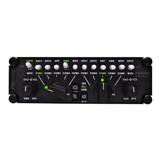
PS Engineering PAC45A Audio Selector Panel and Intercom System Installation and Operator’s Manual Appendix A – PAC45D Installation Drawings Figure 5-1 – PAC45D Rear/Connector View (not to scale) J451: 50-PIN FEMALE ON HARNESS Figure 5-2 – PAC45D Side View Figure 5-3 - PAC45D/CTL45D Front View... - Page 35 PS Engineering PAC45A Audio Selector Panel and Intercom System Installation and Operator’s Manual PAC45D Overall Top View 200-045-0100 Appendix A January 2020...
- Page 36 PS Engineering PAC45A Audio Selector Panel and Intercom System Installation and Operator’s Manual CTL45D Top View 200-045-0100 Appendix A January 2020...
- Page 37 PS Engineering PAC45A Audio Selector Panel and Intercom System Installation and Operator’s Manual HUB45R Top View Figure 5-4 - HUB45R Side View 200-045-0100 Appendix A January 2020...
- Page 38 PS Engineering PAC45A Audio Selector Panel and Intercom System Installation and Operator’s Manual Appendix B – Radio Interconnect Wiring PAC45 Radio Connections P452 P451 Com 1 Audi o Hi Com 1 Lo COM 1 Com 1 Mic Audio Hi Com 1 Mic Key...
-
Page 39: Appendix C - Intercom Interconnect Wiring
PS Engineering PAC45A Audio Selector Panel and Intercom System Installation and Operator’s Manual Appendix C – Intercom Interconnect Wiring P453 P451 P452 P454 Pilot Mic Audio Hi Pilot Mic Lo Pilot Mic PTT PIL PHN (R) Pilot Phones Jack Pilot ICS PTT... -
Page 40: Appendix D - Control Head Interconnect Wiring
PS Engineering PAC45A Audio Selector Panel and Intercom System Installation and Operator’s Manual Appendix D – Control Head Interconnect Wiring PAC45 P 45 5 J4 55 OBSR HUB LRU P455 J4 53 R X- R S422 TX - R X- R S422 TX -... -
Page 41: Appendix E, Unit Connector Wiring Reference
PS Engineering PAC45A Audio Selector Panel and Intercom System Installation and Operator’s Manual Appendix E, Unit Connector Wiring Reference 9.1 J451 Connections P451 PAC45 Connectors, J451 Com 1 Mic Audio Hi Com 1 Mic Key COM 1 Com 1 Mic Low... -
Page 42: J452 Connections
PS Engineering PAC45A Audio Selector Panel and Intercom System Installation and Operator’s Manual 9.2 J452 Connections P452 PAC45 Connector, J452 Com 1 Audio Hi COM 1 Com 1 Lo Com 2 Audio Hi COM 2 Com 2 Audio Low Com 3 Audio Hi... -
Page 43: J453 Connections
PS Engineering PAC45A Audio Selector Panel and Intercom System Installation and Operator’s Manual 9.3 J453 Connections P453 P A C 45 D C o nnec to rs, J45 3 Serial TX- C O N N E C T TO A IR C R A FT P O W E R... -
Page 44: J454 Connections
PS Engineering PAC45A Audio Selector Panel and Intercom System Installation and Operator’s Manual 9.4 J454 Connections J454 Connections with Pilot & Copilot CVR Output (050-045-0005 and 050-045-0101) TEL Audio Hi SAT/COM TEL Audio Low TEL Mic Audio Hi Cockpit PILOT C VR OUT... -
Page 45: Appendix F - Instructions For Faa Form 337 And Continuing Airworthiness
Aircraft equipment list, weights and balance amended. Compass compensation checked. A copy of the operation in- structions, contained in PS Engineering document 202-045-( ), revision ( ), dated ( ), is placed in the aircraft records. All work accomplished listed on Work Order 10.2 Instructions for Continuing Airworthiness, Audio System... -
Page 46: Appendix G - Rtca Do160G Environmental Qualification Form
PAC45A Audio Selector Panel and Intercom System Installation and Operator’s Manual Appendix G – RTCA DO160G Environmental Qualification Form 11.1 Model Number PAC45D Audio Selector Panel/Intercom Remote Hub Part Number: 050-045-( ) FAA TSO Number: C139a, Manufacturer: PS Engineering Incorporated... -
Page 47: Model Number Ctl45, Audio Selector Control Panel
PAC45A Audio Selector Panel and Intercom System Installation and Operator’s Manual 11.2 Model Number CTL45, Audio Selector Control Panel Part Number: 050-045-(02XX, -03XX, -62XX, -63XX ) FAA TSO Number: C139a Manufacturer: PS Engineering Incorporated 9800 Martel Road Lenoir City TN 37772 Conditions Section...
Need help?
Do you have a question about the PAC45D and is the answer not in the manual?
Questions and answers