Table of Contents
Advertisement
Quick Links
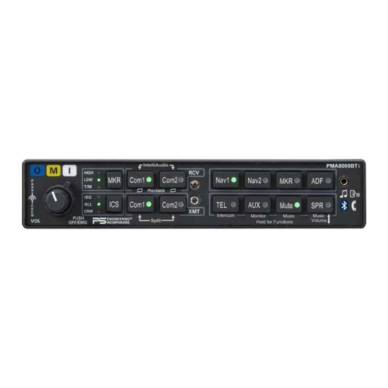
Audio Selector Panel with Marker Beacon Receiver
Audio Selector Panel with Marker Beacon Receiver
Audio Selector Panel with Marker Beacon Receiver
Patented under one or more of the following;
Patented under one or more of the following;
Patented under one or more of the following;
No. 4,941,187; 5,903,227; 6,160,496 and 6,493,450
No. 4,941,187; 5,903,227; 6,160,496 and 6,493,450
No. 4,941,187; 5,903,227; 6,160,496 and 6,493,450
In certified aircraft, warranty is not valid unless this product is installed by an
In certified aircraft, warranty is not valid unless this product is installed by an
In certified aircraft, warranty is not valid unless this product is installed by an
Any reproduction or retransmittal of this publication, or any portion thereof, without the expressed written permission of PS
Any reproduction or retransmittal of this publication, or any portion thereof, without the expressed written permission of PS
Any reproduction or retransmittal of this publication, or any portion thereof, without the expressed written permission of PS
Engineering, Inc. is strictly prohibited. For further information contact the Publications Manager at PS Engineering, Inc., 9800
Engineering, Inc. is strictly prohibited. For further information contact the Publications Manager at PS Engineering, Inc., 9800
Engineering, Inc. is strictly prohibited. For further information contact the Publications Manager at PS Engineering, Inc., 9800
Martel Road, Lenoir City, TN 37772. Phone (865) 988-9800, email contact@ps-engineering.com.
Martel Road, Lenoir City, TN 37772. Phone (865) 988-9800, email contact@ps-engineering.com.
Martel Road, Lenoir City, TN 37772. Phone (865) 988-9800, email contact@ps-engineering.com.
9800 Martel Road
9800 Martel Road
9800 Martel Road
Lenoir City, TN 37772
Lenoir City, TN 37772
Lenoir City, TN 37772
www.ps-engineering.com
www.ps-engineering.com
www.ps-engineering.com
P
P
P
M
M
M
A
A
A
8
8
8
P
P
P
M
M
M
A
A
A
8
8
8
Document P/N 200-890-1722
Document P/N 200-890-1722
Document P/N 200-890-1722
Revision 1, March 2016
Revision 1, March 2016
Revision 1, March 2016
High-fidelity Stereo Intercom
High-fidelity Stereo Intercom
High-fidelity Stereo Intercom
System Installation and Operation Manual
System Installation and Operation Manual
System Installation and Operation Manual
FAA- TSO C50c, C35d
FAA- TSO C50c, C35d
FAA- TSO C50c, C35d
EASA ETSO C50c, 2C35d
EASA ETSO C50c, 2C35d
EASA ETSO C50c, 2C35d
Authorized PS Engineering dealer.
Authorized PS Engineering dealer.
Authorized PS Engineering dealer.
PS Engineering, Inc. 2016 ©
PS Engineering, Inc. 2016 ©
PS Engineering, Inc. 2016 ©
Copyright Notice
Copyright Notice
Copyright Notice
0
0
0
0
0
0
0
0
0
B
B
B
T
T
T
0
0
0
0
0
0
0
0
0
B
B
B
T
T
T
i
i
i
i
i
i
Advertisement
Table of Contents

Related Manuals for PS Engineering PMA8000BTi


Summary of Contents for PS Engineering PMA8000BTi
- Page 1 Any reproduction or retransmittal of this publication, or any portion thereof, without the expressed written permission of PS Engineering, Inc. is strictly prohibited. For further information contact the Publications Manager at PS Engineering, Inc., 9800 Engineering, Inc. is strictly prohibited. For further information contact the Publications Manager at PS Engineering, Inc., 9800 Engineering, Inc.
-
Page 2: Table Of Contents
Table of Contents Section I – GENERAL INFORMATION..............1-1 INTRODUCTION..........................1-1 SCOPE .............................. 1-1 EQUIPMENT DESCRIPTION....................... 1-1 APPROVAL BASIS ......................... 1-2 SPECIFICATIONS.......................... 1-2 EQUIPMENT SUPPLIED....................... 1-4 EQUIPMENT REQUIRED BUT NOT SUPPLIED ..............1-4 OPTIONAL ITEMS......................... 1-4 LICENSE REQUIREMENTS......................1-4 Section II - INSTALLATION GENERAL INFORMATION...................... - Page 3 PS Engineering PMA8000BTi IntelliAudio Audio Selector Panel and Intercom System Installation and Operator’s Manual 2.12.1 R ..................2-12 EQUIRED QUIPMENT 2.12.2 A ...................... 2-12 UDIO ANEL 2.12.3 M ....................2-13 ARKER HECKOUT 2.12.4 TEL C ......................2-13 HECKOUT 2.12.5 I ................
-
Page 4: Section I - General Information
(Com 1, Com 2) and six receivers (Nav 1, Nav 2, ADF, DME, MKR and AUX). A full duplex TEL mode allows the PMA8000BTi to act as an audio interface between aircraft headphone and microphones and specific aircraft approved (FAA/FCC) cellular telephone equipment, through the front mounted jack. -
Page 5: Approval Basis
PMA8000BTi IntelliAudio Audio Selector Panel and Intercom System Installation and Operator’s Manual A 3-light, 75 MHz Marker Beacon receiver is integrated in the PMA8000BTi. This provides the necessary Marker Beacon lights and audio indications necessary for that portion of an Instrument Landing System (ILS) approach. - Page 6 PS Engineering PMA8000BTi IntelliAudio Audio Selector Panel and Intercom System Installation and Operator’s Manual Audio Selector Specifications Audio selector panel input impedance: 510 Input Isolation: -60 dB (min.) Speaker Muting: -60 dB (min.) Speaker Output (into 4 ) with no clipping 3 Watts (min.)
-
Page 7: Equipment Supplied
PS Engineering PMA8000BTi IntelliAudio Audio Selector Panel and Intercom System Installation and Operator’s Manual EQUIPMENT SUPPLIED 1 ea. of the following units: Model Description Part Number PMA8000BTi PMA8000BT Audio Panel with IntelliAudio, Marker, Stereo 050-890-0712 Intercom, and Bluetooth connectivity PMA8000BT Installation Kit: 250-890-0000... -
Page 8: Section Ii - Installation
Section 1.6 (B). If any claim is to be made, save the shipping material and contact the freight carrier. Do NOT return units damaged in shipping to PS Engineering. If the unit or ac- cessories show any sign of external shipping damage, contact PS Engineering to arrange for a replacement. -
Page 9: Audio Panel Tray And Connector Assembly
There must be at least 13.8 VDC present at the connector, J2 pins 8 & 9, of the PMA8000BTi for the power supply to work in its designed regulation. Otherwise, it cannot adequately attenuate power line noise. Shielding can reduce or prevent radiated noise (i.e., beacon, electric gyros, switching power supplies, etc.) However, installation combinations can occur... -
Page 10: Existing Gma340 Installation
2.4.4 Power The PMA8000BTi is compatible with both 14 and 28 Volt DC systems. A five (5) Amp circuit breaker is required for all installations. Power and ground wires should be #22 connected to J2 Pins 8 and 9. Connect airframe ground to J2 Pin 10 and 11 only. -
Page 11: Transmit Interlock
King Radio KX170-series, require a resistive load to prevent damage if their speaker amplifier is not used. Connect the speaker output from the unit to the COM 2 Speaker load input on the PMA8000BTi (J1 27 WRT 28). The speaker load is 16 , 3W. -
Page 12: Swap" Mode
The front panel 3/32” utility jack can be used as the interface to the Cell Phone, or a jack can be installed somewhere on the aircraft panel. The wired interface jack is connected with the PMA8000BTi as shown: A patch cord (3/32” to 3/32”) is available from PS Engineering under P/N 425-006-7026. -
Page 13: Public Address Mode
2.4.12 Public Address Mode By pressing the Mute and SPR pushbuttons at the same time, the PMA8000BTi will be placed into public address (PA) mode. In this mode, the pilot will be talking over the cockpit speaker when he presses his PTT switch. - Page 14 PS Engineering PMA8000BTi IntelliAudio Audio Selector Panel and Intercom System Installation and Operator’s Manual J4 Location Public Address Enabled Public Address Disabled Public Address Enabled Public Address Disabled Figure 2-3 Jumper Locations Place the lid back on the unit, aligning holes.
-
Page 15: Pa Mute (J2, Pin 12)
2.5.1 Entertainment Inputs The PMA8000BTi has two INDEPENDENT music inputs, PLUS a front mounted jack that is connected to Entertainment 1. Entertainment input number 1 is J2 pins 23 (left channel) and 24 (right channel), with respect to pin 25, and Entertainment number 2 is connected to 26 (left channel), 27 (right channel), with respect to 28. -
Page 16: Configuring Music Input With Function Keys
The NO switch should be connected to pin 22 of J2 of the PMA8000BTi, and ground. When installed, this button will act as in § 3.13. 2.6 Marker Beacon Installation 2.6.1... -
Page 17: Adjustments
Installation and Operator’s Manual 2.7 Adjustments The PMA8000BTi is factory adjusted to accommodate the typical requirements for most aircraft configura- tions. There are three adjustments in the top cover that allow the installer to tailor the specific functions. Figure 2-4- PMA8000BTi Adjustments, top cover ... - Page 18 PS Engineering PMA8000BTi IntelliAudio Audio Selector Panel and Intercom System Installation and Operator’s Manual 2.9 PMA8000BTi Pin assignments Function Function Mkr Ant Pilot Phones Low Mkr Ant Low Copilot Phones Low Telephone Audio in Copilot Phones (L) Telephone Low Copilot Phones (R)
-
Page 19: Required Test Equipment
After wiring is complete, verify power is ONLY on pins 8 and 9 of the J2 and airframe ground on connect- or pins 10 and 11. Failure to do so will cause serious internal damage and void PS Engineering's warranty. -
Page 20: Marker Checkout
PS Engineering PMA8000BTi IntelliAudio Audio Selector Panel and Intercom System Installation and Operator’s Manual 15. Push both the RCV buttons at the same time to activate the IntelliAudio™ function. Verify that the audio from COM 1 is present in the 10 o’clock headset position, and COM 2 is present in the 2 o’clock headset position. - Page 21 Complete documentation that may be required, such as a logbook entry, weight and balance computation and FAA Form 337. Sample text for FAA Form 337, and instructions for continuing airworthiness can be found in Appendix F. Return completed warranty registration application to PS Engineering, or complete online at www.ps-engineering.com...
-
Page 22: Section Iii Operation
1 audio will be switched off. In essence, switching the mic selector will not override prior selection of COM receiver au- dio. In normal (not split) modes, the PMA8000BTi gives priority to the pilot’s radio Push-To-Talk (PTT). If the 200-890-1722 Page 3-1... -
Page 23: Audio Selector (4)
3.2.1.3 Monitor Mode The PMA8000BTi is equipped with a Monitor function, which allows a secondary com radio audio to be muted by the primary radio (selected for transmit). The Monitor Function cannot be activated while the IntelliAudio function is active. See §3.11.2... -
Page 24: Telephone (Tel) (9)
The pilot and copilot will also have transmit capability on the other selected transceiver. In ISO intercom mode, when the PMA8000BTi is in the TEL mode, the pilot position is in the "Phone Booth." Only the pilot will hear the telephone, and only he will be heard. He will also have access to Com 1 or 2, and will transmit on that radio using the PTT. -
Page 25: Intelliv
Therefore, it may not recognize speech and clip syllables in a quiet cabin, such as in the hangar, or without the engine running. This is normal. For optimum microphone performance, PS Engineering recommends installation of a Microphone Muff Kit from Oregon Aero (1-800-888-6910). This will not only optimize VOX performance, but will improve the overall clarity of all your communications. -
Page 26: Intercom Modes (8)
MUTE button to place the intercom into the CREW mode. 3.8 Music and Music Muting (6) The PMA8000BTi has two independent music inputs at the rear connector, and a front panel jack. The PMA8000BTi also has the ability to receive streaming music from a Bluetooth-enabled device. -
Page 27: Music In Pilot Iso Mode
The mute mode functions are controlled through sequential pushes of the Mute button, and include annun- ciations of the mode selected. The PMA8000BTi always defaults to Mute On when turned on. Mute- music will mute with either intercom or radio - MUTE button is lit. Voice annunciation is "mute on."... -
Page 28: Cellular Telephone Sidetone
In ISO intercom mode, when the PMA8000BTi is in the TEL mode, the pilot position is in the "Phone Booth." Only the pilot will hear the telephone, and only he will be heard. He will also have access to Com 1 or 2, and will transmit on that radio using the PTT. -
Page 29: Music Input
You can’t do anything with these buttons to prevent the PMA8000BTi from doing its main job. Looking at the front panel you’ll notice that the TEL, AUX, Mute and SPR buttons have secondary func- tion assignments listed underneath the button. -
Page 30: Intercom" Alternate Intercom Function (A)
PS Engineering PMA8000BTi Audio Selector Panel and Intercom System Installation and Operator’s Manual 3.11.1 “Intercom” Alternate Intercom Function (A) This function controls the distribution of aircraft radio within the intercom, as well as passenger intercom muting, when in the “ALL” intercom mode. In the “standard intercom function” mode, aircraft radios are distributed to all, when the intercom is in the ALL mode. -
Page 31: Music 1 Volume
PS Engineering PMA8000BTi Audio Selector Panel and Intercom System Installation and Operator’s Manual The pilot can hear this music source in ISO mode, if desired, as follows: In the ISO mode, hold the (Music) button, and press the ICS mode button for more than one second. The ICS mode LED will blink slowly to indicate music is connected to the pilot headset, although the intercom is not. -
Page 32: Luetooth Interface
The PMA8000BTi can be paired with up to eight individual devices. When that number is exceeded, one device will be automatically un-paired to allow the new device. The device eliminate will be selected at random by the Bluetooth module. Hint, if your old phone is not recognized by the PMA8000BTi, you may simply need to re-pair. - Page 33 PS Engineering PS Engineering PS Engineering PMA8000BTi Audio Selector Panel and Intercom System PMA8000BTi Audio Selector Panel and Intercom System PMA8000BTi Audio Selector Panel and Intercom System Installation and Operator’s Manual Installation and Operator’s Manual Installation and Operator’s Manual Figure 3-3 Playback Controls...
-
Page 34: Section Iv - Warranty And Service
(3) years from the date of sale. During the first twelve (12) months of the three-year warranty pe- riod, PS Engineering, Inc., at its option, will send a replacement unit at our expense if the unit should be determined to be defective after consultation with a factory technician. -
Page 35: Appendix A - External Ptt Hook Up
PS Engineering PMA8000BTi Audio Selector Panel and Intercom System Installation and Operator’s Manual Appendix A – External PTT Hook Up Part of the installation includes the installation of PTT (Push To Talk) switches that allow the use of your aircraft radio for communications transmissions. -
Page 36: Appendix B - Pma8000 Installation Drawings
PS Engineering PMA8000BTi Audio Selector Panel and Intercom System Installation and Operator’s Manual Appendix B – PMA8000 Installation Drawings Ground Lug 475-440-0001 (x2) Back plate assy 475-440-0001 (x2) Screw w/washer Viewed from Back 475-009-0001 ground lug (x2) Ground Lug Ground lug detail Rear plate detail (not to scale) 6.31in... -
Page 37: Appendix C - J1 Connector Interconnect
PS Engineering PMA8000BTi Audio Selector Panel and Intercom System Installation and Operator’s Manual Appendix C – J1 Connector Interconnect PMA8000BTi Connector, J1 (Sub-D 44-pin, male on tray) Com 1 Audio Hi Notes: Communications Com 1 Lo 1. All shields should be grounded at audio panel only. -
Page 38: Appendix D - J2 Connector Interconnect
PS Engineering PMA8000BTi Audio Selector Panel and Intercom System Installation and Operator’s Manual Appendix D – J2 Connector Interconnect PMA8000B J2 CONNECTOR (Sub-D 44-pin male on tray) Pilot Phones (R) Pilot PhonesJack Pilot Phones (L) Pilot Phones Lo Copilot Phones (R) -
Page 39: Appendix E - Instructions For Faa Form 337 And Continuing Airworthiness
Aircraft equipment list, weights and balance amended. Compass compensation checked. A copy of the operation instruc- tions, contained in PS Engineering document 202-890-( ), revision ( ), dated ( ), is placed in the aircraft records. All work accomplished listed on Work Order 9.2 Instructions for Continuing Airworthiness, Audio System... -
Page 40: Appendix F - Rtca Do160D Environmental Qualification Form
PS Engineering PMA8000BTi Audio Selector Panel and Intercom System Installation and Operator’s Manual Appendix F – RTCA DO160D Environmental Qualification Form Audio Selector Panel/Intercom/Marker Beacon Receiver Part Number: 050-890-( ) FAA TSO Number: C50c, C35d Manufacturer: PS Engineering Incorporated 9800 Martel Road...
Need help?
Do you have a question about the PMA8000BTi and is the answer not in the manual?
Questions and answers