PS Engineering PAC37 Manual
Special mission audio controller system with multitalker and intellivox
Hide thumbs
Also See for PAC37:
- Pilot's manual and operation manual (12 pages) ,
- Pilot's manual and operation manual (8 pages)
Advertisement
Quick Links
9800 Martel Road
Lenoir City, TN 37772
www.ps-engineering.com
PAC45
Special Mission Audio Controller System with
MultiTalker® and IntelliVOX®
Document P/N 200-045-0000
Rev. 22, June 2024
Audio Control System with MultiTalker Technology
High-fidelity Stereo Intercom
System Installation and Operation Manual
FAA - TSO C139a
Patented under one or more of the following;
No. 4,941,187; 5,903,227; 6,160,496 and 6,493,450, 7,391,877
In certified aircraft, warranty is not valid unless this product is installed by an
Authorized PS Engineering dealer.
PS Engineering, Inc. 2024 ©
Copyright Notice
Any reproduction or retransmittal of this publication, or any portion thereof, without the expressed written permission of PS En-
gineering, Inc. is strictly prohibited. For further information, contact the Publications Manager at PS Engineering, Inc., 9800
Martel Road, Lenoir City, TN 37772. Phone (865) 988-9800, email contact@ps-engineering.com.
Advertisement

Related Manuals for PS Engineering PAC37


Summary of Contents for PS Engineering PAC37
- Page 1 Any reproduction or retransmittal of this publication, or any portion thereof, without the expressed written permission of PS En- gineering, Inc. is strictly prohibited. For further information, contact the Publications Manager at PS Engineering, Inc., 9800 Martel Road, Lenoir City, TN 37772. Phone (865) 988-9800, email contact@ps-engineering.com.
- Page 2 Table of Contents Section I – GENERAL INFORMATION ........1-1 INTRODUCTION ................................1-1 1.1.1 L ........................1-1 IMITATIONS SCOPE .................................... 1-1 EQUIPMENT DESCRIPTION ............................1-3 APPROVAL BASIS FAA TSO ............................1-3 1.1.2 L ........................1-4 IMITATIONS SPECIFICATIONS ................................1-4 EQUIPMENT SUPPLIED ..............................
- Page 3 PS Engineering PAC45 Audio Selector Panel and Intercom System Installation and Operator’s Manual 3.4.3 A ........................3-3 UDIO OCATION 3.4.4 R (-RXI) ..................3-3 ECEIVER CTIVITY NDICATION ................................3-4 AVAID ELECTION 3.5.1 T ......................3-4 ELEPHONE CONTROL 3.5.2 S (PAC45 050-045-0002, HUB45R 050-045-0102 ) ......
- Page 4 PS Engineering PAC45 Audio Selector Panel and Intercom System Installation and Operator’s Manual November 2018 Updated dimming adjustment (Configuration Level BBGAA and up) May 2019 Re-designate transmit seats from Pass 1 & 2 to Observer 1 & 2 in wiring diagram Update §2.5.3.6...
- Page 5 This device must accept any interference received, including interference that may cause undesired operation. SCOPE This manual provides detailed installation and operation instructions for the PS Engineering PAC45-series of Audio Selector Panel/Intercom Systems. This includes the following units: NVIS Compatible...
- Page 6 PS Engineering PAC45 Audio Selector Panel and Intercom System Installation and Operator’s Manual NVIS Compatible Model Description PS Engineering Part Number number Part Number PAC45 Panel-mounted Audio Control System with 050-045-0007 050-045-6007 dual CVR outputs, includes integrated con- trol head (Push-Pull) and Audio Hub, with standard bezel label, includes install kit 250-045-0100, qty.
- Page 7 Customizable bezel label program 575-145-XXXX *The exact CTL45 part number depends upon the nomenclature applied to the bezel label. Consult PS Engineering for specific LRU part number. OTS = One-Touch-Switches (Push-Push) EQUIPMENT DESCRIPTION The PAC45 is a state-of-the-art audio isolation amplifier and audio selector that contains an au- tomatic voice activated (VOX) intercom system.
- Page 8 PS Engineering PAC45 Audio Selector Panel and Intercom System Installation and Operator’s Manual 1.1.2 Limitations This article meets the minimum performance and quality control standards required by a tech- nical standard order (TSO). Installation of this article requires separate approval.
- Page 9 PS Engineering PAC45 Audio Selector Panel and Intercom System Installation and Operator’s Manual Audio Selector Specifications 510 Audio selector panel input impedance: Input Isolation: -60 dB (min.) Switched Receiver Inputs: 11 (COM 1– COM 6, TEL, NAV 1, NAV 2, Marker, ADF)(Can be...
- Page 10 PS Engineering PAC45 Audio Selector Panel and Intercom System Installation and Operator’s Manual . *The part numbers shown are for “Standard” bezel label nomenclature. Custom bezel nomen- clature is available, using the custom configuration program at: http://www.ps-engineer- ing.com/PAC45_custom_legend.shtml PAC45 Standard Installation Kit 250-945-0750 (37 & 50 Pin)
- Page 11 PS Engineering PAC45 Audio Selector Panel and Intercom System Installation and Operator’s Manual SMA Straight Plug RG-174/U 36- 300-045-1351 Amphenol 135110-02-36.00 Bluetooth Antenna Cable Antenna Bluetooth 2.4GHz Right 510-045-9602 Taoglas GW.26.0112.HT Angle Remote Mount HUB45R retrofit Installation Kit 250-045-0300 Description PS E Qty.
- Page 12 PS Engineering PAC45 Audio Selector Panel and Intercom System Installation and Operator’s Manual Configurations The PAC45 System is comprised of three “building blocks” to facilitate flexibility as well as sim- plicity. The simplest, single audio controller system is a PAC45 where the audio hub is attached to the control head.
- Page 13 (not touching the ground). When any air- craft leaves the ground, all cellular telephones on board that aircraft must be turned off. PS Engineering, Inc. does not endorse using unapproved cellular telephone equipment in flight, and takes no responsibility for the user’s action.
- Page 14 Under no circumstances attempt to install a damaged unit in an aircraft. Equipment returned to PS Engineering for any other reason should be shipped in the original PS Engineering packaging, or other UPS approved packaging.
- Page 15 Table 2-1 Connector Pin crimping tools 2.3.4 Thumbscrew and Slide Lock (AMS compliant) connector assembly Existing installation may utilize slide-locking mechanisms on their connectors. PS Engineering has included slide lock posts with the 26-pin connector kits for your convenience. You can remove the 5mm hex standoffs from the 37 and 50-pin connectors and replace with the 5mm post to keep the existing connectors.
- Page 16 PAC45 Audio Selector Panel and Intercom System Installation and Operator’s Manual PS Engineering recommends that Loctite #425 be added to any thumbscrew that is removed and reinstalled. Loctite #425 is added to the thumbscrew threads at the factory. 2.4 Cable Harness Wiring Referring to the appropriate Appendix, assemble a wiring harness as required for the installa- tion.
- Page 17 PS Engineering makes no claim that the audio controller will provide a noise- free audio quality under all installation conditions, particularly with older avionics.
- Page 18 PS Engineering PAC45 Audio Selector Panel and Intercom System Installation and Operator’s Manual 2.4.3 Audio controller interface The PAC45 is designed to interface with standard aircraft avionics, and presents a 510 re- ceiver impedance. For best results, a twisted-shielded cable is recommended from the avionics audio source to the audio controller, with the shield grounded at the audio controller end.
- Page 19 PS Engineering PAC45 Audio Selector Panel and Intercom System Installation and Operator’s Manual Phones Right Audio Hi P454-11 P454-10 P453-13 P453-14 Phones Low P452-37 P451-36 P451-47 P451-48 2.4.3.4 Passenger 5 and 6 Passenger 6 is an intercom station input on P454-16 wrt 25.
- Page 20 PS Engineering PAC45 Audio Selector Panel and Intercom System Installation and Operator’s Manual Unswitched #1 is always presented to the crew headphones and is available to the pilot in fail- safe (off) mode. 200-045-0000 Page 2-7 Rev. 22, June 2024...
- Page 21 PS Engineering PAC45 Audio Selector Panel and Intercom System Installation and Operator’s Manual Input Pins Hear in Adjustable at Hear in Crew Headset switched Fail Safe installation Input P452 - 13 P452 - 1 P454 - 14 P454 - 13 Table 2-2 Unswitched inputs 2.4.7 Cockpit Voice Recorder...
- Page 22 All additional entertainment devices must be switched off for both takeoff and landing. 2.4.11 Functional Options There are several optional features in the PAC45 system that are configured by PS Engineering based on customer responses to a questionnaire. The status of these modification options is shown on a Modification Identifier tag on the PAC45 (HUB45 s/n MH01266 and below).
- Page 23 PS Engineering PAC45 Audio Selector Panel and Intercom System Installation and Operator’s Manual 2.4.11.1 Intercom Active during PTT press (-TXI) (MOD #1) When this option is used, the intercom audio is NOT muted when a crewmember is transmitting on the radio. Ideal for tactical operations where air to ground and inter aircraft communication occur simultaneously.
- Page 24 PS Engineering PAC45 Audio Selector Panel and Intercom System Installation and Operator’s Manual HUB45 #1 HUB45 #2 J454 J454 CROSS-TIE AUDIO OUT CROSS-TIE IN NOTE: Switch must be installed for system isolation Figure 2 – Dual HUB45 Interface 2.4.11.9 Special Recorder Out (MOD #11) Applies to HUB45 P/N 050-045-0102, S/N JBH01370 and above.
- Page 25 Passengers will not hear radios in any ICS mode AMS44 Configuration, for PAC45D only Dual HUB Installation (Special Build) After setting the required switched, re-install the side plate. PS Engineering recommends adding a small amount of Locktite 425 to the screws. 2.5 Installer Adjustments The PAC45 is factory set for typical installation.
- Page 26 PS Engineering PAC45 Audio Selector Panel and Intercom System Installation and Operator’s Manual 575-998-0100 575-998-0100 2.5.1 Unswitched Audio Level Unswitched inputs one through four are installation adjustable through the side of the PAC45 unit. 2.5.2 Adjustments On the side of the PAC45/HUB45R are six adjustment potentiometers.
- Page 27 PS Engineering PAC45 Audio Selector Panel and Intercom System Installation and Operator’s Manual The green indication level can be adjusted to match the white level or for user preference. This should be done before adjusting the white, as setting the green will overwrite the white setting.
- Page 28 PS Engineering PAC45 Audio Selector Panel and Intercom System Installation and Operator’s Manual 2.5.3 Logic Switch Options The PAC45 has several switches accessible through the side of the HUB45 to set specific func- tions. Power must be cycled after selections are completed.
- Page 29 PS Engineering PAC45 Audio Selector Panel and Intercom System Installation and Operator’s Manual 2.5.3.3 Back light dimmer voltage (Switch 7) Switch 7 sets dimmer mode. UP for 5V, DOWN for 28V As shown: 28V dimmer (default from factory). 2.5.3.4 Microphone Sensitivity (Switch 8) 12 11 10 9 8 7 6 5 4 3 2 1 Switch 8 sets mic sensitivity.
- Page 30 PS Engineering PAC45 Audio Selector Panel and Intercom System Installation and Operator’s Manual 2.6 PAC45 Pin assignments P451 P452 FUNCTION FUNCTION COM2 KEY UNSWITCHED AUDIO 2 COM1 KEY COM 2 AUDIO HI COM3 KEY COM 1 AUDIO HI COM4 KEY...
- Page 31 PS Engineering PAC45 Audio Selector Panel and Intercom System Installation and Operator’s Manual P453 P454 SERIAL TX2- PA KEY (S/N CHB0XXX and up) SERIAL TX2+ COPILOT CVR/Low Level SPR out (-0102 only) PAX 5 ICS PTT PAX 6 ICS PTT...
- Page 32 After wiring is complete, verify power is ONLY on pin 16 & 17 of J451 and airframe ground on pin 34. Failure to do so will cause serious internal damage and void PS Engineering's warranty. CAUTION: Do not connect or disconnect (...
- Page 33 Complete documentation that may be required, such as a logbook entry, weight and balance computation and FAA Form 337. Sample text for FAA Form 337, and instructions for continuing airworthiness can be found in Appendix F. Return completed warranty registration application to PS Engineering, or complete online at www.ps-engineering.com. 200-045-0000 Page 2-20...
- Page 34 Installation and Operator’s Manual Section III OPERATION 3.1 SCOPE This section provides detailed operating instructions for the PS Engineering PAC45, Audio Selec- tor Panel/Intercom Systems. Please read it carefully before using the equipment so that you can take full advantage of its capabilities.
- Page 35 PS Engineering PAC45 Audio Selector Panel and Intercom System Installation and Operator’s Manual 3.3.1.1 Pilot COM swap If installed, the Pilot Com Swap (P454 pin 8 to ground) switch will advance the Pilot’s transmit selector to the next COM transceiver with receiver audio selected. The indicator LED will show the selected transmitter.
- Page 36 PS Engineering PAC45 Audio Selector Panel and Intercom System Installation and Operator’s Manual You will always hear the audio from the selected transceiver, even if the selected com audio is turned all the way down on the audio controller because it cannot turn the selected receive au- dio all the way off.
- Page 37 Therefore, it may not recognize speech and clip syllables in a quiet cabin, such as in the hangar, or without the engine running. This is normal. For optimum microphone performance, PS Engineering recommends installation of a Micro- phone Muff Kit from Oregon Aero (1-800-888-6910). This will not only optimize VOX perfor- mance, but will improve the overall clarity of all your communications.
- Page 38 PS Engineering PAC45 Audio Selector Panel and Intercom System Installation and Operator’s Manual David Clark H10-30 90010 H10-20, H10-40 90015 H10-13.4 90015 Lightspeed 90015 Peltor 7003 90010 7004 90015 Pilot 11-20 & 11-90 90015 Sennheiser 90015 Telex Airman 750, Echelon...
- Page 39 PS Engineering PAC45 Audio Selector Panel and Intercom System Installation and Operator’s Manual 3.6.4 Intercom Modes 3.6.4.1 Single Unit/Control Head The “ICS” pushbutton switch on the panel provides the selection of the intercom modes The intercom mode defaults to “ALL” at power up. Then the button cycles through the intercom modes, from top to bottom, then bottom to top as: ISO, ALL CRW, ALL.
- Page 40 3.7.3 Music Muting Control (Serial Number GH01139 and above only) The PAC45 incorporates PS Engineering’s trademark “SoftMute. The SoftMute™ circuit will mute the music whenever there is conversation on the radio or the intercom. When that conversation stops, the music returns to the previous level comfortably, over a second or so.
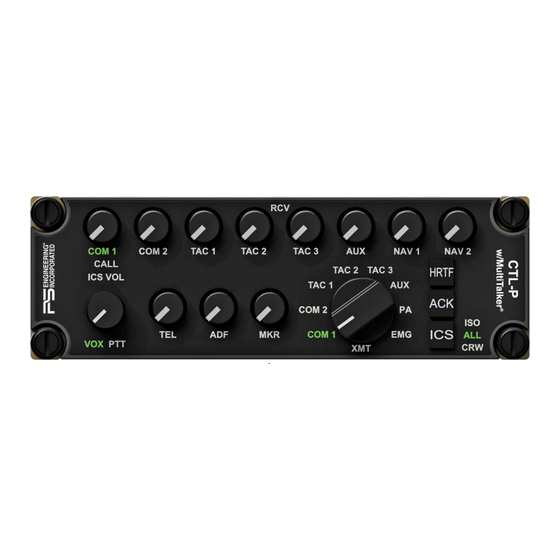
- Page 41 PS Engineering PAC45 Audio Selector Panel and Intercom System Installation and Operator’s Manual 3.9 Dual Control Panel Operation/Pilot & Copilot Figure 3-3 Pilot Control Head, Dual configuration Figure 3-4 Copilot Audio controller, Dual Configuration CTL45P 3.9.1.1 Intercom Operation, Two (Pilot, Copilot) Control Heads If two control heads are used, the following rules apply: •...
- Page 42 PS Engineering PAC45 Audio Selector Panel and Intercom System Installation and Operator’s Manual • Either panel can select ALL and add everybody to the intercom and radio 3.10 Observer/Mission Control Panel Operation (HUB45R S/N LHB01497 & Below, CTL45P is now universal) Some configurations utilize a CTL45M, Observer/Mission control head mounted in the cabin.
- Page 43 PS Engineering PAC45 Audio Selector Panel and Intercom System Installation and Operator’s Manual With the cabin control head is installed, the observer/mission personnel can isolate their audio feed from the crew by pressing the ICS button. When the control head is in ISO mode, the ob- server/passengers will have intercom among themselves, and be able to use the selected radios.
- Page 44 PS Engineering PAC45 Audio Selector Panel and Intercom System Installation and Operator’s Manual INTERCOM MODE – FLIGHT DECK CREW MODE PILOT COPILOT XMIT SEAT XMIT SEAT PASS 1 PASS 2 PASS 3 PASS 4 INTERCOM MODE – MISSION CREW MODE...
- Page 45 PS Engineering PAC45 Audio Selector Panel and Intercom System Installation and Operator’s Manual 3.10.2.1 Dual system isolation If complete separation of the passengers is desired, a switch can be installed in the tie-lines be- tween the HUB45s (see §2.4.11.6) INTERCOM MODE – FLIGHT...
- Page 46 PS Engineering PAC45 Audio Selector Panel and Intercom System Installation and Operator’s Manual 7. When finished with Alert #2, press the “ACK” 8. Now COM3 blinks, to indicate the recording of ALERT #3. 9. Speak message. 10. When finished with Alert #3, press the “ACK”...
- Page 47 PS Engineering PAC45 Audio Selector Panel and Intercom System Installation and Operator’s Manual 3.12 Intercom Operation Block Diagrams These block diagrams illustrate the audio distribution for intercom and radios in four different configurations, single panel, dual panel pilot/copilot, dual panel pilot-copilot/observer, and three control head.
- Page 48 PS Engineering PAC45 Audio Selector Panel and Intercom System Installation and Operator’s Manual DUAL CONTROL HEAD INTERCOM MODES ALL - ALL MODE PILOT ISOLATE MODE ISO-ISO MODE Selected Radios Selected Radios Copilot Intercom Selected Radios Pilot Control Panel Pilot Control Panel...
- Page 49 PS Engineering PAC45 Audio Selector Panel and Intercom System Installation and Operator’s Manual 3.12.3 Dual Control Head Pilot & Copilot CTL45P plus Observer CTL45P (or CTL45M) 200-045-0000 Page 3-3 Rev. 22, June 2024...
- Page 50 PS Engineering PAC45 Audio Selector Panel and Intercom System Installation and Operator’s Manual 3.12.4 Three Control Head, Pilot CTL45, Copilot CTL45P and Mission Observer CTL45P (or CTL45M) 200-045-0000 Page 3-4 Rev. 22, June 2024...
- Page 51 All domestic transportation charges for returning the exchange or repaired unit to the purchaser will be borne by PS Engineering, Inc. The risk of loss or damage to the product is borne by the party making the shipment, unless the purchaser requests a specific method of shipment.
- Page 52 PS Engineering PAC45 Audio Selector Panel and Intercom System Installation and Operator’s Manual Appendix A – PAC45 Installation Drawings Figure 5-1 – PAC45 Rear/Connector View (not to scale) J451: 50-PIN FEMALE ON HARNESS J452: 37-PIN FEMALE ON HARNESS Figure 5-2 – PAC45 Side View...
- Page 53 PS Engineering PAC45 Audio Selector Panel and Intercom System Installation and Operator’s Manual P451 (TOP) P453 (TOP) 50-PIN FEMALE P454 (BOTTOM) 425-050-0967 26-PIN FEMALE 625-050-0967 425-026-1800 P452 (BOTTOM) 625-015-1503 37-PIN FEMALE 425-037-1757 625-037-3703 Figure 5-4 PAC45 Overall 200-045-0000 Appendix A...
- Page 54 PS Engineering PAC45 Audio Selector Panel and Intercom System Installation and Operator’s Manual J455 9-PIN FEMALE 425-009-7709 625-009-9034 Figure 5-5 CTL45 200-045-0000 Appendix A Rev. 22, June 2024...
- Page 55 PS Engineering PAC45 Audio Selector Panel and Intercom System Installation and Operator’s Manual P451 (TOP) 50-PIN FEMALE 425-050-0967 625-050-0967 P452 (BOTTOM) 37-PIN FEMALE P453 (TOP) 425-037-1757 P454 (BOTTOM) 625-037-1757 26-PIN FEMALE 425-026-2161 625-015-1503 Ø0.16 in. X 4 P455 9--PIN MALE...
- Page 56 PS Engineering PAC45 Audio Selector Panel and Intercom System Installation and Operator’s Manual Appendix B – Radio Interconnect Wiring PAC45 Radio Connections P452 P451 Com 1 Audi o Hi COM 1 Com 1 Lo NOT E: See Figure 5-3 Com 1 Mic Audio Hi...
- Page 57 PS Engineering PAC45 Audio Selector Panel and Intercom System Installation and Operator’s Manual Appendix C – Intercom Interconnect Wiring P453 P451 P452 P454 Pil ot Mic Audio Hi Pil ot Mic Lo Pil ot Mic PT T PIL PHN (R)
- Page 58 PS Engineering PAC45 Audio Selector Panel and Intercom System Installation and Operator’s Manual Appendix D – Control Head Interconnect Wiring P 45 5 J4 55 R X- R S422 TX - R X+ R S422 TX + TX- R S422 R X -...
- Page 59 PS Engineering PAC45 Audio Selector Panel and Intercom System Installation and Operator’s Manual Appendix E, Unit Connector Wiring Reference 9.1 J451 Connections P451 PAC45 Connec tors , J451 Com 1 Mic Audio Hi COM 1 Com 1 Mic Key Com 1 Mic Low...
- Page 60 PS Engineering PAC45 Audio Selector Panel and Intercom System Installation and Operator’s Manual 9.2 J452 Connections P452 PAC45 Connector, J452 Com 1 Audio Hi COM 1 Com 1 Lo Com 2 Audio Hi COM 2 Com 2 Audio Low Com 3 Audio Hi...
- Page 61 PS Engineering PAC45 Audio Selector Panel and Intercom System Installation and Operator’s Manual 9.3 J453 Connections P A C 45 C o nnec to rs, J45 3 P453 Com 6 Mic Audio Hi COM 6 Com 6 Mic Key Com 6 Mic Low...
- Page 62 PS Engineering PAC45 Audio Selector Panel and Intercom System Installation and Operator’s Manual 9.4 J454 Connections COM 6 AUDIO HI COM 6 COM 6 AUDIO LO TEL AUDIO HI SATCOM TEL AUDIO LOW TEL MIC AUDIO HI PILOT CVR OUT...
- Page 63 Aircraft equipment list, weights and balance amended. Compass compensation checked. A copy of the operation in- structions, contained in PS Engineering document 202-045-( ), revision ( ), dated ( ), is placed in the aircraft records. All work accomplished listed on Work Order 10.2 Instructions for Continuing Airworthiness, Audio System...
- Page 64 Installation and Operator’s Manual Appendix G – RTCA DO160G Environmental Qualification Form 11.1 Model Number PAC45 Audio Selector Panel/Intercom Remote Hub Part Number: 050-045-( ) FAA TSO Number: C139a, Manufacturer: PS Engineering Incorporated 9800 Martel Road Lenoir City TN 37772 Conditions Section...
- Page 65 PAC45 Audio Selector Panel and Intercom System Installation and Operator’s Manual 11.2 Model Number CTL45, Audio Selector Control Panel Part Number: 050-045-(02XX, -03XX, -62XX, -63XX ) FAA TSO Number: C139a Manufacturer: PS Engineering Incorporated 9800 Martel Road Lenoir City TN 37772 Conditions Section...
Need help?
Do you have a question about the PAC37 and is the answer not in the manual?
Questions and answers