Table of Contents
Advertisement
Quick Links
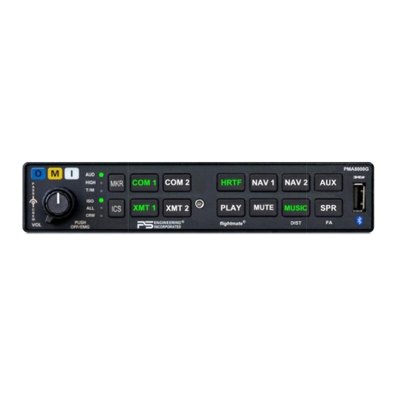
Audio Selector Panel with Marker Beacon Receiver
Audio Selector Panel with Marker Beacon Receiver
Audio Selector Panel with Marker Beacon Receiver
Patented under one or more of the following;
Patented under one or more of the following;
Patented under one or more of the following;
No. 4,941,187; 5,903,227; 6,160,496 and 6,493,450
No. 4,941,187; 5,903,227; 6,160,496 and 6,493,450
No. 4,941,187; 5,903,227; 6,160,496 and 6,493,450
In certified aircraft, warranty is not valid unless this product is installed by an
In certified aircraft, warranty is not valid unless this product is installed by an
In certified aircraft, warranty is not valid unless this product is installed by an
Any reproduction or retransmittal of this publication, or any portion thereof, without the expressed written permission of PS
Any reproduction or retransmittal of this publication, or any portion thereof, without the expressed written permission of PS
Any reproduction or retransmittal of this publication, or any portion thereof, without the expressed written permission of PS
Engineering, Inc. is strictly prohibited. For further information contact the Publications Manager at PS Engineering, Inc., 9800
Engineering, Inc. is strictly prohibited. For further information contact the Publications Manager at PS Engineering, Inc., 9800
Engineering, Inc. is strictly prohibited. For further information contact the Publications Manager at PS Engineering, Inc., 9800
Martel Road, Lenoir City, TN 37772. Phone (865) 988-9800, email contact@ps-engineering.com.
Martel Road, Lenoir City, TN 37772. Phone (865) 988-9800, email contact@ps-engineering.com.
Martel Road, Lenoir City, TN 37772. Phone (865) 988-9800, email contact@ps-engineering.com.
9800 Martel Road
9800 Martel Road
9800 Martel Road
Lenoir City, TN 37772
Lenoir City, TN 37772
Lenoir City, TN 37772
www.ps-engineering.com
www.ps-engineering.com
www.ps-engineering.com
P
P
P
M
M
M
A
A
A
P
P
P
M
M
M
A
A
A
Document P/N 200-890-0912
Document P/N 200-890-0912
Document P/N 200-890-0912
Rev. 7, July 2017
Rev. 7, July 2017
Rev. 7, July 2017
High-fidelity Stereo Intercom with flightmate®
High-fidelity Stereo Intercom with flightmate®
High-fidelity Stereo Intercom with flightmate®
System Installation and Operation Manual
System Installation and Operation Manual
System Installation and Operation Manual
FAA- TSO C50c, C35d, C71
FAA- TSO C50c, C35d, C71
FAA- TSO C50c, C35d, C71
EASA ETSO C50c, 2C35d
EASA ETSO C50c, 2C35d
EASA ETSO C50c, 2C35d
Authorized PS Engineering dealer.
Authorized PS Engineering dealer.
Authorized PS Engineering dealer.
PS Engineering, Inc. 2017 ©
PS Engineering, Inc. 2017 ©
PS Engineering, Inc. 2017 ©
Copyright Notice
Copyright Notice
Copyright Notice
8
8
8
0
0
0
0
0
0
0
0
0
G
G
G
8
8
8
0
0
0
0
0
0
0
0
0
G
G
G
Advertisement
Table of Contents

Related Manuals for PS Engineering PMA8000G


Summary of Contents for PS Engineering PMA8000G
- Page 1 Any reproduction or retransmittal of this publication, or any portion thereof, without the expressed written permission of PS Engineering, Inc. is strictly prohibited. For further information contact the Publications Manager at PS Engineering, Inc., 9800 Engineering, Inc. is strictly prohibited. For further information contact the Publications Manager at PS Engineering, Inc., 9800 Engineering, Inc.
-
Page 2: Table Of Contents
, (S F01256 ) ............... 2-10 ACKLIGHT DJUSTMENTS ERIAL UMBER AND ABOVE ......................2-11 OMMUNICATIONS NTENNA NSTALLATION OTES 2.10 PMA8000G P ............................2-12 IN ASSIGNMENTS 2.11 ................................2-12 IRING HECKOUT 2.12 ................................2-13 NSTALLATION 2.13 ..............................2-13 PERATIONAL HECKOUT 2.13.1 ........................ - Page 3 .................................. 4-1 ACTORY ERVICE Appendix A – External PTT Hook Up ..................A Appendix B – PMA8000G Installation Drawings ................. B Appendix C – J1 Connector Interconnect ..................C Appendix D – J2 Connector Interconnect ..................D Appendix E – Instructions for FAA Form 337 and continuing airworthiness........E...
-
Page 4: Section I - General Information
Pushbutton switches select one of the communication transceivers for the pilot and copilot position, and allow radio transmission. In "Split Mode" the PMA8000G has the ability to allow the pilot to transmit on Com 1 while the copilot can transmit on Com 2. A fail-safe mode connects the pilot headphone and micro- phone to COM 1 if power is removed for any reason, or if the power switch is placed in the Off (Fail-safe) position. -
Page 5: Approval Basis
Intercom squelch is automatic. A 3-light, 75 MHz Marker Beacon receiver is integrated in the PMA8000G. This provides the necessary Marker Beacon lights and audio indications necessary for that portion of an Instrument Landing System (ILS) approach. - Page 6 PS Engineering PMA8000G IntelliAudio Audio Selector Panel With flightmate® Installation and Operator’s Manual Audio Selector Specifications 510 Audio selector panel input impedance: -60 dB (min.) Input Isolation: Speaker Muting: -60 dB (min.) Speaker Output (into 4 ) with no clipping 3 Watts (min.)
-
Page 7: Equipment Supplied
475-632-0012 #6-32 Clip Nut 475-630-0002 EQUIPMENT REQUIRED BUT NOT SUPPLIED Circuit Breaker: 1 ea; 5 amp PULL TYPE REQUIRED for PMA8000G Speaker, 4 Headphone Jacks (Stereo, as Required) Microphone Jacks (as Required) Headphones, 150 (Stereo), up to 6 as required Microphones, up to 6 as required Marker Antenna (75 MHz, VSWR <1:1.5, and appropriate for the airspeed) -
Page 8: Section Ii - Installation
Section 1.6. If any claim is to be made, save the shipping material and con- tact the freight carrier. Do NOT return units damaged in shipping to PS Engineering. If the unit or accesso- ries show any sign of external shipping damage, contact PS Engineering to arrange for a replacement. -
Page 9: Audio Panel Tray And Connector Assembly
There must be at least 13.8 VDC present at the connect- or, J2 pins 8 & 9, of the PMA8000G for the power supply to work in its designed regulation. Otherwise, it cannot adequately attenuate power line noise. -
Page 10: Existing Gma340 Installation
2.4.4 Power The PMA8000G is compatible with both 14 and 28 Volt DC systems. A five (5) Amp circuit breaker is required for all installations. Power and ground wires should be #22 connected to J2 Pins 8 and 9. Connect airframe ground to J2 Pin 10 and 11 only. -
Page 11: Transmit Interlock
2.4.6.1 Speaker Load The PMA8000G contains one speaker amplifier, and does not provide a speaker load for legacy units. Some units with internal speaker amplifiers, such as the King Radio KX170-series, require a resistive load to prevent damage if their speaker amplifier is not used. Connect the speaker output from the legacy radio to an external speaker load of at least 16 , 3W. -
Page 12: Swap" Button Functions
The TEL mode in the PMA8000G is compatible with many telephones with hands-free headset interfaces. A jack can be installed somewhere on the aircraft panel. The wired interface jack is connected with the PMA8000G as shown: A patch cord (3/32” to 3/32”) is available from PS Engineering under P/N 425-006- 7026. -
Page 13: Public Address Mode
2.4.12 Public Address Mode By pressing SPR pushbutton for more than 1 second, the PMA8000G will be placed into public address (PA) mode. SPR light will flash letting the pilot know PA Mode is active. In this mode, the pilot will be talking over the cockpit speaker when he presses his PTT switch. -
Page 14: Storing Messages
2.5.2.1 Audio Alert Messages The PMA8000G has four discrete messages that can be played when triggered by an external event. The recording time is limited to 5 seconds per message. Messages can be stored or changed at anytime, by pressing the front panel buttons that correspond with that alert message. -
Page 15: Entertainment Inputs
Entertainment Inputs Entertainment Inputs The PMA8000G has two INDEPENDENT music inputs, input number 1 is J2 pins 23 (left channel) and 24 The PMA8000G has two INDEPENDENT music inputs, input number 1 is J2 pins 23 (left channel) and 24... -
Page 16: Music Configuration
Radio Recording System playback. This switch can be located anywhere in cockpit convenient to the pilot's reach. The NO switch should be connected to pin 22 of J2 of the PMA8000G, and convenient to the pilot's reach. The NO switch should be connected to pin 22 of J2 of the PMA8000G, and convenient to the pilot's reach. -
Page 17: Middle Marker Sense
Middle Marker Sense A Middle Marker Sense output signal is available from the PMA8000G to certain flight control systems. This function will not operate during the test mode. This output will go to +4.5 VDC ( 1.0 VDC) when a valid Middle Marker signal is received. -
Page 18: Communications Antenna Installation Notes
It is probable that radio interference will occur in the split mode when the frequencies of the two air- craft radios are adjacent, and/or the antennas are physically close together. PS Engineering makes no expressed or implied warranties regarding the suitability of the PMA8000G in Split Mode. -
Page 19: Pma8000G Pin Assignments
After wiring is complete, verify power is ONLY on pins 8 and 9 of the J2 and airframe ground on connect- or pins 10 and 11. Failure to do so will cause serious internal damage and void PS Engineering's warranty. -
Page 20: Unit Installation
2.13 Operational Checkout 2.13.1 Required Test Equipment In order to return an aircraft to service after installation of the PMA8000G, the installer must have access to a Marker Beacon signal generator: IFR NAV401L, NAV402AP, IFR4000 TIC T-30D, T-36C Equivalent test equipment is acceptable as long as the testing requirements can be met. -
Page 21: Marker Checkout
2.13.4 Bluetooth Checkout 2.13.4 Bluetooth Checkout Verify that the PMA8000G will “pair” with a Bluetooth device, and interface with cellular phone and Mu- Verify that the PMA8000G will “pair” with a Bluetooth device, and interface with cellular phone and Mu- Verify that the PMA8000G will “pair”... -
Page 22: Section Iii Operation
This section is divided into sections covering the basic operating areas of the PMA8000G systems. They This section is divided into sections covering the basic operating areas of the PMA8000G systems. They This section is divided into sections covering the basic operating areas of the PMA8000G systems. - Page 23 In normal (not split) modes, the PMA8000G gives priority to the pilot’s radio Push-To-Talk (PTT). If the In normal (not split) modes, the PMA8000G gives priority to the pilot’s radio Push-To-Talk (PTT). If the In normal (not split) modes, the PMA8000G gives priority to the pilot’s radio Push-To-Talk (PTT). If the copilot it transmitting, and the pilot presses his PTT, the pilot’s microphone will be heard over the selected...
-
Page 24: Audio Selector (4)
PS Engineering PMA8000G IntelliAudio Audio Selector Panel With flightmate® Installation and Operator’s Manual NOTE: IntelliAudio requires stereo headsets in pilot and copilot locations with correctly oriented left and right ear cups. 3.2.1.4 Monitor Mode (S/N DG1199 and above) The Monitor Mode causes the audio from a primary radio (selected for transmit) -
Page 25: Intercom Operation
PS Engineering PMA8000G IntelliAudio Audio Selector Panel With flightmate® Installation and Operator’s Manual A pushbutton is used to set the receiver sensitivity and to test the indicator lamps mute the marker audio. Short press – Controls Marker audio on/off. The top indicator (AUD) will light green when selected. The button is backlit white at all times. -
Page 26: Intercom Volume Control (7)
All passenger headsets are connected in parallel. Therefore, if a monaural headset is plugged in to a PMA8000G Stereo installation, one channel will be shorted. Although no damage to the unit will occur, all passengers with stereo headsets will not hear one channel, unless they switch to the “MONO” mode on their headset. -
Page 27: Split Mode Intercom
“Standard Intercom Function.” Alternate Intercom mode is reset at power 3.7 Music and Music Muting (6) The PMA8000G has two independent music inputs at the rear connector. The PMA8000G also has the abil- ity to receive streaming music from a Bluetooth-enabled device. -
Page 28: Music Distribution (Distr)
Mute Off is controlled by the front panel “Mute” button. If the passengers are listen- ing to the music 2 input, their Karaoke Mode is activated by an external switch installed either in the panel, or connected to the AUX button logic output pin on the PMA8000G. 3.7.1... -
Page 29: Music In Pilot Iso Mode
In ISO intercom mode, when the PMA8000G is in the TEL mode, the pilot position is in the "Phone Booth." Only the pilot will hear the telephone, and only he will be heard. He will also have access to Com 1 or 2, and will transmit on that radio using the PTT. -
Page 30: Storing Messages
“Check fuel” J1-24 The recording time is limited. All of the indicators on the PMA8000G will flash indicating that there are three seconds left before system starts to record over the first messages These four messages will play back when the trigger associated with the message number is activated. -
Page 31: Bluetooth® Interface
3.11 USB Charging Port The PMA8000G contains a USB charging port that is capable of providing 5 VDC, 2.1 amps of current (at least 10 watts) to power or charge the batteries in smart phones and tablets used as Personal Electronic De- vices. -
Page 32: Pairing
PMA8000G IntelliAudio Audio Selector Panel With flightmate® Installation and Operator’s Manual 3.13.1 Pairing To pair the PMA8000G with PS Streamer, press and hold the AUX and SPR buttons at the same time. The Bluetooth indicator will flash quickly, then more slowly as the pairing process progresses, and finally illuminate solid when the process is complete. -
Page 33: Streaming Source Selection
PS Engineering PMA8000G IntelliAudio Audio Selector Panel With flightmate® Installation and Operator’s Manual 3.13.4 Streaming Source Selection The output can contain either the audio heard by the pilot (radio, intercom, music, etc.) or com- munications radio audio. Press and hold the MUSIC & SPR button until you hear “COM Audio” in the headset, to select communication radio only. -
Page 34: Section Iv - Warranty And Service
(3) years from the date of sale. During the first twelve (12) months of the three-year warranty pe- riod, PS Engineering, Inc., at its option, will send a replacement unit at our expense if the unit should be determined to be defective after consultation with a factory technician. -
Page 35: Appendix A - External Ptt Hook Up
PS Engineering PMA8000G IntelliAudio Audio Selector Panel With flightmate® Installation and Operator’s Manual Appendix A – External PTT Hook Up Part of the installation includes the installation of PTT (Push to Talk) switches that allow the use of your aircraft radio for communications transmissions. -
Page 36: Appendix B - Pma8000G Installation Drawings
PS Engineering PMA8000G IntelliAudio Audio Selector Panel With flightmate® Installation and Operator’s Manual Appendix B – PMA8000G Installation Drawings Ground Lug 475-440-0001 (x2) Back plate assy 475-440-0001 (x2) Screw w/washer 475-009-0001 Viewed from Back ground lug (x2) Ground Lug Ground lug detail Rear plate detail (not to scale) 6.31in... -
Page 37: Appendix C - J1 Connector Interconnect
PS Engineering PMA8000G IntelliAudio Audio Selector Panel With flightmate® Installation and Operator’s Manual Appendix C – J1 Connector Interconnect PMA8000G Connector, J1 (Sub-D 44-pin, male on tray) Com 1 Audio Hi Notes: Communications Com 1 Lo 1. All shields should be grounded at audio panel only. -
Page 38: Appendix D - J2 Connector Interconnect
PS Engineering PMA8000G IntelliAudio Audio Selector Panel With flightmate® Installation and Operator’s Manual Appendix D – J2 Connector Interconnect PMA8000C J2 CONNECTOR Pilot Phones (R) Pilot PhonesJack Pilot Phones (L) (Sub-D 44-pin male on tray) Pilot Phones Lo Copilot Phones (R) -
Page 39: Appendix E - Instructions For Faa Form 337 And Continuing Airworthiness
Aircraft equipment list, weights and balance amended. Compass compensation checked. A copy of the operation instruc- tions, contained in PS Engineering document 202-890-( ), revision ( ), dated ( ), is placed in the aircraft records. All work accomplished listed on Work Order 8.2 Instructions for Continuing Airworthiness, Audio System... -
Page 40: Appendix F - Rtca Do160D Environmental Qualification Form
PS Engineering PMA8000G IntelliAudio Audio Selector Panel With flightmate® Installation and Operator’s Manual Appendix F – RTCA DO160D Environmental Qualification Form Audio Selector Panel/Intercom/Marker Beacon Receiver Part Number: 050-890-091( ) FAA TSO Number: C50c, C35d C71 Manufacturer: PS Engineering Incorporated 9800 Martel Road...
Need help?
Do you have a question about the PMA8000G and is the answer not in the manual?
Questions and answers