
Related Manuals for Sam4s SPT-7000 Series


Summary of Contents for Sam4s SPT-7000 Series
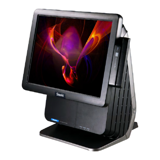
- Page 1 Help Print Exit Rev.1.00.1204.K e-Manual SPT - 7000 series Leading the way with Reliability, Features and Value...
- Page 2 Thank you for your purchase of Sam4s POS terminal. Alert massage & symbol Appendix A Unpacking This e-Manual provides you with technical information such as electrical circuit, components and structure regarding Sam4s POS (Point of Sale) System SPT-7000. System Features Print e-Manual page Part Name and Function System Set-Up The outer design or specifications are subject to change for quality improvement without prior notice.
- Page 3 HOME Contents Help Print Exit E-Manual SPT-7000 series PDF electronic manual consists of System Instruction, System Installation, System Use, System Setup, System Expansion and Appendix a/b. Contents Introduction System Installation System Use System Expansion Appendix A Appendix B ▼ ▼ ▼...
- Page 4 References Alert massage & symbol Unpacking This e-Manual provides you with technical information such as electrical circuit, components and structure regarding Sam4s POS (Point of Sale) System SPT-7000. System Features Part Name and Function The outer design or specifications are subject to change for quality improvement without prior notice.
- Page 5 Part Name and Function The copyright of the e-Manual is in Sam4s. Some equipment nomenclature and abbreviations used here may differ from that contained in other Sam4s publications. System Installation This device complies with part 15 of the FCC Rules. (Class A digital device) ▶...
- Page 6 HOME Contents Help Print Exit SPT-7000 Introduction 01. Notificaton Introduction ▼ Notification Alert massage & symbol Notification This manual uses the following conventions to show the alert messages. An alert message consists of an alert signal and alert statements. References The alert signal consists of an alert symbol and a signal word or just a signal word.
- Page 7 HOME Contents Help Print Exit SPT-7000 Introduction 02. Unpacking Introduction ▼ Notification Unpacking System Features Part Name and Function System Installation ▶ System Use ▶ System Expansion ▶ & Dismantle Appendix A <Mouse / Mouse Pad (Option)> <Keyboard (Option)> System Set-Up Appendix B System Structure <System Terminal>...
- Page 8 HOME Contents Help Print Exit SPT-7000 Introduction 03. System Features Introduction ▼ System Introduction Notification Unpacking System Features This POS system supports All-in-one type and Separable type. Also, you can organize the cables easily in any surrounding. System Introduction System Features This POS system can make all-in-one touch screen, internal printer, MSR, SCR and customer display.
- Page 9 HOME Contents Help Print Exit SPT-7000 Introduction System Features Introduction ▼ System Specifications Notification Unpacking System Features General Specifications System Introduction Dimension 267(357) X 310 X 387(447) ( ):With Display System Features System Specifications Weight 11.5 Kgs (based on standard specification) Part Name and Function Processor CPU : Intel Atom Cedarview D2550 1.86GHZ (Dual Core) FANLESS HEAT SINK...
- Page 10 HOME Contents Help Print Exit SPT-7000 Introduction System Features Introduction ▼ System Specifications Notification Unpacking System Features General Specifications System Introduction System Features TFT LCD, LVDS Interface System Specifications Resolution & Colors : 1024 x 768 (XGA), 16.2M (RGB) Color Part Name and Function Contrast Ratio : 450 : 1 Display...
- Page 11 HOME Contents Help Print Exit SPT-7000 Introduction System Features Introduction ▼ System Specifications Notification Unpacking System Features Specifications for Optional Devices System Introduction System Features 2-inch / 3-inch Thermal Printer Power Supply System Specifications USB Interface 60W Adaptor Part Name and Function Receipt Printer 220mm/sec (3-inch), 150mm/sec (2-inch) speed AC INPUT : AC 100V ~ 240V / 50Hz ~ 60Hz 1.5A...
- Page 12 HOME Contents Help Print Exit SPT-7000 Introduction 04. Part Name and Function Introduction ▼ Front View Notification Unpacking System Features Part Name and Function Front View Half-Side View Side View Rear View System Installation Payment Module Light ▶ When MSR is used, the light will be lit. System Use ▶...
- Page 13 HOME Contents Help Print Exit SPT-7000 Introduction Part Name and Function Introduction ▼ Half-Side View Notification Unpacking System Features Part Name and Function Front View Half-Side View Side View Rear View System Installation ▶ System Use ▶ Speaker Cover Hard Disk Drive Cover System Expansion ▶...
- Page 14 HOME Contents Help Print Exit SPT-7000 Introduction 04. Part Name and Function Introduction ▼ Side View Notification Unpacking System Features Part Name and Function Front View Half-Side View Side View Rear View System Installation ▶ System Use ▶ USB Port For connecting USB Interface such as System Expansion USB Keyboard, Mouse etc.
- Page 15 HOME Contents Help Print Exit SPT-7000 Introduction Part Name and Function Introduction ▼ Rear View Notification Unpacking System Features Part Name and Function Front View Half-Side View Side View Rear View All-in-one Customer Display Cover System Installation Remove this cover and you can install customer display ▶...
- Page 16 HOME Contents Help Print Exit SPT-7000 Introduction 04. Part Name and Function Introduction ▼ Rear View Notification Unpacking System Features Part Name and Function Front View Half-Side View Side View Rear View RJ45 LAN Port For connecting RJ45 cable to use DSUB 9 pin / RJ45 Serial Port 10/100/1,000 Mbps Ethernet System Installation...
- Page 17 HOME Contents Help Print Exit SPT-7000 System Installation 01. Make sure of installation area It is important to be sure the installed place is safe and comportable like following contents before setup the system. Introduction ▶ System Installation ▼ Make sure of Choose a big and solid desk or table to support the weight of this system.
- Page 18 HOME Contents Help Print Exit SPT-7000 System Installation 02. Before connecting peripherals First remove Interface Cover at the rear of the system. Introduction ▶ System Installation Connecting Peripherals ▼ Make sure of Remove Interface Cover installation area Before connecting Pushing the both lock buttons, pull the Interface Cover and remove it. peripherals Connecting Peripherals System On / Off...
- Page 19 System On / Off System Use ▶ System Expansion ▶ & Dismantle Appendix A We recommend you to use Sam4s Cash Drawer because of System Set-Up Note! different cable specifications by each manufacturer. <Cash Drawer> Appendix B System Structure ◀ 2 - 3 ▶...
- Page 20 HOME Contents Help Print Exit SPT-7000 System Installation 03. Connecting Peripherals Introduction ▶ System Installation Connecting RJ-45 LAN Cable ▼ Make sure of RJ-45 LAN or Internet-enabled cable can be connected. installation area It supports 10/100/1000Mbps. Before connecting peripherals Connecting Peripherals <LAN Hub>...
- Page 21 HOME Contents Help Print Exit SPT-7000 System Installation 03. Connecting Peripherals Introduction ▶ System Installation Connecting PS Module (Option) ▼ Make sure of In case using MSR, after removing side cover which is located at the right side of LCD, then connect the module. installation area The module is easily connected as USB connector type.
- Page 22 HOME Contents Help Print Exit SPT-7000 System Installation 03. Connecting Peripherals Introduction ▶ System Installation Connecting Security/Scanner Module (Option) ▼ Make sure of In case using Fingerprint / Dallas / Scanner / Smart Card Reader (SCR), after removing installation area the cover which is located at the right bottom and then connect the module.
- Page 23 HOME Contents Help Print Exit SPT-7000 System Installation 03. Connecting Peripherals Introduction ▶ System Installation Receipt Printer ▼ Install & Test – Install Partition Make sure of installation area 58mm printing paper can be used in case of installing partition. Before connecting peripherals 1.
- Page 24 HOME Contents Help Print Exit SPT-7000 System Installation 03. Connecting Peripherals Introduction ▶ System Installation Receipt Printer ▼ Install & Test – Install and Replace Paper Roll Make sure of installation area Before connecting peripherals Make sure to use paper rolls that meet the standard. Note! Connecting Peripherals Non-standard paper rolls may cause printer malfunction.
- Page 25 HOME Contents Help Print Exit SPT-7000 System Installation 03. Connecting Peripherals Introduction ▶ System Installation Receipt Printer ▼ Install & Test – Self-Test Make sure of installation area Before connecting peripherals Self-Test Mode Connecting Peripherals Self-Test can check products for defects or disorder. The procedure for Self-Test is as follows.
- Page 26 HOME Contents Help Print Exit SPT-7000 System Installation 03. Connecting Peripherals Introduction ▶ System Installation Receipt Printer ▼ Use Function – Paper Feed Button & LED Make sure of installation area Before connecting peripherals Connecting Peripherals Paper Feed Button Connecting Serial Port Devices This button can be disabled by the ESC c 5 command.
- Page 27 HOME Contents Help Print Exit SPT-7000 System Installation 03. Connecting Peripherals Introduction ▶ System Installation Receipt Printer ▼ Maintenance Make sure of installation area Before connecting peripherals Dust can make a falling-off in printing quality. Please clean the printer with following procedure. Connecting Peripherals Connecting Serial Port Devices such as Barcode Scanner...
- Page 28 HOME Contents Help Print Exit SPT-7000 System Installation 03. Connecting Peripherals Introduction ▶ System Installation Receipt Printer ▼ Error Status & Error Resolution – Cover Open & No Paper Make sure of installation area The printer beeps the buzzer or continuously the error LED blinks when it enters the ERROR status. Before connecting peripherals When the cover is not closed completely (Cover Open)
- Page 29 HOME Contents Help Print Exit SPT-7000 System Installation 03. Connecting Peripherals Introduction ▶ System Installation Receipt Printer ▼ Error Status & Error Resolution – Cutter Jam Make sure of installation area Before connecting peripherals Cutter Jam Connecting Peripherals The cutter blade cannot proceed forward normally due to some objects are stuck in the printer inside while operating. Connecting Serial Port Devices like“Beep Beep ---, Beep Beep ---”and LED turns on Green / Red light alternately.
- Page 30 HOME Contents Help Print Exit SPT-7000 System Installation 03. Connecting Peripherals Introduction ▶ System Installation Receipt Printer ▼ Error Status & Error Resolution – Cutter Not Home Make sure of installation area Before connecting peripherals Cutter Not Home Connecting Peripherals This happens if the cutter blade steps forward while the printer is on (LED is light on).
- Page 31 HOME Contents Help Print Exit SPT-7000 System Installation 03. Connecting Peripherals Introduction ▶ System Installation Receipt Printer ▼ Error Status & Error Resolution – Error Resolution Make sure of installation area Before connecting peripherals Cutter Jam / Cutter Not Home Connecting Peripherals 1.
- Page 32 HOME Contents Help Print Exit SPT-7000 System Installation 03. Connecting Peripherals Introduction ▶ System Installation Receipt Printer ▼ Error Status & Error Resolution – Error Resolution Make sure of installation area Before connecting Note! ▶ If you cannot solve“Cutter Jam”or“Cutter Not Home”errors by the method mentioned in page 2-15, peripherals ▶...
- Page 33 HOME Contents Help Print Exit SPT-7000 System Installation 03. Connecting Peripherals Introduction ▶ System Installation Dismantle the Cover for Customer Displays (Option) ▼ After dismantling the cover, connect CDP / 7 Dual LCD / 15 Dual LCD into the system. Make sure of installation area Refer to System Disassembly / Assembly of System Expansion.
- Page 34 HOME Contents Help Print Exit SPT-7000 System Installation 03. Connecting Peripherals Introduction ▶ System Installation Connect DVR Card ▼ 1. Push the both lock button of the rear cover and then pull the cover as shown. Make sure of installation area 2.
- Page 35 Connecting USB Device Connecting PS Module Connecting Security / Scanner Module Connecting Receipt Printer ▶ SPT-7000 Adaptor from Sam4s should be only used. Caution! Receipt Printer Dismantle the Cover ▶ Never use the adaptor with similar specification or shape. for Customer Displays...
- Page 36 HOME Contents Help Print Exit SPT-7000 System Installation 03. Connecting Peripherals Introduction ▶ System Installation Cable Management ▼ 1. Manage cables using the Stand Rib and close the Interface cover. Make sure of installation area Before connecting peripherals Connecting Peripherals Connecting Serial Port Devices such as Barcode Scanner Connecting RJ-11 Cash Drawer...
- Page 37 HOME Contents Help Print Exit SPT-7000 System Installation 04. System On / Off Introduction ▶ System Installation System On ▼ Make sure of After installation of the system, proceed to power on the system with following steps. installation area Before connecting peripherals Connecting Peripherals 1.
- Page 38 HOME Contents Help Print Exit SPT-7000 System Installation 04. System On / Off Introduction ▶ System Installation System Off ▼ Make sure of installation area Before connecting 1. All application programs should be off after saving files. peripherals 2. Press <Start> button and select Turn Off Computer on popup menu. Connecting Peripherals System On / Off System On...
- Page 39 HOME Contents Help Print Exit SPT-7000 System Use 01. Keyboard Using Key board is used for inputting data, it consists of letter keys, number keys, and special keys. Introduction ▶ Keyboard function is depends on the model type the customer purchase. If you want to use PS/2 keyboard type, please connect keyboard when the system powered off. System Installation ▶...
- Page 40 HOME Contents Help Print Exit SPT-7000 System Use 02. Touch Screen Use Introduction Recalibrate if it is not accurate on touch points. ▶ System Installation ▶ To recalibrate the touch screen, please follow the procedure blow. System Use ▼ Click the right button of mouse on elo icon of Windows tray icons. And select Align tab on the menu.
- Page 41 HOME Contents Help Print Exit SPT-7000 System Use 02. Touch Screen Use Introduction Recalibrate if it is not accurate on touch points. ▶ System Installation ▶ System Use ▼ If the recalibration is finished, click the green check button and end the recalibration program. Keyboard Use Touch screen Use About POS Driver and Utility...
- Page 42 HOME Contents Help Print Exit SPT-7000 System Use 03. About POS Driver & Utility Introduction ▶ System Installation ▶ POS Driver and Utility System Use POS Driver & Other utilities are in Util_Driver folder of C driver. ▼ Keyboard Use Touch screen Use About POS Driver and Utility Dual Monitor Use...
- Page 43 HOME Contents Help Print Exit SPT-7000 System Use 03. About POS Driver & Utility Introduction ▶ System Installation ▶ POS Driver and Utility System Use POS Driver & Other utilities are in Util_Driver folder of C driver. ▼ Keyboard Use Touch screen Use About POS Driver and Utility Dual Monitor Use...
- Page 44 HOME Contents Help Print Exit SPT-7000 System Use 03. About POS Driver & Utility Introduction ▶ System Installation ▶ POS Driver and Utility System Use OPOS or OLE Retail POS consists of an architecture for win32-based POS device access. ▼ The current OPOS driver has been developed in accordance with OPOS Specification Version 1.10 and continues to support the OPOS version.
- Page 45 HOME Contents Help Print Exit SPT-7000 System Use 04. Dual Monitor Use Additional monitor can be connected to the VGA connector. This contents is written based on Windows 7 OS. Introduction ▶ System Installation ▶ The system supports dual monitors that is using two monitors for one system. Sub-monitor can be displayed a screen copied a main-monitor s Windows desktop or can be display a screen extended Windows desktop.
- Page 46 HOME Contents Help Print Exit SPT-7000 System Use 04. Dual Monitor Use Additional monitor can be connected to the VGA connector. This contents is written based on Windows 7 OS. Introduction ▶ System Installation ▶ System Use ▼ Click the right button of mouse on Windows desktop screen, and select Screen resolution from a popup menu. Keyboard Use Touch screen Use About POS Driver and Utility...
- Page 47 HOME Contents Help Print Exit SPT-7000 System Use 04. Dual Monitor Use Introduction Additional monitor can be connected to the VGA connector. This contents is written based on Windows 7 OS. ▶ System Installation ▶ System Use ▼ On Change the appearance of your display dialog, Keyboard Use the Display option is set as 1|2 Multiple Monitors and Multiple displays Touch screen Use...
- Page 48 HOME Contents Help Print Exit SPT-7000 System Use 04. Dual Monitor Use Introduction Additional monitor can be connected to the VGA connector. This contents is written based on Windows 7 OS. ▶ System Installation ▶ System Use ▼ If you want to change to an extended screen, set Multiple displays Keyboard Use option as Extend these displays on Change the appearance of your display dialog.
- Page 49 HOME Contents Help Print Exit SPT-7000 System Use 04. Dual Monitor Use Introduction Additional monitor can be connected to the VGA connector. This contents is written based on Windows 7 OS. ▶ System Installation ▶ System Use ▼ Set Display option as 1. Digital Flat Panel (1024x768 60 Hz) Keyboard Use and click Apply button.
- Page 50 HOME Contents Help Print Exit SPT-7000 System Use 04. Dual Monitor Use Introduction Additional monitor can be connected to the VGA connector. This contents is written based on Windows 7 OS. ▶ System Installation ▶ System Use ▼ . Select Keep changes button on Display Settings dialog to keep the current settings. Keyboard Use Touch screen Use About POS Driver and Utility...
- Page 51 HOME Contents Help Print Exit SPT-7000 System Use 04. Dual Monitor Use Introduction Additional monitor can be connected to the VGA connector. This contents is written based on Windows 7 OS. ▶ System Installation ▶ System Use ▼ If the configuration is finished, click OK button to close Keyboard Use Touch screen Use the Change the appearance of your displays dialog.
- Page 52 HOME Contents Help Print Exit SPT-7000 System Use 04. Dual Monitor Use Introduction Additional monitor can be connected to the VGA connector. This contents is written based on Windows 7 OS. ▶ System Installation ▶ ▶ How to check dual monitor’s settings Note! System Use ▼...
- Page 53 HOME Contents Help Print Exit SPT-7000 System Expansion & Dismantle 01. System Dismantling & Assembling Introduction ▶ System Installation System Dismantling ▶ 1. Press the lock button then, pull“I/F cover”toward the arrow direction & take it from the body. System Use ▶...
- Page 54 HOME Contents Help Print Exit SPT-7000 System Expansion & Dismantle 01. System Dismantling & Assembling Introduction ▶ System Installation Customer Display Assembling & Dismantling (CDP) ▶ 1. Press the lock button then, pull I/F cover toward the arrow direction like System Use ▶...
- Page 55 HOME Contents Help Print Exit SPT-7000 System Expansion & Dismantle 01. System Dismantling & Assembling Introduction ▶ System Installation Customer Display Assembling & Dismantling (CDP) ▶ 3. Equip the body with Customer Display with the cable. System Use ▶ System Expansion ▼...
- Page 56 HOME Contents Help Print Exit SPT-7000 System Expansion & Dismantle 01. System Dismantling & Assembling Introduction ▶ System Installation Customer Display Assembling & Dismantling (DUAL 7”) ▶ 1. Press the lock button then, pull I/F cover toward the arrow direction like System Use ▶...
- Page 57 HOME Contents Help Print Exit SPT-7000 System Expansion & Dismantle 01. System Dismantling & Assembling Introduction ▶ Customer Display Assembling & Dismantling (DUAL 7 ) System Installation ▶ 3. Clamp a hook for the cable to the body with screw. Put the cable inside of the hook after equipping the system with the Customer display (7 ) System Use ▶...
- Page 58 HOME Contents Help Print Exit SPT-7000 System Expansion & Dismantle 01. System Dismantling & Assembling Introduction ▶ System Installation Customer Display Assembling & Dismantling (DUAL 15 ) ▶ 1. Press the lock button then, pull the cover toward the arrow direction to take it from the body. System Use ▶...
- Page 59 HOME Contents Help Print Exit SPT-7000 System Expansion & Dismantle 01. System Dismantling & Assembling Introduction ▶ System Installation Customer Display Assembling & Dismantling (DUAL 15 ) ▶ 3. Clamp a hook for the cable to the body with screw. Put the cable inside of the hook after equipping the system with the Customer display (15 ) System Use ▶...
- Page 60 HOME Contents Help Print Exit SPT-7000 System Expansion & Dismantle 01. System Dismantling & Assembling Introduction ▶ System Installation SMPS Replacement with DUAL Monitor (15 ) ▶ 1. Lay down the body with care. System Use ▶ System Expansion ▼ &...
- Page 61 HOME Contents Help Print Exit SPT-7000 System Expansion & Dismantle 01. System Dismantling & Assembling Introduction ▶ System Installation SMPS Replacement with DUAL Monitor (15 ) ▶ 4. Remove a screw on the top and the bracket top from the body. System Use ▶...
-
Page 62: Hdd Replacement
HOME Contents Help Print Exit SPT-7000 System Expansion & Dismantle 02. HDD Replacement Introduction ▶ System Installation ▶ You can only use 2.5 inch SATA type HDD for the system. System Use ▶ 1. Make sure the system is off for the replacement. 2. - Page 63 HOME Contents Help Print Exit SPT-7000 System Expansion & Dismantle 02. HDD Replacement Introduction ▶ System Installation ▶ You can only use 2.5 inch SATA type HDD for the system. System Use ▶ 4. Remove the bracket from the HDD. System Expansion ▼...
- Page 64 HOME Contents Help Print Exit SPT-7000 System Expansion & Dismantle 03. Internal Speaker & USB Removal Introduction ▶ System Installation ▶ 1. Turn off the system. System Use ▶ 2. Push up the display & push the cover speaker to the right to remove it from the body. System Expansion ▼...
- Page 65 HOME Contents Help Print Exit SPT-7000 System Expansion & Dismantle 04. Receipt Printer & Board Removal Introduction ▶ System Installation Receipt Printer & Board Removal ▶ System Use ▶ 1. Turn off the system before the receipt printer removal. 2. Push up the display & take out the cover cutter with grip. Then, open the cover printer. System Expansion ▼...
- Page 66 HOME Contents Help Print Exit SPT-7000 System Expansion & Dismantle 04. Receipt Printer & Board Removal Introduction ▶ System Installation Receipt Printer & Board Removal ▶ System Use ▶ 4. Assemble the dummy printer, when it does not apply the receipt printer. Hang the hook of the dummy printer &...
- Page 67 HOME Contents Help Print Exit SPT-7000 System Expansion & Dismantle 04. Receipt Printer & Board Removal Introduction ▶ System Installation Receipt Printer Assembling ▶ System Use 1. Assemble in reverse order. Join the connector then tilt the printer at an angle of 15 degrees, then push in the upper side of printer first, then push in the printer cover. ▶...
- Page 68 HOME Contents Help Print Exit SPT-7000 System Expansion & Dismantle 04. Receipt Printer & Board Removal Introduction ▶ System Installation Printer Board Removal ▶ 1. Remove screws(2) to remove the printer board. System Use ▶ System Expansion ▼ & Dismantle System Dismantling &...
- Page 69 HOME Contents Help Print Exit SPT-7000 System Expansion & Dismantle 05. Scanner & Dallas Option Removal Introduction ▶ System Installation Scanner & Dallas Removal ▶ System Use ▶ 1. Turn off the system. 2. Push up the display. System Expansion ▼...
- Page 70 HOME Contents Help Print Exit SPT-7000 System Expansion & Dismantle 05. Scanner & Dallas Option Removal Introduction ▶ System Installation Scanner & Dallas Removal ▶ System Use ▶ 1. Assemble the dummy printer, when it does not apply Scanner / Dallas options. System Expansion ▼...
- Page 71 HOME Contents Help Print Exit SPT-7000 System Expansion & Dismantle 05. Scanner & Dallas Option Removal Introduction ▶ System Installation HUB board & IC card Removal ▶ System Use ▶ 1. Remove screws(2) to remove the HUB board 2. Remove screws(2) to remove IC card. System Expansion ▼...
- Page 72 HOME Contents Help Print Exit SPT-7000 System Expansion & Dismantle 05. Scanner & Dallas Option Removal Introduction ▶ System Installation OSD board Removal ▶ System Use ▶ 1. Unscrew screws(2) & remove the scanner bracket. 2. Unscrew screw(1) & remove the bracket. System Expansion ▼...
- Page 73 HOME Contents Help Print Exit SPT-7000 System Expansion & Dismantle 06. SMPS Removal Introduction ▶ System Installation SMPS Removal ▶ System Use ▶ 1. Turn off the system. 2. Lay the system down with care to protect the LCD panel. System Expansion ▼...
- Page 74 HOME Contents Help Print Exit SPT-7000 System Expansion & Dismantle 06. SMPS Removal Introduction ▶ System Installation SMPS Removal ▶ System Use ▶ 4. Pull the bracket handle towards you to remove the SMPS. System Expansion ▼ & Dismantle System Dismantling &...
- Page 75 HOME Contents Help Print Exit SPT-7000 System Expansion & Dismantle 07. Mainboard ASSY Removal Introduction ▶ System Installation Mainboard ASSY Removal ▶ System Use ▶ 1. Turn off the system. ※ Power & other cables must be removed before dismantling the system. System Expansion ▼...
- Page 76 HOME Contents Help Print Exit SPT-7000 System Expansion & Dismantle 07. Mainboard ASSY Removal Introduction ▶ System Installation Mainboard ASSY Removal ▶ System Use ▶ 4. Remove harness & unscrew the screws(2) in both sides. 5. Hold the I / F bracket & push it up to unlock. Then, remove it. System Expansion ▼...
- Page 77 HOME Contents Help Print Exit SPT-7000 System Expansion & Dismantle 08. Various Boards Removal Introduction ▶ System Installation CFAST Board Removal ▶ System Use ▶ 1. Remove the screws(2) to remove CFAST board. System Expansion ▼ & Dismantle System Dismantling &...
- Page 78 HOME Contents Help Print Exit SPT-7000 System Expansion & Dismantle 08. Various Boards Removal Introduction ▶ System Installation Parallel Board Removal ▶ System Use ▶ 1. Remove 4 screws to remove Parallel board. System Expansion ▼ & Dismantle System Dismantling &...
- Page 79 HOME Contents Help Print Exit SPT-7000 System Expansion & Dismantle 08. Various Boards Removal Introduction ▶ System Installation VFD Board Removal ▶ System Use ▶ 1. Refer to the pictures. 2. Remove a screw to remove VFD board. System Expansion ▼...
- Page 80 HOME Contents Help Print Exit SPT-7000 System Expansion & Dismantle 08. Various Boards Removal Introduction ▶ System Installation WIFI Board Removal ▶ System Use ▶ 1. Remove the front cover like the first picture. 2. Push up the covers in both sides to remove. System Expansion ▼...
- Page 81 HOME Contents Help Print Exit SPT-7000 System Expansion & Dismantle 09. Main Memory Removal Introduction ▶ System Installation Main Memory Removal ▶ System Use You might need to extend the memory capacity. ▶ You need to check the specification of the main & extended memory when you extend the main memory. System Expansion ▼...
- Page 82 HOME Contents Help Print Exit SPT-7000 System Expansion & Dismantle 10. Remove Display Assembly Introduction ▶ System Installation Remove Display Assembly ▶ System Use 1. Turn off the system. ▶ ※ Remove cables for power before disassembly, System Expansion ▼ 2.
- Page 83 HOME Contents Help Print Exit SPT-7000 System Expansion & Dismantle 11. Remove MSR Introduction ▶ System Installation Disassembly of MSR ▶ System Use 1. Unscrew a screw. Push to the left and disassemble it. ▶ System Expansion ▼ & Dismantle System Dismantling &...
- Page 84 HOME Contents Help Print Exit SPT-7000 System Expansion & Dismantle 12. Remove Display Board Introduction ▶ System Installation Remove Display Board (Inverter, MSR, Touch) ▶ System Use 1. Unscrew a screw by hand and disassemble by moving Cover Top (Up) and Cover Bottom (Down). ▶...
- Page 85 HOME Contents Help Print Exit SPT-7000 System Expansion & Dismantle 12. Remove Display Board Introduction ▶ System Installation Remove Inverter ▶ System Use 1. Remove all the connected harness. ▶ 2. Unscrew 2 screws and disconnect Inverter. System Expansion ▼ &...
- Page 86 HOME Contents Help Print Exit SPT-7000 System Expansion & Dismantle 13. Remove Touch Panel & LCD Introduction ▶ Remove Touch Panel & LCD System Installation ▶ ▶ It may happen defectives while disconnecting LCD and Touch Panel due to dust or mishandling. Caution! System Use ▶...
- Page 87 HOME Contents Help Print Exit SPT-7000 BIOS Set-up 01. BIOS Set-up Preview Set-up means that the system configuration information is memorized on ‘BIOS’. Introduction The set-up data is saved in a special area of memory called CMOS ROM. ▶ System Installation ▶...
- Page 88 HOME Contents Help Print Exit SPT-7000 BIOS Set-up 01. System Set-up Preview Set-up means that the system configuration information is memorized on ‘BIOS’. Introduction ▶ The set-up data is saved in a special area of memory called CMOS ROM. Initial Setup Screen System Installation ▶...
- Page 89 HOME Contents Help Print Exit SPT-7000 BIOS Set-up 01. System Set-up Preview Set-up means that the system configuration information is memorized on ‘BIOS’. Introduction The set-up data is saved in a special area of memory called CMOS ROM. ▶ System Installation ▶...
-
Page 90: Main Menu
HOME Contents Help Print Exit SPT-7000 BIOS Set-up 02. Main Menu Introduction Use this menu for basic system setup such as time, date and etc. and system information. ▶ System Installation ▶ System Use ▶ System Expansion & Dismantle Appendix A System Set-Up ▼... - Page 91 HOME Contents Help Print Exit SPT-7000 BIOS Set-up 03. Advanced Menu Introduction Use this menu for basic system setup such as time, date and etc. and system information. ▶ System Installation ▶ System Use ▶ System Expansion & Dismantle Appendix A System Set-Up ▼...
- Page 92 HOME Contents Help Print Exit SPT-7000 BIOS Set-up 03. Advanced Menu Introduction Use this menu for basic system setup such as time, date and etc. and system information. ▶ System Installation ▶ System Use ▶ System Expansion & Dismantle Appendix A System Set-Up ▼...
- Page 93 HOME Contents Help Print Exit SPT-7000 BIOS Set-up 03. Advanced Menu Introduction Use this menu for basic system setup such as time, date and etc. and system information. ▶ System Installation ▶ System Use ▶ System Expansion & Dismantle Appendix A System Set-Up ▼...
- Page 94 HOME Contents Help Print Exit SPT-7000 BIOS Set-up 03. Advanced Menu Introduction Use this menu for basic system setup such as time, date and etc. and system information. ▶ System Installation ▶ System Use ▶ System Expansion & Dismantle Appendix A System Set-Up ▼...
- Page 95 HOME Contents Help Print Exit SPT-7000 BIOS Set-up 03. Advanced Menu Introduction Use this menu for basic system setup such as time, date and etc. and system information. ▶ System Installation ▶ System Use ▶ System Expansion & Dismantle Appendix A System Set-Up ▼...
- Page 96 HOME Contents Help Print Exit SPT-7000 BIOS Set-up 03. Advanced Menu Introduction Use this menu for basic system setup such as time, date and etc. and system information. ▶ System Installation ▶ System Use ▶ System Expansion & Dismantle Appendix A System Set-Up ▼...
- Page 97 HOME Contents Help Print Exit SPT-7000 BIOS Set-up 03. Advanced Menu Introduction Use this menu for basic system setup such as time, date and etc. and system information. ▶ System Installation ▶ System Use ▶ System Expansion & Dismantle Appendix A System Set-Up ▼...
- Page 98 HOME Contents Help Print Exit SPT-7000 BIOS Set-up 03. Advanced Menu Introduction Use this menu for basic system setup such as time, date and etc. and system information. ▶ System Installation ▶ System Use ▶ System Expansion & Dismantle Appendix A System Set-Up ▼...
- Page 99 HOME Contents Help Print Exit SPT-7000 BIOS Set-up 03. Advanced Menu Introduction Use this menu for basic system setup such as time, date and etc. and system information. ▶ System Installation ▶ System Use ▶ System Expansion & Dismantle Appendix A System Set-Up ▼...
- Page 100 HOME Contents Help Print Exit SPT-7000 BIOS Set-up 03. Advanced Menu Introduction Use this menu for basic system setup such as time, date and etc. and system information. ▶ System Installation ▶ System Use ▶ System Expansion & Dismantle Appendix A System Set-Up ▼...
- Page 101 HOME Contents Help Print Exit SPT-7000 BIOS Set-up 03. Advanced Menu Introduction Use this menu for basic system setup such as time, date and etc. and system information. ▶ System Installation ▶ System Use ▶ System Expansion & Dismantle Appendix A System Set-Up ▼...
- Page 102 HOME Contents Help Print Exit SPT-7000 BIOS Set-up 04. Chipset Menus This section describes configuring the PCI bus system. PCI, or Personal Computer Interconnect, is a system which allows Introduction ▶ I/O devices to operate at speeds nearing the speed of the CPU itself uses when communicating with its own special components. System Installation ▶...
- Page 103 HOME Contents Help Print Exit SPT-7000 BIOS Set-up 04. Chipset Menus This section describes configuring the PCI bus system. PCI, or Personal Computer Interconnect, is a system which allows Introduction ▶ I/O devices to operate at speeds nearing the speed of the CPU itself uses when communicating with its own special components. System Installation ▶...
- Page 104 HOME Contents Help Print Exit SPT-7000 BIOS Set-up 04. Chipset Menus This section describes configuring the PCI bus system. PCI, or Personal Computer Interconnect, is a system which allows Introduction ▶ I/O devices to operate at speeds nearing the speed of the CPU itself uses when communicating with its own special components. System Installation ▶...
- Page 105 HOME Contents Help Print Exit SPT-7000 BIOS Set-up 04. Chipset Menus This section describes configuring the PCI bus system. PCI, or Personal Computer Interconnect, is a system which allows Introduction ▶ I/O devices to operate at speeds nearing the speed of the CPU itself uses when communicating with its own special components. System Installation ▶...
- Page 106 HOME Contents Help Print Exit SPT-7000 BIOS Set-up 04. Chipset Menus This section describes configuring the PCI bus system. PCI, or Personal Computer Interconnect, is a system which allows Introduction ▶ I/O devices to operate at speeds nearing the speed of the CPU itself uses when communicating with its own special components. System Installation ▶...
- Page 107 HOME Contents Help Print Exit SPT-7000 BIOS Set-up 04. Chipset Menus This section describes configuring the PCI bus system. PCI, or Personal Computer Interconnect, is a system which allows Introduction ▶ I/O devices to operate at speeds nearing the speed of the CPU itself uses when communicating with its own special components. System Installation ▶...
- Page 108 HOME Contents Help Print Exit SPT-7000 BIOS Set-up 05. Boot Menu Introduction Use this menus to specify the system boot option. ▶ System Installation ▶ System Use ▶ System Expansion & Dismantle Appendix A System Set-Up ▼ System Set-up Preview Main Menu Advanced Menu Chipset Menu...
- Page 109 HOME Contents Help Print Exit SPT-7000 BIOS Set-up 06. Security Menu Introduction This menu allows you to provide/revise supervisor and user password. ▶ System Installation ▶ System Use ▶ System Expansion & Dismantle Appendix A System Set-Up ▼ System Set-up Preview Main Menu Advanced Menu Chipset Menu...
- Page 110 HOME Contents Help Print Exit SPT-7000 BIOS Set-up 07. Save & Exit Menu Introduction This menu allows you to load the optimal default settings, and save or discard the changes to the BIOS items. ▶ System Installation ▶ System Use ▶...
- Page 111 HOME Contents Help Print Exit SPT-7000 System Structure 01. System Block Introduction ▶ System Block Diagram System Installation ▶ EIC10-SAM(D2550) System Use ▶ CEDARVIEW D2500(1.86 GHz@10W) / System Expansion VRM 12 & IMVP 7 D2550(1.86 GHz@10W) / ISL95837 ▶ & Dismantle D2700(2.13 GHz@10W colay with IDT 9VSR4339...
- Page 112 HOME Contents Help Print Exit SPT-7000 System Structure 02. Mainboard Overview Introduction ▶ Main Chipset & Connector System Installation ▶ System Use ▶ F-PANEL HDD POWER USB7 System Expansion SATA1 ▶ & Dismantle GPIO IN/OUT SATA2 USB5 / 6 SERIAL(COM5/6) Appendix A System Set-Up SO-DIMM DDR3 RAM SOCKET...
- Page 113 HOME Contents Help Print Exit SPT-7000 System Structure 02. Mainboard Overview Introduction ▶ Main Jumper Setting System Installation ▶ System Use ▶ BIOS Clear Jumper(JCOMS1) System Expansion Jumper Setting Voltage ▶ & Dismantle 1 - 2 Short Normal Operation(Default) 2 - 3 Short CMOS Clear Appendix A Serial(JPC5/6) Voltage Jumper...
- Page 114 HOME Contents Help Print Exit SPT-7000 System Structure 02. Mainboard Overview Introduction ▶ Parallel Communication Port (D-SUB25 Female) System Installation ▶ System Use ▶ Parallel Port (D-SUB25 Female) System Expansion ▶ & Dismantle Pin Num In/Out /STROBE /STROBE /WRITE Appendix A System Set-Up Appendix B System Structure...
- Page 115 HOME Contents Help Print Exit SPT-7000 System Structure 02. Mainboard Overview Introduction ▶ Serial Communication Port (D-SUB9 Male/RJ45) System Installation ▶ System Use ▶ System Expansion ▶ & Dismantle Appendix A System Set-Up Appendix B COM1/2/4(DSUB9 MALE) COM3(RJ45) System Structure ▼...
- Page 116 HOME Contents Help Print Exit SPT-7000 System Structure 02. Mainboard Overview Introduction ▶ USB & LAN Ports System Installation ▶ System Use ▶ System Expansion ▶ & Dismantle Appendix A System Set-Up Appendix B USB Port(TYPE A) LAN Port(RJ45) System Structure ▼...
- Page 117 HOME Contents Help Print Exit SPT-7000 System Structure 02. Mainboard Overview Introduction ▶ Cash Drawer Port / Cash Drawer Power Selection Switch System Installation ▶ System Use ▶ System Expansion ▶ & Dismantle Appendix A System Set-Up Appendix B System Structure ▼...
- Page 118 HOME Contents Help Print Exit SPT-7000 System Structure 02. Mainboard Overview Introduction ▶ Dc Power Jack System Installation ▶ System Use ▶ System Expansion ▶ & Dismantle Appendix A System Set-Up Appendix B Adapter Output +12v System Structure ▼ Pin Num Description System Block Mainboard Overview...
- Page 119 HOME Contents Help Print Exit System Structure SPT-7000 03. Exploded View Introduction ▶ MAIN PART CODE PARTS NAME Q' TY Serviceable REMARK System Installation ▶ JK72-20551A PMO-BRAND FRONT OPTION ASSY FRONT DISPLAY QMR-S730(STD) ASSY MSR OPTION JK70-20215A IPR-PLATE REAR System Use S600600005A SCREW-ASS'Y TAPTITE BH,+,M4,L8 ▶...
- Page 120 HOME Contents Help Print Exit System Structure SPT-7000 03. Exploded View Introduction ▶ FRONT DISPLAY System Installation ▶ PART CODE PARTS NAME Q' TY Serv iceable REMARK JK72-20544A PMO-FRONT DISPLAY System Use ▶ JK73-20015A RMO-WATER PROOF JK72-20553A PMO-GUIDE TOUCH System Expansion JK95-70378E HW-TOUCH PANEL ▶...
- Page 121 HOME Contents Help Print Exit System Structure SPT-7000 03. Exploded View Introduction ▶ System Installation ▶ PART CODE PARTS NAME Q' TY Serv iceable REMARK JK72-20554A PMO-COVER MSR UPPER System Use ▶ JK72-20556A PMO-LED MSR JK48-00007A HW-MSR MODULE System Expansion ▶...
- Page 122 HOME Contents Help Print Exit System Structure SPT-7000 03. Exploded View Introduction ▶ STAND System Installation PART CODE PARTS NAME Q' TY Serv iceable REMARK ▶ JK95-70378A IPR-FRAME STAND System Use ▶ JK72-20521A PMO-COVER FRONT S600100049A SCREW-MACHINE:PWH,M3,L6 System Expansion JK72-20558A PMO-PROTECT POWER ▶...
- Page 123 HOME Contents Help Print Exit System Structure SPT-7000 03. Exploded View Introduction ▶ FRAME MAIN System Installation PART CODE PARTS NAME Q' TY Serv iceable REMARK ▶ JK72-20527A PMO-FRAME MAIN System Use ▶ JK70-20211A IPR-BRKT POWER S600200005A SCREW-TAPPING:PWH,M3,L10 System Expansion ▶...
- Page 124 HOME Contents Help Print Exit System Structure SPT-7000 03. Exploded View Introduction ▶ SUPPORT LEFT System Installation ▶ PART CODE PARTS NAME Q' TY Serv iceable REMARK JK95-70504A ASSY-SUPPORT LEFT System Use ▶ JK95-70505A ASSY-HEATSINK HDD System Expansion S600100049A SCREW-MACHINE:PWH,M3,L6 ▶...
- Page 125 HOME Contents Help Print Exit System Structure SPT-7000 03. Exploded View Introduction ▶ SUPPORT CROSS System Installation ▶ PART CODE PARTS NAME Q' TY Serv iceable REMARK JK95-70506A ASSY-SUPPORT CROSS System Use ▶ JK92-10002F HW-VFD BOARD S600200005A SCREW-TAPPING:PWH,M3,L10 System Expansion ▶...
- Page 126 HOME Contents Help Print Exit System Structure SPT-7000 03. Exploded View Introduction ▶ PRINTER PART CODE PARTS NAME Q' TY Serv iceable REMARK System Installation ▶ JK72-20534A PMO-PAPER SUPPLY JK39-40745A HW-HARNESS-PRT POWER System Use ▶ JK92-10009A HW-PRT OSD BOARD JK72-20541A PMO-HOLDER POWER System Expansion S600200006A SCREW-TAPPING:PWH,+,2,M3,L8 ▶...
- Page 127 HOME Contents Help Print Exit System Structure SPT-7000 03. Exploded View Introduction ▶ COVER SCANNER PART CODE PARTS NAME Q' TY Serv iceable REMARK System Installation ▶ JK72-20514A PMO-COVER SCANNER JK72-20293A PMO-KNOB LOCK System Use ▶ JK70-20214A IPR-BRKT LOCK S600200023A SCREW-TAPPING:PWH,M3,L6,WØ10 3 System Expansion JK92-01735A HW-HUB BOARD OPTION...
- Page 128 HOME Contents Help Print Exit System Structure SPT-7000 03. Exploded View Introduction ▶ DUMMY FRONT System Installation ▶ PART CODE PARTS NAME Q' TY Serv iceable REMARK JK72-20515A PMO-DUMMY FRONT System Use ▶ JK72-20293A PMO-KNOB LOCK JK70-20214A IPR-BRKT LOCK System Expansion ▶...
- Page 129 HOME Contents Help Print Exit System Structure SPT-7000 03. Exploded View Introduction ▶ COVER SPEAKER System Installation ▶ PART CODE PARTS NAME Q' TY Serviceable REMARK JK72-20512A PMO-COVER SPEAKER System Use ▶ JK73-11040A RMO-COVER USB MEC-USB BOARD System Expansion S600200006A SCREW-TAPPING:PWH,M3,L8 ▶...
- Page 130 HOME Contents Help Print Exit System Structure SPT-7000 03. Exploded View Introduction ▶ HDD ASSY System Installation ▶ PART CODE PARTS NAME Q' TY Serv iceable REMARK JK70-20210A IPR-BRKT HDD System Use ▶ JK50-00002B UNIT-HDD OPTION S39090001A HARNESS-SATA OPTION System Expansion JK73-11017A RMO-RUBBER INSULATOR OPTION ▶...
- Page 131 HOME Contents Help Print Exit System Structure SPT-7000 03. Exploded View Introduction ▶ BRKT MAIN System Installation PART CODE PARTS NAME Q' TY Serv iceable REMARK ▶ JK95-70509A ASSY-BRKT INTERFACE JK95-70510A ASSY-BRKT MAIN System Use ▶ JK73-11042A WIRE HOLDER JK92-10002E HW-DRAWER BOARD System Expansion S600100016A SCREW-MACHINE:PWH,M3,L4 ▶...
- Page 132 HOME Contents Help Print Exit System Structure SPT-7000 03. Exploded View Introduction ▶ POWER System Installation ▶ PART CODE PARTS NAME Q' TY Serv iceable REMARK JK70-20208A IPR-BRKT POWER HANDLE System Use ▶ ASSY-BRKT POWER BOTTOM (60W) JK95-70511A OPTION JK95-70523A ASSY-BRKT POWER BOTTOM (80W) System Expansion ▶...
- Page 133 HOME Contents Help Print Exit System Structure SPT-7000 03. Exploded View Introduction ▶ COVER REAR System Installation PART CODE PARTS NAME Q' TY Serviceable REMARK ▶ PMO-COVER REAR JK72-20557A System Use ▶ JK68-40219A LABEL(R)-CFAST JK72-20523A PMO-COVER CF System Expansion JK72-20516A PMO-LOCK BUTTON ▶...
- Page 134 HOME Contents Help Print Exit System Structure SPT-7000 03. Exploded View Introduction ▶ COVER BOTTOM System Installation ▶ PART CODE PARTS NAME Q' TY Serv iceable REMARK JK72-20526A PMO-COVER BOTTOM System Use ▶ JK72-20525A PMO-COVER WIRE S600200006A SCREW-TAPPING:PWH,2,M3,L8 System Expansion ▶...
- Page 135 HOME Contents Help Print Exit System Structure SPT-7000 03. Exploded View Introduction ▶ OPTION DUAL PART CODE PARTS NAME Q' TY Serv iceable REMARK System Installation ▶ QCD-S7L15NB OPTION 15"DUAL OPTION JK72-20544A PMO-FRONT DISPLAY System Use ▶ JK92-01736A HW-DUAL OSD BOARD JK72-20551A PMO-BRAND FRONT OPTION JK72-20547A PMO-BUTTON...
- Page 136 HOME Contents Help Print Exit System Structure SPT-7000 03. Exploded View Introduction ▶ OPTION CDP 7INCH PART CODE PARTS NAME Q' TY Serviceable REMARK System Installation ▶ QCD-S4V202 OPTION-CDP(CHARACTER) OPTION QCD-S4G256 OPTION-CDP(GRAPHIC) System Use ▶ JK72-20299A PMO-WINDOW VFD JK68-40120A LABEL(R)-VFD SHEET System Expansion S600300020A SCREW-TAPTITE ▶...
Need help?
Do you have a question about the SPT-7000 Series and is the answer not in the manual?
Questions and answers