Table of Contents
Advertisement
Quick Links
Advertisement
Table of Contents

Related Manuals for Sam4s SPT-3000


Summary of Contents for Sam4s SPT-3000
- Page 2 Unpacking HOME Introductions Unpacking Specification Product overview Getting Started Using this system Removal and Replacement BIOS Setup <Mouse(Option)> <Main body > <Keyboard(Option) > Exploded View and Replaceable parts How to use PDF e-manual <Quick manual > <Magnetic Dallas(Option)> <Power Cable / Adoptor> Content H e l p Printer E x i t...
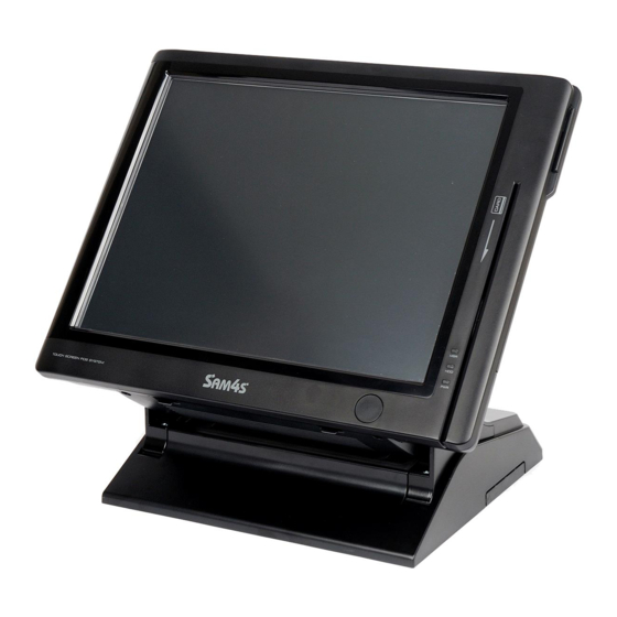
- Page 3 General Specification HOME Dimension(mm) Dimension(mm) 387mm(W) × 278mm(L) × 340mm(H) 387mm(W) × 278mm(L) × 340mm(H) Introductions Weight 5.8 Kg Unpacking Specification CPU : Intel Atom Processor N270 1.6GHz(Onboard) Without FAN Processor Product overview FSB : 533MHz Getting Started Northbridge : Intel 945GSE Chip Sets Southbridge : Intel ICH7M Using this system...
- Page 4 BIOS BIOS AMI(Amerian Megatrends Inc ) BIOS AMI(Amerian Megatrends, Inc.) BIOS 15" TFT LCD, LVDS Interface HOME Resolution & Colors : 1024x768(XGA), 16.2M(RGB) Color Contrast Ratio : 450 : 1 Display Viewing Angle(H-V) : 150˚ / 130˚ (Left : 75˚, Right : 75˚, Up : 70˚, Down : 60˚) Introductions Backlight Type : 2-CCFL BacklightBrightness : 250 cd/㎡...
- Page 5 Features names of Functions and each part HOME Front View Introductions Unpacking Specification Product overview Getting Started Using this system MSR(Magnetic Stripe Reader) Removal and Card (Credit Card, Loyalty Card and so on) Replacement can be recognized for transaction. BIOS Setup Card Recognition Light Exploded View When the card is swiped correctly, the light will be lit.
- Page 6 Bottom View HOME Introductions Unpacking Specification Product overview Getting Started RJ45 LAN Port Using this system Microphone Port Removal and USB Port RJ11 Cash Drawer Port Replacement Customer Display Port Dual Monitor Port BIOS Setup DC Power Supply Port Serial Port Exploded View DC Power Output Port and Replaceable...
- Page 7 Rear View HOME Introductions USB Devices can be used through this Unpacking port, i.e. USB scanner, USB Keyboard, Specification USB Printer, etc. CUSTOMER DISPLAY(CDP) Product overview This shows the amount which Customers have to pay Getting Started SD CARD SLOT SD Card, MMC Card can be used.
-
Page 8: Safety Instructions
Safety Instructions HOME Read the safety instructions carefully and thoroughly. All cautions and warnings on the equipment or user’s manual should be noted. ● Lay this equipment on a stable surface before setting it up. ● Introductions Keep this equipment away from humidity and high temperature. ●... - Page 9 Before connecting Peripherals HOME Connecting Peripherals Introductions Remove Cover Cable Getting Started ❶ In case the screws of Cover Cable are fixed, remove them first. Safety Instructions Removing the Cover Hook of Cover Cable Cable Connecting the External Device Turning the System On and Off Using this system ❷...
- Page 10 Remove Cable Tidy Dummy HOME Remove Cable Tidy Dummy by using (-) shaped driver. Depending upon the places, the system can be used while Cable Tidy Dummy is removed. Introductions Getting Started Safety Instructions Removing the Cover Cable Connecting the External Device Cable Tidy Dummy Turning the System...
- Page 11 Connecting Peripherals The I/O ports on the POS-System allow you to connect peripheral devices. All device listed here are for reference only. HOME Connecting keyboard & mouse Introductions Connect PS/2 type keyboard & mouse. Getting Started Safety Instructions Removing the Cover Cable Connecting the External Device...
- Page 12 Turning the System On and Off Using this system Connecting RJ-11 Cash Drawer Removal and Use RJ-11 port when Cash Drawer is desired & used Replacement (Use SAM4S Cash Drawer). BIOS Setup Exploded View and Replaceable parts How to use PDF e-manual <Cash Drawer>...
- Page 13 Connecting RJ-45 LAN cable HOME RJ-45 LAN or Internet enabled cable can be connected. It supports 10Mbps/100Mbps. Introductions <LAN Hub> Getting Started Safety Instructions Removing the Cover Cable Connecting the External Device Turning the System Connecting USB Device On and Off USB connector is located both the side of LCD panel and the back of the Using this system system so USB devices can be connected at both locations.
- Page 14 Introductions Getting Started Safety Instructions Removing the Cover Note ! Cable QBig Adapter from SAM4S should only be used. Never ▶ Connecting the use the adapter with similar specification or shaped . External Device Turning the System On and Off...
- Page 15 System On/Off HOME System On Introductions After installation of system, proceed to power on the system with following steps. Getting Started Power up the peripherals which are connected with the system. Safety Instructions Removing the Cover Cable Press the power button placed at the left side of system LCD (Open the power button cover and press). Connecting the External Device PWR light is to be lit at the right bottom of the LCD front.
- Page 16 System Off System Off HOME All applications should be off after saving files in the designated place. Introductions Press <Start> button and select 'Turn off Computer' on popup menu. Getting Started Safety Instructions Removing the Cover Cable Connecting the External Device Turning the System On and Off Using this system...
- Page 17 Touch Screen Recalibrate if it is not accurate on touch points. HOME Click the right button of mouse on 'PM' icon of Windows tray icons. Introductions And select 'Control Panel' on popup menu. Getting Started Using this system Touch Screen Backup and Recovery Driver and Utility Check Out Touch Scrrraemememedmdfmdm,drrreen...
- Page 18 bration Touch Screen Calibration HOME Double-click 'PenMount 9000 RS232' on 'Device' Tab. Introductions Getting Started Using this system Touch Screen Backup and Recovery Driver and Utility Dual Monitor Removal and Replacement On 'Calibrate' tab, select the number '25' of Advanced Mode combo-box list if it is possible. BIOS Setup And then click the 'Advanced Calibration' button.
- Page 19 Click the red point about 2 seconds on a calibration screen. Calibration procedure will be proceeded with following messages. HOME Introductions Caution Getting Started Ball point pen or sharpness tools may damage to surface of touch screen. Using this system Touch Screen Backup and Recovery Driver and Utility...
- Page 20 Note ! HOME For using the Touch Screen on Multi-monitor. Check 'Multiple Monitor Support' box on 'Multiple Monitors' tab. Click <Map Touch Screens> button. ❶ ❷ Introductions Getting Started Using this system Touch Screen Backup and Recovery Driver and Utility Dual Monitor Removal and Replacement...
- Page 21 WinClon make the system backup or restored. User can restore the system to ‘the Win&lon (Backup & Recovery) manufactured state’ with WinClon’s initial state image. And user can backup the system with its current state (Create WinClon’s recent state image). HOME Caution Introductions...
- Page 22 5HFRYHU\ RQ :LQGRZV 0RGH Click ‘OK’ button. HOME Introductions Getting Started Using this system User can check the progress. Touch Screen Backup and Recovery Driver and Utility Dual Monitor Removal and Replacement BIOS Setup Exploded View and Replaceable parts Check the message and click ‘Ok’ button, after the restore is successfully How to use PDF completed.
- Page 23 System Backup HOME Press keyboard’s <F11> key when ‘F11 to WinClon’ appears on the screen. Click ‘OK’ button. Introductions Getting Started Using this system Touch Screen Backup and Recovery Driver and Utility Dual Monitor Removal and Replacement BIOS Setup When a below screen appears, press keyboard’s <F10> key. User can check the progress.
- Page 24 Check the message and click ‘Ok’ button, after the backup is successfully completed. The system will be restarted automatically. HOME Introductions Getting Started Note! Using this system Touch Screen Restore Recent State [F2] User can restore the system to ‘the latest backup state’ with ‘WinClon’s recent state’ image Backup and Recovery Driver and Utility Restore Initial State [F3]...
- Page 25 POS Driver and Utility HOME Drivers and utilities are in the folder that the directory is 'C:\Util_Driver\'. Introductions Getting Started Using this system Touch Screen Backup and Recovery Driver and Utility Dual Monitor Removal and Replacement BIOS Setup 'ULYHUV Exploded View Driver installation files Audio, Video and Replaceable LAN, Chipsetand Touch screen.
- Page 26 POS Utility HOME C:\Util_Driver\Utility Introductions Getting Started Using this system Adobe Reader Touch Screen Backup and Recovery MiniPrinter Ellix20 installation file Driver and Utility MS Excel Viewerv Dual Monitor Pos Utility Removal and Replacement BIOS Setup Exploded View and Replaceable parts MSR setup utility How to use PDF...
- Page 27 (C:\Util_Driver\Utility\Pos Utility\OPOS) BIOS Setup The way of installation Exploded View ❶ Run 'SAM4S OPOS Installer.exe'. and Replaceable parts ❷ During OPOS Driver installation, all of components are automatically registered and set up properly for system composition. How to use PDF...
- Page 28 Dual Monitor Additional monitor can be connected to the VGA port at the bottom of QBIG. HOME The system supports 'dual monitors' that is using two monitors for one system. Sub-monitor can be displayed a screen copied a main-monitor's Windows desktop or can be displayed a screen extended Windows desktop.
- Page 29 Select 'Settings' tab on 'Display Properties' dialog. HOME Introductions Getting Started Using this system Touch Screen Backup and Recovery Driver and Utility Dual Monitor Removal and Replacement Click the right button of mouse on the second monitor's indicator and select 'Attached'. BIOS Setup Exploded View and Replaceable...
- Page 30 Check an 'Extend my Windows desktop onto this monitor' and click <Apply> button. HOME Then you can see the extended screen. (If this option is unchecked, the additional monitor displays a screen copied with primary monitor.) Introductions Getting Started Using this system Touch Screen Backup and Recovery Driver and Utility...
- Page 31 Note ! HOME HOME How to check dual monitor's setting If 'dual monitors' doesn't work properly, refer to the following procedure. method1 Check the BIOS Setup 방법1 Introductions Make sure that 'Chipset > North Bridge Chipset Configuration Video Function Configuration Boot Display Device' menu is selected as 'CRT+LVDS'.
- Page 32 System Dismantle & Reassemble HOME HOME Introductions Introductions System Dismantle System Dismantle Getting Started Getting Started Using this system Using this system Make sure the system & peripherals power are off. Removal and Replacement System Disassemble System Disassemble Take off the connector cab from the bottom of system in case it is fixed with screws. System Reassemble System Reassemble Memory Module...
- Page 33 CDP should be rotated as the direction shown in the figure CDP should be separated as the arrow shown and its connector HOME HOME and press ‘PUSH’ area with hands. should be disconnected. Introductions Introductions Getting Started Getting Started Using this system Using this system Removal and Replacement...
- Page 34 Stand can be dismantled as the figure shown. Refer to the figure, unscrew, release lock lever and the system back HOME HOME panel should be taken apart. Introductions Introductions Getting Started Getting Started Using this system Using this system Removal and Replacement System Disassemble System Disassemble...
- Page 35 Upgrading Memory Module Upgrading Memory Module HOME HOME Introductions Introductions In case, the user requires to expand the capacity of system memory, the specification of memory should first be checked. Memory size can be decided a maximum of 2GB, depending upon the specification of its main board. Once the memory is installed, BIOS automatically recognizes Getting Started Getting Started the memory type, capacity and speed.
- Page 36 Replacing Hard Disk Drive HOME HOME Introductions Introductions Getting Started Getting Started 2.5 inch SATA type can only be installed, hence the hard drive type should be checked before purchase. Using this system Using this system Removal and Before system dismantle, save data, turn off the system and all cables & mains power should be disconnected. Replacement System Disassemble System Reassemble...
- Page 37 Remove bracket from the hard disk drive as shown in the figure. HOME HOME Introductions Introductions Getting Started Getting Started Using this system Using this system Remove screws from the hard disk drive as shown in the figure. Removal and Replacement System Disassemble System Reassemble...
- Page 38 Magnetic Stripe Reader(MSR) Removal HOME HOME Introductions Introductions Getting Started Getting Started Remove system back cover (refer to System Dismantle). MSR cable Using this system Using this system Disconnect MSR (Magnetic Stripe Reader) Removal and Replacement cable. System Disassemble Remove 3 screws which hold MSR bracket. System Reassemble Memory Module Remove tape which hold MSR bracket.
- Page 39 Other Main Components Removal HOME HOME Introductions Introductions Getting Started Getting Started Internal Speaker Removal Internal Speaker Removal 내장형 스피커 분리 Using this system Using this system Note ! Removal and Remove system back cover (refer to System Dismantle). When external speaker is connected to be in use, the internal speaker Replacement cable should be disconnected in case the internal speaker does not System Disassemble...
- Page 40 Remove SD card USB board HOME HOME Introductions Introductions Remove system back cover (refer to System Dismantle). Getting Started Getting Started Using this system Using this system Remove screws which hold the bracket. Removal and Replacement System Disassemble System Reassemble Memory Module Hard Disk Drive Magnetic Stripe Reader...
- Page 41 Remove Inverter HOME HOME Introductions Introductions Remove system back cover (refer to System Dismantle). Getting Started Getting Started Using this system Using this system Remove inverter while pressing hook inside the inverter and push forward gently (refer to the figure). Removal and Replacement System Disassemble...
- Page 42 Remove Touch MSR board HOME HOME Introductions Introductions Remove system back cover (refer to System Dismantle). Getting Started Getting Started Using this system Using this system Remove inverter while referring to Remove Inverter. Removal and Replacement Disconnect all cables to Touch MSR board.(Touch, MSR, LED, ETC) System Disassemble System Reassemble Remove Touch MSR board after undoing screws (2EA) which connect to the display bracket.
- Page 43 Remove LED board Remove DSUB board HOME HOME Introductions Introductions Remove system back cover (refer to System Dismantle). Remove system back cover (refer to System Dismantle). Getting Started Getting Started Using this system Using this system Disconnect cables which connect LED board. Disconnect cables which connect DSUB board.
- Page 44 HOME HOME Remove Power board Introductions Introductions Remove system back cover (refer to System Dismantle). Getting Started Getting Started Using this system Using this system Disconnect cables for HDD and remove HDD module (refer to System Dismantle). Removal and Replacement Disconnect cables for speaker and remove SD board (refer to System Dismantle).
- Page 45 Remove Main board Remove Main board HOME HOME Introductions Introductions Remove system back cover (refer to System Dismantle). Getting Started Getting Started Using this system Using this system Remove inverter while referring to Remove Inverter. Removal and Replacement Disconnect all cables to main board. System Disassemble System Reassemble Remove main board after undoing screws to main board and pushing the direction of arrow.
- Page 46 Remove Touch panel HOME HOME Introductions Introductions Getting Started Getting Started Warning Using this system Using this system ※ It appears to happen defectives while disconnecting LCD and touch panel due to dust or mis-handling. Please get correct service from approved service center. Removal and Replacement System Disassemble...
- Page 47 Remove touch panel while holding bracket and lift up the display assembly. HOME HOME Introductions Introductions Getting Started Getting Started Using this system Using this system Hand Hand Removal and Replacement System Disassemble System Reassemble Memory Module Hard Disk Drive Magnetic Stripe Reader (MSR) Internal Speaker...
- Page 48 Disconnect LVDS cable and LCD cable. Unfold disconnected cables, avoid interferences with other cables. HOME HOME Introductions Introductions Getting Started Getting Started LVDS Cable Using this system Using this system Removal and LCD Cable Replacement System Disassemble System Reassemble Memory Module Hard Disk Drive Magnetic Stripe Reader (MSR)
- Page 49 Remove LVDS cable which is connected to LCD after the bracket is lifted while preventing LVDS cable is not put in between. HOME HOME Introductions Introductions Getting Started Getting Started Using this system Using this system Removal and Replacement System Disassemble System Reassemble Memory Module Hard Disk Drive...
- Page 50 Remove Dallas (Option) HOME HOME Introductions Introductions Remove system back cover (refer to System Dismantle). Getting Started Getting Started Using this system Using this system Disconnect cables which connect to its board. Removal and Replacement Remove Dallas holder while rotating it in clock-wise. System Disassemble System Reassemble Memory Module...
- Page 51 System Set up System setup means that the system configuration information is memorized on BIOS Setup Utility It is also saved in a special area of memory called CMOS ROM. HOME Introductions Getting Started Entering the Setup Program Using this system Entering the Setup Program Turn on the system and the system will show 'Press <DEL>...
- Page 52 Initial Setup Screen Initial Setup Screen Initial Setup Screen Initial Setup Screen HOME Initial Setup Screens has menus as Main, Advanced, Boot, Security, Chipset, Power, Exit. Introductions Getting Started Using this system Removal and Replacement BIOS Setup System Set up Exploded View and Replaceable parts...
- Page 53 ← : Select Screen HOME Select menus you want. ↑ , ↓ : Select Item Introductions Move the cursor to select menu or option tab. On focused menu will be changed color to white. Getting Started + , - : Change Option / Field Using this system Use them for setting value.
- Page 54 F7 : Discard Changes HOME Abandon all changes. F8 : Load Failsafe Defaults Introductions In case of improper value input or system error caused by improper configuration setting, you can load default configuration value using this menu. Getting Started F9 : Load Optimal Defaults Using this system Use this menu to load the BIOS default values for the minimal/stable performance for your system to operate.
-
Page 55: Main Menu
Main Menu Use this menu for basic system configuration, such as time. date etc. HOME Introductions Getting Started Using this system Removal and Replacement BIOS Setup System Set up Exploded View and Replaceable parts BIOS Information, Processor, System MemoryDate(mm:dd:yy) How to use PDF These items show the firmware and hardware specifications of your system. - Page 56 Advanced Menu Use this menu to set up the items of special enhanced features. HOME Introductions Getting Started Using this system Removal and Replacement BIOS Setup System Set up Exploded View and Replaceable parts CPU Configuration How to use PDF These items show the advanced specifications of your CPU.
- Page 57 First/Second/Third Boot Device Hardware Health Configuration Hardware Health Configuration HOME Configure or monitor the hardware health. Introductions BACPI Configuration ACPI Configuration ACPI Configuration Getting Started Selects power on state for NumLock Using this system Removal and Replacement USB Configuration BIOS Setup Configure the USB support.
- Page 58 CPU Configuration HOME Introductions MAX CPUID Valve Limit The Max CPUID Value Limit BIOS feature allows you to circumvent problems Getting Started with older OS that don't support the Pentium 4 processor with Hyper-Threading Technology. When enable, the processor will limit the maximum CPUID input Using this system value to 03h when queried, even if the processor supports a higher CPUID input Removal and...
- Page 59 IDE Configuration HOME Introductions ATA/DE Configuration This setting specifies the operation mode of the onboard ATA/IDE controller. Getting Started Legacy IDE Channels Using this system This setting specifies the IDE channels. Removal and Hard Disk Write Protect Replacement This option allows users to write protect boot sector on hard disk to protect against viruses.
- Page 60 Primary IDE Slave HOME Introductions Type Press PgUp/<+> or PgDn/<-> to select [Manual], [None] or [Auto] type. Getting Started Note that the specifications of your drive must match with the drive table. Using this system The hard disk will not work properly if you enter improper information for this category.
- Page 61 Super IO Configuration HOME Introductions Serial Port (1/2/3/4/5/6 Address, Serial Port 1/2/3/4 IRQ) Getting Started Select an address and a corresponding interrupt for the serial port. Using this system Serial Port5 Mode Removal and This setting specifies the serial port5 mode. Replacement Parallel Port Address BIOS Setup...
- Page 62 Hardware Health Configuration HOME Introductions Chassic Intrusion The field enables or disables the feature of recording the chassis intrusion Getting Started status and issuing a warning message if the chassis is once opened. To clear Using this system the warning message, set the field to [Reset]. The setting of the field will automatically return to [Enabled] later.
- Page 63 ACPI Configuration HOME Introductions General ACPI Configuration Suspend mode Getting Started This item specifies the power saving modes for ACPI function. If your OS Using this system system supports ACPI, you can choose to enter the Standby mode in S1 (POS) or S3 (STR) fashion through the setting of this field. Removal and USB Device Wakeup From S3 Replacement...
- Page 64 HOME Introductions USB Configuration LegacyUSB Support Getting Started Set to [Enabled] if your need to use any USB device in the OS that does Using this system not support or have any USB driver installed, such as DOS and SCO Unix. Set to [Disabled] only if you want to use any USB device other than the USB Removal and Port 64/60 Emulation...
- Page 65 Boot Menu Use this menu to specify the priority of boot devices. HOME Introductions Getting Started Using this system Removal and Replacement BIOS Setup System Set up Exploded View and Replaceable Boot Settings Configuration parts Configure settings during system boot. How to use PDF Boot Device Priority e-manual...
- Page 66 Boot Settings Configuration HOME Introductions Quick Boot Enabling this setting will cause the BIOS power-on self test routine Getting Started t o skip some of its tests during bootup for faster system boot. Using this system Quiek Boot This BIOS feature determines if the BIOS should hide the normal POST mes- Removal and sages with the motherboard or system manufacturer's full-screen logo.
- Page 67 HOME Boot Device Priority The items allow you to set the sequence of boot devices/removable drives. Introductions Getting Started Using this system Removal and Replacement Hard Disk Drives BIOS Setup Specifies the boot device priority sequence from available hard drives. System Set up Exploded View and Replaceable...
- Page 68 Security Menu Use this menu to set supervisor and user passwords. HOME Introductions Getting Started Using this system Removal and Replacement BIOS Setup System Set up Exploded View and Replaceable Supervisor Password / Change Supervisor Password parts Supervisor Password controls access to the BIOS Setup utility. These settings allow you to set or change the supervisor password. How to use PDF e-manual User Password / Change User Password...
- Page 69 Chipset Menu This menu controls the advanced features of the onboard Northbridge and Southbridge. HOME Introductions Getting Started Using this system Removal and Replacement BIOS Setup System Set up Exploded View and Replaceable parts How to use PDF e-manual A-19 Content H e l p Printer E x i t...
- Page 70 HOME North Bridge Chipset Configuration Introductions Configure DRAM Timing by SPD Selects whether DRAM timing is controlled by the SPD (Serial Presence Detect) Getting Started EEPROM on the DRAM module. Using this system Boots Graphic Adapter Priority This item specifies which VGA card is your primary graphics adapter. Removal and Replacement Internal Graphics Mode Select...
- Page 71 HOME South Bridge Chipset Configuration South Bridge Chipset Configuration Introductions USB Functions This setting specifies the function of the onboard USB controller. Getting Started USB 2.0 Controller, Audio Controller, PRO-NIC Using this system Controller, SMBUS Controller Removal and These settings enable/disable the specified onboard controllers. Replacement BIOS Setup System Set up...
- Page 72 Power Menu Use this menu to specify your settings for power management. HOME Introductions Getting Started Using this system Removal and Replacement BIOS Setup System Set up Restore on AC Power Loss Exploded View This setting specifies whether your system will reboot after a power failure or interrupt occurs. and Replaceable Available settings are: parts...
- Page 73 Exit Menu When [Enabled], you can set the date and time at which the RTC (real-time clock) alarm awakens the system from Suspend mode. HOME Introductions Getting Started Using this system Removal and Replacement BIOS Setup System Set up Exploded View and Replaceable Save Change s and Exit parts...
- Page 74 HOME Introductions Getting Started Using this system Removal and Replacement BIOS Setup System Set up Exploded View and Replaceable Load Optimal Defaults parts Use this menu to load the BIOS default values for the minimal/stable performance for your system to operate. How to use PDF e-manual Load Failsafe Defaults...
- Page 75 Main Board configuration HOME Major Chipset Intel Atom CPU N270 1.6GHz Introductions Getting Started Using this system Removal and Replacement BIOS Setup Exploded View and Replaceable parts Intel ICH7M (South Bridge) Main Board Configuration SUB Board Configuration & Pin Connection Major Interface Connector Pin Assignments Exploded Views and Parts...
- Page 76 Main Board Connector & Socket Main Board Connector & Socket HOME DC power LED/PWR HDD power SATA Connector Connector Connector Connector Introductions SO-DIMM DDR2 RAM Socket Getting Started Using this system Removal and Replacement BIOS Setup Exploded View and Replaceable parts PCI Slot Main Board Configuration...
- Page 77 SUB Board Configuration & Pin Connection HOME POWER B’ D Introductions DRAWER & POLE(RJ11 &RJ45), [CN15] POLE(RJ45) , [ CN1] Getting Started Using this system DWR#1 COM#5_VSERIAL COM#5_VSERIAL Removal and Replacement COM#5_DSR COM#5_DSR DWR_COMP COM#5_TXD VDRW COM#5_TXD BIOS Setup COM#5_RXD DWR#2 COM#5_RXD...
- Page 78 JOINT B’ D HOME M/B I/F(COM3/4/5/6), [CN1/2/3/4] Introductions Getting Started LPT_/STB LPT_/AFD COM #3/4/5/6_DCD Using this system COM#3/4/5/6_RXD LPT_/D0 LPT_/ERR Removal and COM#3/4/5/6_TXD Replacement LPT_/D1 LPT_/INIT COM#3/4/5/6_DTR BIOS Setup LPT_/D2 LPT_/SLIN Exploded View LPT_/D3 COM#3/4/5/6_DSR and Replaceable LPT_/D4 parts COM#3/4/5/6_RTS LPT_/D5 Main Board Configuration...
- Page 79 TOUCH B’ D HOME POWER B’D I/F(2.0mm), [CN1] INVERTER(12505WS), [CN2] Introductions Getting Started BACKLIT_ADJ COM#6_TXD Using this system COM#6_RTS COM#6_RXD Removal and COM#4_TXD COM#4_RXD Replacement INVT_ON/OFF BACKLIT_ADJ BIOS Setup INVT_ON/OFF USB#5_D(+) USB#5_D(-) Exploded View and Replaceable parts +12V(INVERTER) Main Board Configuration PWRLED(-) HDDLED(-)
- Page 80 TOUCH B’ D HOME 5Wire TOUCH(1.0mm), [CN3/CN4] MSR I/F(12505WS), [CN5] Introductions Getting Started TOUCH_X(-) Using this system TOUCH_X(+) MSR_RCP#3 Removal and TOUCH_SENSE MSR_RDD#3 Replacement TOUCH_Y(+) MSR_RCP#2 BIOS Setup TOUCH_Y(-) MSR_RDD#2 Exploded View MSR_CPD and Replaceable parts Main Board Configuration SUB Board Configuration &...
- Page 81 DSUB LED B’ D B’ D HOME PARALLEL(DSUB 2 5P) , [ CN11] LED(12505WR) , [ CN8] Introductions LPT_/STB LPT_/AFD COM#3/4_DCD MSR LED(G) Getting Started LPT_/D0 LPT_/ERR COM#3/4_RXD MSR LED(GND) Using this system LPT_/D1 LPT_/ERR COM#3/4_TXD...
- Page 82 Major Interface Connector Pin Assignments HOME SYSTEM BLOCK DIAGRAM Introductions Getting Started Atom™N270 IMVP-6 ISL 6261CRZ Using this system Removal and Replacement NORTH BRIDGE BIOS Setup DDR-SODIMM1 SDVO Intel® 945GSE LVD or DVI Exploded View and Replaceable PCI Slot 1 parts Ultra DMA 100 PCI Express x1...
- Page 83 Parallel Communication Port HOME PARALLEL POR T (DSUB25 FEMALE) Introductions Getting Started Using this system Removal and Replacement BIOS Setup Exploded View and Replaceable parts Main Board Configuration SUB Board Configuration & Pin Connection Major Interface Connector Pin Assignments Exploded Views and Parts List How to use PDF e-manual...
- Page 84 Serial Communication(D-SUB9 FEMALE / RJ45) HOME Introductions Getting Started Using this system Removal and Replacement COM1/3/4(DSUB9 M ALE) COM1/3/4(DSUB9 M ALE) COM5(RJ45) BIOS Setup Exploded View and Replaceable VSERIAL parts Main Board Configuration SUB Board Configuration & Pin Connection Major Interface Connector Pin Assignments Exploded Views and Parts...
- Page 85 USB & LAN Port HOME Introductions Getting Started Using this system Removal and Replacement BIOS Setup USB P ORT(TYPE A ) LAN P ORT(RJ45) Exploded View and Replaceable parts Main Board Configuration SUB Board Configuration & Pin Connection Major Interface Connector Pin Assignments Exploded Views and Parts...
- Page 86 DRAWER / DC Power HOME Introductions Getting Started Using this system Removal and Replacement DRAWER P ORT(RJ11) Adapter I n put + 12V BIOS Setup Exploded View and Replaceable parts DRAWER#1 Main Board Configuration DRW_COMP SUB Board Configuration & VDRW(+12V/+24V) Pin Connection Major Interface Connector...
- Page 87 Exploded Views and Parts List HOME Exploded Views Introductions Part List Getting Started PARTS CODE PARTS NAME Q'TY Serviceable REMARK Using this system ASS'Y-MAIN DISPLAY Removal and JK72-20283A PMO-COVER CABLE Replacement JK70-50072A SCREW-TAPTITE JK97-20081A MEA-LEVER HINGE BIOS Setup JK93-00002A PHA-MAIN STAND A5-1 JK72-20304A PMO-STAND Exploded View...
- Page 88 Part List Exploded Views PARTS CODE PARTS NAME Q'TY Serviceable REMARK JK72-20288 PMO-FRONT DISPLAY Buyer SPEC (Silk) HOME JK70-50029A SCREW-TAPPING JK72-20284A PMO-COVER DECO JK72-20294A PMO-LENS LED JK92-01515F PBA-SUB LED B'D JK70-20097A IPR-BRKT MSR Introductions JK70-50072A SCREW-TAPTITE JK70-50072A SCREW-TAPTITE Getting Started JK70-60028A RMO-WATER PROOF JK07-00012A LCD-TFT 3004-000001 UNIT-SPEAKER...
- Page 89 Exploded Views HOME Part List Introductions PARTS CODE PARTS NAME Q'TY Serviceable REMARK Getting Started JK97-20077A MEA-BRKT DISPLAY(M) JK97-20092C MEA-BRKT HINGE(L) Using this system 6001-000665 SCREW-MACHINE JK70-20100A IPR-BRKT SIDE(M) 6001-000665 SCREW-MACHINE Removal and JK70-60029A RMO-RUBBER INSULATOR Replacement JK70-50080A SCREW-MACHINE HAND JK97-00001A UNIT-HDD JK70-20090B IPR-BRKT HDD BIOS Setup...
- Page 90 Part List Exploded views(Option) HOME PARTS CODE PARTS NAME Q'TY Serviceable REMARK QCD-V202 OPTION-CDP(CHARACTER) OPTION QCD-G256 OPTION-CDP(GRAPHIC) JK72-20299A PMO-WINDOW VFD Introductions JK68-40120A LABEL(R)-VFD SHEET JK70-50072A SCREW-TAPTITE Getting Started JK46-00006A UNIT-VFD MODULE(CHARACTER) JK46-00007A UNIT-VFD MODULE(GRAPHIC) JK72-20298A PMO-REAR VFD(M) Using this system JK70-50072A SCREW-TAPTITE JK72-20297A PMO-HOLDER VFD(M) Removal and...
- Page 91 How to use PDF e-manual HOME Introductions Features names and Functions of each part Move to first page Getting Started HOME Front View Introductions Using this system Unpacking Specification Product overview Removal and Getting Started Click these text button Using this system Replacement to move each chapter MSR(Magnetic Stripe Reader)
Need help?
Do you have a question about the SPT-3000 and is the answer not in the manual?
Questions and answers