Advertisement
Advertisement
Table of Contents

Related Manuals for Jandy AquaPure Ei


Summary of Contents for Jandy AquaPure Ei
- Page 1 AquaPure ® Chlorine Generator Workbook...
- Page 3 CONTACT INFORMATION Zodiac Pool Systems 1-800-822-7933 www.Jandy.com Instructor ___________________________________________________ext. _________ Sales person ________________________________________________ ext. ________ ___________________________________________________________ ext. ________ Service Manager _____________________________________________ ext. ________ ____________________________________________________________ext. ________...
-
Page 4: Table Of Contents
TABLE OF CONTENTS SPECIFICATIONS ..................6 COMPONENTS ....................7 LOCATIONS ....................8 PLUMBING ...................... 9,10 ELECTRICAL HIGH VOLTAGE ............... 11-13 SETTING THE CONTROLLER ................ 14 ELECTRICAL LOW VOLTAGE ............... 14,15 TESTING CONNECTION ................. 15 OPERATION ....................16 MANUAL CELL REVERSAL ................17 NO FLOW INDICATOR ................... -
Page 5: Specifications
Specifications: AquaPure Ei Series ® Models: Hard Wired Unit part number – APURE35 Plug-In Unit part number – APURE35PLG Hard Wired Unit - Dual Voltage 240/120 VAC Plug-In Unit – 120 VAC Up to 35,000 gallons Maximum Operating Pressure: 50 psi Input Current @ 240 VAC: ~ 1A Input Current @ 120 VAC: ~ 1.3A Minimum Flow Rate: 40 gpm... -
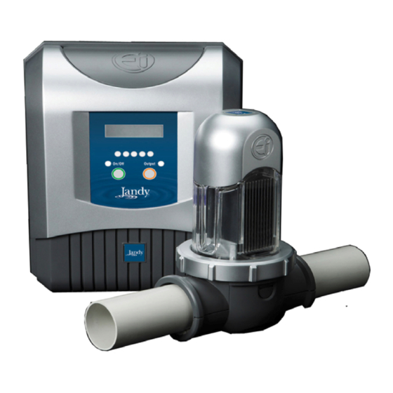
Page 6: Components
Components: Hard Wired Unit Power Pak Flow Salt Flow Salt Cell On /Off Outp ut O n/ O f f O ut put 2 . 5 a m p fu s e s 1 0 0-2 6 5 V AC Fa n Upper Clamp... -
Page 7: Locations
Location: Hard Wired Unit Power Pack and Cell should be no more than 15 feet apart. Fl ow Sal t Flow Sal t Cell should be last item on On/O ff O utp ut O n / O f f O u t p u t equipment pad. -
Page 8: Plumbing
Plumbing: Disassembly Cell clamps Only needed if pipe is 1½ inch Plumbing: Use lower half as a guide to mark location for holes. And here Plumbing: Drill holes with the bit provided. Caution: Do not drill through other side of pipe. And here... - Page 9 Plumbing: Clamp two halves together. Insert Cell and tighten lock nut. Electrical: Remove cover for wiring Electrical: Follow color coding. Run cable down channel. Replace cover when complete.
- Page 10 Electrical: Hard Wired Unit Connect Power Pack to load side of switch, time clock or relay. Fl ow S al t Flow Sal t Ground unit and bond all equipment. n / O f f On/ Off O u t p u t Outp ut Electrical: Plug-In Unit Plug Power Pack into GFCI receptacle.
- Page 11 Electrical: Hard Wired Unit Press in on taps at each side then lift up from bottom to remove gray cover. Flow Salt Fl ow Salt On/Of f Ou tput On/Off Output 2 .5 a mp fu s e s 1 0 0 -2 6 5 VAC Electrical: Hard Wired Unit Remove 4 screws to access terminal bars.
- Page 12 Wiring to controller Carefully lift the cover off WARNING: Be careful not to ‘pull’ the ribbon cable connected from the cover to the power supply Unplug ribbon cable from PCB if necessary Electrical: Hard Wired Unit Wire either 120 or 240 VAC to terminals 2 & 4 of power terminal bar. Unit auto detects voltage.
- Page 13 Some controllers require different interface protocols. The Ei has 3 different modes depending on which controller it will be connected to. The default is set to Jandy L/M. To change: turn the Ei OFF, then press and hold the OUTPUT button for ~6 seconds.
- Page 14 Wiring to Controller Depending on the make of the Controller, make the following wiring connections: Polaris EOS/ Jandy Aqualink Green wire (0V) to ‘0V’ terminal on the Ei Red wire to the (+V) ‘POS’ terminal on the Ei Yellow/White (B) wire to ‘B’ terminal on Ei Black wire (A) to ‘A’...
- Page 15 Operation Salt Ocean water – 36,000 PPM Tear drop – 7,200 PPM AquaPure Ei - 3,500 to 4,000 PPM ® As a general guideline the purer the salt, the better the life and performance of the chlorinator. Calcium and magnesium are the enemies of the cell and cause scaling, poor performance and shortened anode life.
-
Page 16: Operation
Operation Ei SERIES V1.0 AUGUST 2009 Flow S alt Flo w Sa lt On/Off Output On/Off Output When power is first applied to the Ei, it will display the software revision, then default to Off. To turn the Ei on, press the ON button. To increase the Output, press the Output button. - Page 17 The polarity of the Ei can be manually reversed by pressing the ‘hidden’ Hidden polarity button REVERSE button under the Jandy under the Jandy logo. logo for ~4 seconds. The output at the cell will turn off momentarily, the polarity will reverse and the output will turn back on.
- Page 18 No Flow Light “NO FLOW” is displayed when there is insufficient or no water flow through NO FLOW! the cell. There is no chlorine production at this time. Flo w Sa lt The minimum flow rate is 40 gpm. It may also activate if the flow pod is On/ Off Output installed at more than 45°...
- Page 19 Check Salt Light V2.10 • In firmware V2.10 as the pool water temperature or salt level falls the LCD will read “Check Salt or Low Temperature”. • The “Check Salt” light will NOT illuminate until the water temperature is near freezing AND the salt level falls to 3000 ppm or less.
-
Page 20: Check Salt Indicator - V2.0
Check Salt Light V2.10 CHECK SALT OR LOW TEMPERATURE Flow Sa lt Flo w Sa lt On/Off On/Off Output Output • When this message is displayed, the output lights will continue to function and the Ei will try to produce the required amount of chlorine. •... - Page 21 Ei With Aqualink RS The Ei appears as AquaPure MENU in the Aqualink RS menu screen HELP > > PROGRAM > SET TEMP > SET TIME > SET AquaPure BACK DONE DISPLAY LIGHT > > LOCKOUTS > PASSWORD > PROGRAM GROUP >...
- Page 22 LOW SALT on Ei being displayed on the Aqualink RS EQUIPMENT STATUS NOTE: There is no salt sensor – the default for low salt is 2900 AquaPure 15% ppm. The actual salt level may be SALT 2900 PPM BACK CHECK AquaPure lower DONE (Low Salt)
-
Page 23: Error Warning
Error Warning * OUTPUT FAULT * OUTPUT FAULT is displayed when there is a problem with the power supply (service required) Flow S alt On/Off Output Additional Information • All settings are saved using the backup battery as well as EEPROM memory in case the battery runs flat. -
Page 24: Maintenance
Maintenance Weekly Notes:... - Page 25 Warning : Relieve the pressu re with in the system b y opening the pressure relief valve on the pool filter. Notes:...
-
Page 26: Troubleshooting
AquaPure Ei Troubleshooting – Sections references are for the installation manual ®... - Page 27 AquaPure Ei Troubleshooting – Sections references are for the installation manual ®...
- Page 28 AquaPure Ei Troubleshooting – Sections references are for the ins tallation manual ® Notes:...
-
Page 29: Parts And Exploded View
Replacement Parts and Exploded Views Part Number Description R0511400 ELECTRODE, APURE Ei 35, REPLACEMENT KIT R0512100 POWER PCB ASSEMBLY APURE Ei, REPLACEMENT KIT R0512300 CONTROL PCB ASSEMBLY, APURE Ei, REPLACEMENT KIT R0512400 COVER ASSEMBLY, CONTROLLER, APURE Ei, REPLACEMENT KIT R0512500 OUTPUT CABLE ASSEMBLY APURE Ei, REPLACEMENT KIT R0512800 SCREW, PCB MOUNTING, APURE Ei, REPLACEMENT KIT... - Page 30 Replacement Parts and Exploded Views...
- Page 32 AquaPure® Ei Workbook (7-10) AquaPure® Ei Workbook (7-10)
Need help?
Do you have a question about the AquaPure Ei and is the answer not in the manual?
Questions and answers