Table of Contents
Advertisement
Quick Links
Advertisement
Table of Contents

Related Manuals for Riello Condexa Pro2 EVO Series


Summary of Contents for Riello Condexa Pro2 EVO Series
- Page 1 Condexa Pro2 EVO EN INSTALLATION INSTRUCTIONS...
-
Page 2: Table Of Contents
RANGE INDEX 1 GENERAL INFORMATION . . . . . . . . . . . . . . . . . . . . . . . . . . . . 3 MODEL CODE 2 WARNINGS . -
Page 3: General Information
GENERAL INFORMATION GENERAL INFORMATION been connected up to the water, gas and electricity mains so as to be able to activate the frost protection systems de- Dear Customer, scribed in paragraph “6.2.6 Frost protection” page 14 congratulations on your choice and thank you for placing your confidence in our products. -
Page 4: Technical Features
TECHNICAL FEATURES It is forbidden to obstruct the condensate drain. It is forbidden to pull, detach, twist the wiring coming out of the heating unit, even if unplugged from the power supply. It is forbidden to obstruct or reduce the size of air vents. It is forbidden to expose the boiler to atmospheric agents (if it is not a specific unit for outdoors). -
Page 5: Components
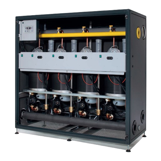
TECHNICAL FEATURES 3.4 Components elements and the whole battery. The combustion system includes: Condexa Pro2 EVO is made up of a series of Thermal Units in- − gas electro valve in B+C class for each thermal element, stalled in battery placed inside a metal casing. with gas flux pneumatic compensation according to the Each thermal unit is connected to the system in parallel posi- inlet air flow ( air/gas 1:1 ratio);... - Page 6 TECHNICAL FEATURES DIMENSIONS AND CONNECTION POSITIONS CONDEXA PRO2 150 EVO IN CONDEXA PRO2 225 EVO IN CONDEXA PRO2 300 EVO IN 1700 Figure 3 SYSTEM COMPONENTS Frame 13 Ignition electrode Control panel 14 Automatic vent valve Exchanger 15 Safety thermostat Air inlet pipe 16 Gas cock 17 Venturi tubes...
-
Page 7: Installation
INSTALLATION 4 INSTALLATION − Power type from mains − Rated heat capacity (Qn) Condexa Pro2 EVO heating units must be installed in con- − Rated working power (Pn) − Efficiency according to 92/42/EEC Directive (η) formity to the latest provisions of the law and standards in force concerning heating units, condensing boilers and/or −... -
Page 8: Water Connections
INSTALLATION 4.3 Water connections If there are more than one boiler, they must all be put into service either contemporarily or with a very low rotation Condexa Pro2 EVO thermal modules are made up of 2, 3 or 4 time during the initial period of service, so as to evenly dis- thermal elements which are common to all the boilers belong- tribute the limited quantity of initial lime-scale. -
Page 9: Positioning And Preparation For Installation
INSTALLATION latter from becoming oxidized), it is necessary: There is generally no need to take any special precautions for − for the expansion system to be a closed vessel type, cor- draining condensate. rectly scaled and with the correct pre-loading pressure We advise using plastic (PP) piping for building the condensate (to be regularly checked);... -
Page 10: Water Circuit
The chimney should be as straight as possible, sealed and iso- lated. Should not have occlusions or narrowing. The overall potential of thermal groups Condexa Pro2 EVO Series is more than 35 kW, so they can be installed only in rooms that have venting opening to the outside according to actual law (italian D.M. -
Page 11: Installation Diagrams
INSTALLATION DIAGRAMS 5 INSTALLATION DIAGRAMS An installation diagram must generally be adapted to the man- ufacturing characteristics of the relevant heating unit, with the purpose of exploiting the boiler potentials to the full and main- tain the entire installation efficient for as long as possible. The “Figure 9”... -
Page 12: Electrical System
It is best to install a differential circuit-breaker switch along the line supplying power to the boiler. When installing a single Condexa Pro2 EVO Series the connection Adapters, multiple sockets, extensions to feed the appliance must be made in accordance with current regulations regarding are not allowed. -
Page 13: Connection To Pumps
ELECTRICAL SYSTEM 6.2.3 Connection to pumps For example, by connecting the low temperature circulator to a timer and/or external room thermostat the electrical instal- Condexa Pro2 EVO regulation system includes the simultaneous lation will be the one shown in “Figure 11”. . By this system is management of up to three circulators. -
Page 14: Connection To Room Thermostats (On/Off)
ELECTRICAL SYSTEM 6.2.4 Connection to room thermostats (on/off) Power and fuel gas supply must be activated and the water system at a correct pressure for the frost protection system Connect up the high temperature system room thermostat to to function. terminals 9. -
Page 15: Position Of The Flow Probe
ELECTRICAL SYSTEM PUMP TO MAIN POLO GROUND PHASE NEUTRAL FUSE 4A GAS VALVE LAST SLAVE CONNECTOR J14 LIMIT THERMOSTAT Figure 13 PRESSURE SWITCH BLOWN (+ ) INPUT SENSOR HALL POWER SENSOR HALL COMMON SENSOR HALL BLOWN (-) NTC - FLOW NTC - RETURN SET J17 SWITCHES ON THE OFF POSITION... -
Page 16: First Operating
FIRST OPERATING 7 FIRST OPERATING To complete the start-up of the boiler, the following operations are necessary, that should only be performed by an authorized Service − verification of the installation; − combustion analysis. 7.1 Gas valve calibration Gas valve calibration jobs must be done by the Technical As- sistance Service authorized by only. -
Page 17: Use And Adjustment
USE AND ADJUSTMENT 8 USE AND ADJUSTMENT 8.1 Control panel: description The digital Master control panel of the Condexa Pro2 EVO is locat- ed in the external cabinet. It is possible to operate on the master contro.l panel opening the cover with the plexiglass window. The various buttons on it allow you to perform a variety of func- tions ranging from simple monitoring of the main parameters to the system configuretion of the device depending on the type of... -
Page 18: Display Mode
USE AND ADJUSTMENT 8.2 Display mode The red (error) LED turns on in the case of faults that involve the permanent block of a heating element (normal operation can be reset by pressing the Master or Slave reset button). The green (on) LED indicates the presence of the electric power supply. The 3 digits with seven segments display the system statuses: SYSTEM STATUS DISPLAY... -
Page 19: User Parameter Change
USE AND ADJUSTMENT 8.4 Changing the user parameters Pressing displays the following values in succession: − manifold delivery temperature T1 − DHW temperature T3 − low temperature circuit delivery temperature T6. To change the relative setpoints: − press the “Set/esc” button: the relative value will appear, the two digits on the right will flash −... -
Page 20: Installer Programming Mode
USE AND ADJUSTMENT The following values for each single unit can be visualized with POS. DIMENSIONS DISPLAY Flow temperature (e.g. 70° C) Return temperature (e.g. 50° C) Exhaust flue temperature (e.g. 60° C) Ionization current (index from 0 to 99). E.g. -
Page 21: Test Mode
USE AND ADJUSTMENT 8.7 Test mode In test mode it is possible to generate a high temperature heating demand at maximum power and at minimum power. All system fans must be activated. If the installer turns off the switch for some Slaves, the others, connected to the Master, must continue to operate. -
Page 22: Adjusting The Functional Parameters
ADJUSTING THE FUNCTIONAL PARAMETERS 9 ADJUSTING THE FUNCTIONAL PARAMETERS 2 Setpoint_T_CH_Low Low temperature circuit setpoint (parameter 3) The heating functions can be set for the high temperature, low If the “fixed point” operating mode is set (par. 22=CH_type_ temperature and DHW circuits based on the system require- low=0), it is the target temperature. - Page 23 ADJUSTING THE FUNCTIONAL PARAMETERS 2 DHW_Type 21≠0, the high temperature thermostat contact is ignored and a Boiler type (parameter 6) heat demand is present for the high temperature circuit when: 0 = No DHW service Manifold temperature <=Setpoint – ignition hysteresis 1 = Quick exchanger with sensor 2 = Boiler with sensor The heat demand stops when:...
- Page 24 ADJUSTING THE FUNCTIONAL PARAMETERS tion_low) if the contact is open. 6 Power_control_mode PERATION WITH CLIMATIC CONTROL, PAR. 22=1 Cascading management (parameter 33) If the low temperature circuit attenuation is equal to 0 , Atten- To manage the power delivered by the system, two cascading uation_low=Par.
- Page 25 ADJUSTING THE FUNCTIONAL PARAMETERS Low load The low load function prevents burner ignition and shut off in the case of a low heat demand. The conditions for low load op- eration activation is controlled in every Slave card that sends the function activation request to the Master.
- Page 26 ADJUSTING THE FUNCTIONAL PARAMETERS − Delivery temp. > Setpoint_ch_high (Par.1) + Ch_high_hist_ Safety functions of the Slave cards off (Par.20) − (Delivery temp. > Setpoint_ch_low (Par.3) + Ch_low_hist_ If the delivery temperature > 90°C for 5s, the slave card is blocked off (Par.27) (no.
-
Page 27: List Of Parameters
LIST OF PARAMETERS 10 LIST OF PARAMETERS The list of parameters for Condexa Pro2 EVO is given here below. The user may only alter the first three parameters, whilst the Technical Assistance Service must be called in for the others. User parameters Factory set- Parameter name... - Page 28 LIST OF PARAMETERS Factory set- Parameter name Lower limit Upper limit Description ting CH1 max. Temp. 80°C 10°C 80°C Max. settable value for high system CH1 min. Temp. 50°C 10°C Par.1 Min temp. value high system (at max. external T.). Burner re-ignites after said differential.
-
Page 29: Error List
ERROR LIST 11 ERROR LIST A and E type errors possibly encountered with Condexa Pro2 EVO are given in the tables below. In this sense it should be specified that an E-type error (volatile error) is a fault which automatically disappears as soon as the fault is resolved;... - Page 30 ERROR LIST No. on the PC Cause Troubleshooting Internal error Replace the Slave card. Internal software error Press the rest button. Internal error Replace the Slave card. The limit thermostat contact is open with Connector disconnected or defective. the burner off Limit thermostat defective.
-
Page 31: Wiring Diagrams
WIRING DIAGRAMS 12 WIRING DIAGRAMS Polo principale di terra GROUND 230V~50Hz NEUTRAL PHASE SHEATHED JUNCTION J10 6 J11 7 Pump J10 5 J11 14 J10 4 J11 6 Pump J10 3 J11 13 J10 2 J11 5 Pump 3 J10 1 J11 12 Circ. - Page 32 WIRING DIAGRAMS PUMP TO MAIN TO MAIN POLO GROUND POLO GROUND PHASE PHASE NEUTRAL NEUTRAL FUSE 4A Slave n°2-3-4 Slave n°1 GAS VALVE LIMIT THERMOSTAT PRESSURE SWITCH BLOWN (+ INPUT SENSOR HALL POWER SENSOR HALL COMMON SENSOR HALL BLOWN (-) NTC - FLOW NTC - RETURN NTC - SMOKE...
-
Page 33: Technical Data
TECHNICAL DATA 13 TECHNICAL DATA Condexa Pro2 Evo IN-EXT Detail U.M. Certifications Boiler typology B23, B53, B53p, C13, C33, C53, C63 Overall dimensions and Connections Height x Width x Depth 1690x900x750 1690x1700x750 Loadless boiler weight Water capacity Diameter Water connections 2”... - Page 34 WATER IN CENTRAL HEATING SYSTEMS Detail U.M. Maximum rated heat input Minimum rated heat input 16,6 16,6 Domestic hot water maximum rated thermal input (80-60) Domestic hot water minimum rated thermal input (80-60) PARAMETER Seasonal heating energy efficiency class Water heating energy efficiency class Rated input Prated 146,6...
- Page 35 WATER IN CENTRAL HEATING SYSTEMS 2.2 Reconditioning old central heating systems STEEL BOILERS with furnace power < 150 kW IIf a boiler has to be replaced, do not refill the entire central Initial filling Regular service heating circuit if the quality of water in it conforms to require- water water (*) ments.
- Page 36 RIELLO S.p.A. 37045 Legnago (VR) Tel. 0442630111 - Fax 044222378 - www.riello.it As part of the company’s ongoing commitment to perfecting its range of products, the appearance, dimensions, technical data, equipment and accessories may be subject to variation.
Need help?
Do you have a question about the Condexa Pro2 EVO Series and is the answer not in the manual?
Questions and answers