Table of Contents
Advertisement
Quick Links
VISION PLUS
High efficiency combi boiler
Users Instructions
Installation &
Servicing
Instructions
VISION PLUS 35 C G.C. N° 47-364-54
VISION PLUS 40 C G.C. N° 47-364-55
THESE INSTRUCTIONS
TO BE RETAINED
BY USER
Vokèra is a licensed member of the Benchmark scheme
which aims to improve the standards of installation and
commissioning of domestic hot water systems in the UK.
Advertisement
Table of Contents

Related Manuals for Riello Vokera VISION PLUS 35 C G. C.


Summary of Contents for Riello Vokera VISION PLUS 35 C G. C.
- Page 1 VISION PLUS High efficiency combi boiler Users Instructions Installation & Servicing Instructions VISION PLUS 35 C G.C. N° 47-364-54 VISION PLUS 40 C G.C. N° 47-364-55 THESE INSTRUCTIONS TO BE RETAINED BY USER Vokèra is a licensed member of the Benchmark scheme which aims to improve the standards of installation and commissioning of domestic hot water systems in the UK.
-
Page 2: Table Of Contents
1.1A GAS APPLIANCES SETTINGS MENU TREE STRUCTURE 1.2A ELECTRICAL SUPPLY STARTING THE BOILER 1.3A WARRANTY REGISTRATION BOILER CONFIGURATION FIRST COMMISSIONING 1.4A APPLIANCE COMMISSIONING CHECKLIST (UK ONLY) VENT CYCLE 1.5A HOW DOES IT WORK? OPERATING STATUS 1.6A DIMENSION 1.7A CLEARANCES REQUIRED COMMISSIONING 1.8A FROST PROTECTION SYSTEM... -
Page 3: A Gas Appliances
USERS INSTRUCTIONS INTRODUCTION Dear Customer Your Vokèra VISION PLUS boiler has been designed to meet and exceed the very latest standards in gas central heating technology, and if cared for, will give years of reliable use and efficiency. Please therefore take some time to read these instructions carefully. Do’s and Don’t’s - Do ensure that the system pressure is periodically checked - Do ensure that the boiler should not be used by children or unassisted disabled people... -
Page 4: A Control Panel
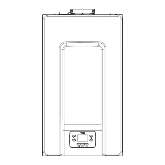
1.9A CONTROL PANEL Indicates the connection to a remote device (OT or Your boiler is equipped with a large LCD display that indicates the RS485) appliance operating status. Indicates the connection to a WIFI device Indicates the presence of an outdoor temperature sensor Indicates the activation of special domestic hot water functions or the presence of a system for managing... -
Page 5: Getting Started
2A GETTING STARTED 2.1A PARAMETERS ACCESS 2.2A PROGRAMMING THE BOILER Pressing the MENU key for at least 2 sec provides access to the Ensure the gas and electrical supplies to the appliance are P1 menu, allowing the parameters to be programmed. switched on. -
Page 6: A Operating Mode
In this status the boiler activates the traditional function of Vent cycle just domestic hot water, the interface normally displays the Whenever the electrical supply to the appliance has been delivery temperature. In the event of a domestic hot water pick disrupted (OFF) and then restored (ON), it will enter a 4-min up, the display shows the temperature of the domestic hot vent cycle. -
Page 7: A Otbus Remote Control Connection
2.3.5A ADJUSTING THE HEATING WATER 2.3.8A RESET FUNCTION TEMPERATURE WITH AN OUTDOOR The “RESET” icon comes on when there is an alarm that TEMPERATURE SENSOR CONNECTED requires a manual reset by the user (for example flame If an outdoor temperature sensor is installed and thermoregu- lockout). -
Page 8: A Boiler Fault Codes
2.5A BOILER FAULT CODES ERROR DESCRIPTION OF ALARM FAULT CODE TYPE flame lockout/ E010 condensate discharge blockage definitive fumes discharge alarm/air intake obstructed E011 extraneous flame transitional E020 limit thermostat definitive E030 fan fault definitive E040 pressure transducer – load system definitive E041 water transducer –... -
Page 9: How To
3A HOW TO... 3.1A HOW TO TOP-UP THE SYSTEM While the electrical supply and the fuel supply remain active, the boiler is protected by the systems: PRESSURE - heating anti-freeze: this function is activated if the temperature The system pressure must be checked periodically to ensure measured by the flow sensor drops below 5°C. -
Page 10: What If
3.7A INTERFACE STAND BY Usually, when there are no faults or heat requests, the display always shows the temperature measured by the flow sensor. If within 10 seconds there is no heat request without any key being pressed the interface goes into stand by. The display shows the current time, the two points separating the time from the minutes blink with a frequency of 0.5sec ON and 0.5sec OFF, while the status icons will be active if necessary:... -
Page 11: Introduction
INSTALLATION AND SERVICING INSTRUCTIONS INTRODUCTION All installers are asked to follow the Benchmark Scheme by VISION PLUS boiler complies with basic requirements of the adhering to the Code of Practise, which can be obtained from following Directives: www.centralheating.co.uk. - Regulation (EU) 2016/426; The VISION PLUS is comprised of a 7-model range of high - Yield directive: Article 7(2) and Annex III of directive 92/42/ efficiency appliances, with outputs ranging from 20kW to 40kW. -
Page 12: Design Principles And Operating Sequence
DESIGN PRINCIPLES AND OPERATING SEQUENCE PRINCIPLE COMPONENTS Thereafter, the boiler’s output will either be increase to maximum or modulate to suit the set requirement. When the appliance • A fully integrated electronic control board featuring electronic reaches the desired temperature the burner will shut down and temperature control, anti-cycle control, pump over-run, self- the boiler will perform a three-minute anti-cycle (timer delay). -
Page 13: Technical Data
TECHNICAL DATA Central Heating VISION PLUS 35C VISION PLUS 40C Heat input (kW) 30.00 30.00 Maximum heat output (kW) 60/80°C 29.25 29.25 Minimum heat output (kW) 60/80°C 4.65 4.65 Maximum heat output (kW) 30/50°C 32.25 32.25 Minimum heat output (kW) 30/50°C 5.08 5.08 Minimum working pressure... - Page 14 VISION PLUS 35C Seasonal space heating energy efficiency class Water heating energy efficiency class Parameter Symbol Value Unit Parameter Symbol Value Unit Seasonal space heating Rated heat output Prated ηs energy efficiency For boiler space heaters and boiler combination heaters: useful heat output For boiler space heaters and boiler combination heaters: useful efficiency At rated heat output and high- At rated heat output and high-...
-
Page 15: Pump Duty
PUMP DUTY Fig. 4 shows the flow-rate available – after allowing for pressure loss through the appliance – for system requirements. When using this graph, apply only the pressure loss of the system. Fig. 5 1000 1100 1200 1300 Flow rate (l/h) HOW TO FREE THE PUMP To “release”... -
Page 16: General Requirements (Uk)
GENERAL REQUIREMENTS (UK) This appliance must be installed by a competent person in ac- If the gas supply serves more than one appliance, it must be cordance with the Gas Safety (Installation & Use) Regulations. ensured that an adequate supply is maintained to each appli- ance when they are in use at the same time. -
Page 17: Electrical Supply
3.6.5 EXPANSION VESSEL 3.10 WATER TREATMENT The appliance has an integral expansion vessel to accom- Vokèra recommend that an inhibitor - suitable for use with modate the increased volume of water when the system is stainless-steel heat exchangers - is used to protect the boiler heated. -
Page 18: E Gas Supply
Where the installation of the appliance will be in an unusual 3.6.6E FILLING POINT location special procedures may be necessary, refer to I.S. 813 A method for initial filling of the system and replacing water lost for detailed guidance on this aspect. during servicing etc. -
Page 19: Installation
INSTALLATION NOTE Horizontal flue terminals and accessories Please refer to 3 - 3E and use the appropriate PPE when Part No. Description Length carrying out any of the actions or procedures contained within 20122759 Standard horizontal flue Kit 900mm this section. 20122761 Telescopic flue kit 700mm... - Page 20 Fit the appropriate flashing to the roof and insert the vertical flue Fig. 13 terminal through the flashing from outside, ensuring that the collar of the terminal is located over the outlet of the flashing. The fixing holes for the appliance wall mounting bracket should now be drilled and plugged.
-
Page 21: Connecting The Gas And Water ("Fig. 18")
IMPORTANT C/H return Fig. 18 Cold water inlet The vertical flue terminal is 1.0 metre in length and cannot be valve cock stopcock cut; therefore it may be necessary to adjust the height of the appliance to suit or use a suitable extension. Safety valve Hot water outlet outlet... -
Page 22: Instruction For Condensation Exhaust Connection
INSTRUCTION FOR CONDENSATION Insert the supplied 3-AMP fuse into the fused isolator or fused plug. EXHAUST CONNECTION Should the fly-lead be unsuitable, refer to 4.8 for details on how to connect the electrical supply directly to the boiler. This product is designed to prevent the escape of gaseous The electrical supply must be as specified in section 3/3E. -
Page 23: Operation
OPERATION CONTROL PANEL NOTE Please refer to 3 - 3E and use the appropriate PPE when Your boiler is equipped with a large LCD display that indicates carrying out any of the actions or procedures contained within the appliance operating status. this section. -
Page 24: Settings Menu Tree Structure
When the icon is active, it is possible to navigate the menu or raise the value of the selected parameter When the icon is active, it is possible to navigate the menu or lower the value of the selected parameter The icon comes on if central heating is active, it blinks if a heating request is in progress The icon comes on if domestic hot water is active, it blinks... -
Page 25: Starting The Boiler
Scrolling message Password Value set Personalised Menu Parameters Value only if parameter P1.05 = 1 level in the factory values P4.15 MAIN ZONE TYPE 0 / 1 INSTALLER AT: MIN CH SET - 80.5 80.5 P4.16 MAX CH SET INSTALLER BT: MIN CH SET - 45.0 AT: 40 - MAX CH SET P4.17... -
Page 26: Boiler Configuration
Each time that the boiler is powered a vent cycle is carried out P3.06 lasting 4 min. The display shows the message -AIR lighting up This parameter allows you to change the minimum number of the fan's rpm. the icon RESET. P3.07 This parameter allows you to change the maximum number of the fan's rpm. - Page 27 P4.12 P4.27 This parameter allows you to configure the system to manage a mixing valve When P4.12 = 1, this parameter allows you to the setpoint value of and an additional pump on the main heating system (the use of the BE16 heating zone 1.
-
Page 28: First Commissioning
FIRST COMMISSIONING Heating REQUEST, the radiator icon blinks: Ensure that steps 6.1 through to 6.6 have been completed be- fore supplying the gas and electrical supply to the appliance. ƒ Position the system’s master switch to the “on” position. ƒ Open the gas tap to allow fuel to flow. 5.8.2 SUMMER MODE ƒ... - Page 29 The level bars beside the heating icon show the setpoint value 5.8.7 SAFETY STOP set with respect to the operating range: If there are ignition faults or boiler operation malfunctions, - four bars on = max setpoint carry out a “SAFETY STOP”. On the display, in addition to the fault code, the icon is also displayed, which blinks with a - one bar on = min setpoint...
- Page 30 5.8.10 SPECIAL DOMESTIC HOT WATER FUNCTIONS The boiler has special functions more a more efficient management of the domestic hot water when there a high domestic hot water temperature input. By programming the P5.11 parameter it is possible to activate the following function, for more information about setting the parameter see the relative paragraph “5.5 Boiler configuration”.
-
Page 31: Commissioning
COMMISSIONING PRE-OPERATION CHECKS NOTE Please refer to 3 - 3E and use the appropriate PPE when Before attempting the initial lighting of the appliance, the following carrying out any of the actions or procedures contained within checks must be carried out: this section. -
Page 32: Regulating The Central Heating System
to the maximum of 1.5 bar total). N.B. The safety valve is set Complete details of the boiler, controls, installation and com- to lift at 3 bar/30 metres/45 psig. To lower the system pressure missioning in the Benchmark checklist at the back of this to the required value, drain off some water from the appliance book. -
Page 33: Cleaning The Primary Heat Exchanger
CLEANING THE PRIMARY HEAT siphon must be filled with water before starting the boiler again. At the end of the maintenance operations on the EXCHANGER siphon and the SRD device we recommend run the boiler - Switch off the electrical supply by turning the system’s main in condensate regime for a few minutes and check there switch to “Off”. -
Page 34: Casing Removal (Fig. 26)
in section 4.7 and drain the water content from the appliance via the drain valve. Ensure some water absorbent cloths are available to catch any residual water that may drip from the appliance or removed component. Undertake a complete com- missioning check as detailed in section 6, after replacing any component. -
Page 35: Gas Valve (Fig. 31)
7.19 GAS VALVE (FIG. 31) Carry out component removal procedure as described in 7.9. The gas valve must be changed as complete unit. Disconnect the electrical plug and leads from the gas valve, slacken and unscrew gas valve inlet and outlet connections. Please note, the sealing washers (Q) must be discarded and replaced with new sealing washers. -
Page 36: Combustion Unit (Fig. 36)
7.22.2 TRANSFORMER (FIG. 35) Carry out component removal procedure as described in 7.9. Unscrew the screw that fixs the transformer and remove it. 7.23 COMBUSTION UNIT (Fig. 36) Refer to 7.9 and carry out the component removal procedure - Remove the casing as indicated in paragraph 7.10. - Disconnect the electrode connection cables. -
Page 37: Removing The Siphon (Fig. 39)
7.26 REMOVING THE SIPHON (FIG. 39) Refer to 7.9 and carry out the component removal procedure - Take out the condensate collection pipe - Unscrew the SRD device - Unscrew the screw (A) and remove the plate (B) - Take out the inside part (C) of the siphon. Once the operations are finished, put back the components in the reverse order to that described, checking the gasket and sealing OR are correctly positioned. -
Page 38: Checks, Adjustments And Fault Finding
CHECKS, ADJUSTMENTS AND FAULT FINDING N OTE When the temperature of the flow sensor falls below the set point (- hysterisis), the burner will re-light. Please refer to 3 - 3E and use the appropriate PPE when carrying out any of the actions or procedures contained within NOTE this section. -
Page 39: External Faults
ƒ The display shows for 10 sec. the number of revs set, together with the rpm icon. ƒ The boiler will function at min power. ƒ Check on the analyser that the min CO2 complies with what indicated in the table, if data are different proceed with the calibration of the gas valve - see paragraph “8.10 Gas valve calibration”... -
Page 40: Electrical Checks
ELECTRICAL CHECKS COMPONENT VALUES & CHARACTERISTICS Any electrical checks must be carried out by a suitably quali- fied person. COMPONENT VALUE 230Vac 8.6.1 EARTH CONTINUITY TEST Pump 230Vac Isolate the appliance from the electrical supply, and using a Valve actuator 230Vac suitable multi-meter carry out a resistance test. - Page 41 Depending on plant engineering requirements or regional table 2 flue gas emission limits it is, however, possible to modify this MIN RPM FAN value, referring to the following graphs. NATURAL GAS SPEED (G20) (G31) HTG curve - VISION PLUS 1.700 2.000 1.700 2.000...
- Page 42 SELECTING THE THERMOREGULATION CURVE (PA- NIGHT COMPENSATION (PARAMETER P4.20) RAMETER P4.19) If a ROOM THERMOSTAT is connected to a programming The thermoregulation curve for heating maintains a theoretical timer, from the menu P4 parameter P4.20 the night temperature of 20°C indoors, when the outdoor temperature is compensation can be enabled.
- Page 43 FOR FAULT E091 If the reset attempts do not activate the boiler, contact The boiler has an auto-diagnostic system which, based on your installer or Vokera Ltd. the total number of hours in certain operating conditions, can FOR FAULT E041 signal the need to clean the primary exchanger (alarm code If the pressure drops below the safety threshold of 0.3 bar E091).
- Page 44 8.15 INFO MENU Pressing key 3 on the display screen displays a list of informa- tion regarding the operation of the boiler listed by parameter name and value. Passing from the display of one parameter to the next takes place by pressing respectively the keys Pressing the key allows the selected parameter to be displayed;...
- Page 45 8.16 EMBEDDED CLOCK Setting the time bands The display shows TIME ON, press to set the ignition time, The appliance incorporates an embedded clock that can be with change the time and confirm with enabled and used to insert ON/OFF time periods for boiler The display shows TIME OFF, press to set the switching operation;...
- Page 46 WIRING DIAGRAMS NOTE Please refer to 3 - 3E and use the appropriate PPE when carrying out any of the actions or procedures contained within this section. EXTERNAL WIRING The appliance comes with a factory fitted (TA) link to allow basic operation of the boiler via the mode selector switch.
- Page 47 FUNCTIONAL DIAGRAM Fig. 45...
- Page 48 10 LPG INSTRUCTIONS 10.1 RELATED DOCUMENTS BS 5440 PARTS 1 & 2 FLUES & VENTILATION REQUIREMENTS BS 5449 PART 1 FORCED CIRCULATION OF HOT WATER SYSTEMS BS 5482 PART 1 DOMESTIC BUTANE & PROPANE GAS BURNERS IN PERMAMENT DWELLINGS BS 5546 INSTALLATION OF GAS HOT WATER SUPPLIES FOR DOMESTIC PURPOSES BS 6798 INSTALLATION OF BOILERS OF RATED NOT EXCEEDING 60kW...
- Page 49 COMMISSIONING: CO AND COMBUSTION RATIO CHECK BEFORE CO AND COMBUSTION RATIO CHECK NOTE The installation instructions should have been followed, gas type verified and gas supply pressure/rate checked as required The air/gas ratio valve is factory-set and must not be prior to commissioning.
- Page 50 Benchmark Commissioning & Warranty Validation Service Record It is a requirement that the boiler is installed and commissioned to the manufacturers’ To instigate the boiler warranty the boiler needs to be registered with the manufacturer within one month of the installation. The warranty rests with the end-user (consumer), and they should be made aware it is ultimately their responsibility to register with the manufacturer, within the allotted time period.
- Page 51 GAS BOILER SYSTEM COMMISSIONING CHECKLIST & WARRANTY VALIDATION RECORD Address: Boiler make and model: Boiler serial number: Commissioned by (PRINT NAME): Gas Safe registration number: Company name: Telephone number: Company email: Company address: Commissioning date: Heating and hot water system complies with the appropriate Building Regulations? Time, temperature control and boiler interlock provided for central heating and hot water Boiler Plus requirements (tick the appropriate box(s)) Weather compensation...
- Page 52 SERVICE & INTERIM BOILER WORK RECORD It is recommended that your boiler and heating system are regularly serviced and maintained, in line with manufacturers’ instructions, and that the appropriate service / interim work record is completed. Service provider When completing a service record (as below), please ensure you have carried out the service as described in the manufacturers’ instructions. Always use the SERVICE/INTERIM WORK ON BOILER SERVICE/INTERIM WORK ON BOILER Date:...
- Page 53 SERVICE & INTERIM BOILER WORK RECORD It is recommended that your boiler and heating system are regularly serviced and maintained, in line with manufacturers’ instructions, and that the appropriate service / interim work record is completed. Service provider When completing a service record (as below), please ensure you have carried out the service as described in the manufacturers’ instructions. Always use the SERVICE/INTERIM WORK ON BOILER SERVICE/INTERIM WORK ON BOILER Date:...
- Page 54 Vokèra Warranty Terms and Conditions Vokèra Ltd offer customers the comfort of a parts and labour warranty repair service subject to the following terms and conditions. Vokèra Ltd only obligation under the guarantee shall be to repair or replace the faulty appliance at Vokèra Ltd discretion.
- Page 55 d. To de-scaling or other work required as a result of hard water scale deposits or from damage caused by aggressive water or sludge resulting from corrosion. Indications that such work may be required include a noisy boiler, cold spots on radiators, sludge in pipes and poor circulation of the central heating system. e.
- Page 59 RANGE RATED - EN 15502 The max CH input of this boiler has been adjusted to_____ kW, equivalent to _____ rpm max CH fan speed. Date___/____/____ Signature _____________________ Boiler serial number _____________________ Registered address: Vokèra Ltd Borderlake House Unit 7 Riverside Industrial Estate London Colney Herts AL2 1HG www.vokera.co.uk...
Need help?
Do you have a question about the Vokera VISION PLUS 35 C G. C. and is the answer not in the manual?
Questions and answers