Table of Contents
Advertisement
Quick Links
Advertisement
Table of Contents

Subscribe to Our Youtube Channel
Related Manuals for College Park LTI BOSTON


Summary of Contents for College Park LTI BOSTON
- Page 1 BOSTON ® DIGITAL C L I N I C I A N S M A N U A L...
- Page 2 BOSTON ® DIGITAL C L I N I C I A N S M A N U A L...
- Page 3 Please ADJUSTMENT CLAMP reference the software instructional CD for software set-up programming. DATA PORT POWER BUTTON FREE SWING SWITCH BATTERY CHARGE PORT 50MM BATTERY STATUS INDICATOR ©2017, College Park Industries, Inc. – 624 LIT MNL BDA 170607...
- Page 4 Sweat contains salt and can be very corrosive and can damage many components. If sweat begins to run down inside your prosthesis, contact your prosthetist for ways of avoiding any damage. ©2017, College Park Industries – 624 LIT MNL BDA 170607...
-
Page 5: Table Of Contents
The Lamination Collar and Clamp Ring Orientation of the Lamination Collar Internal Rotation Positioning the Input Board in the Lamination Collar Attaching the Collar to the Drive Assembly Final Adjustment with the User ©2017, College Park Industries – 624 LIT MNL BDA 170607... -
Page 6: Batteries & Charging
The Battery The Boston Digital Arm System is supplied with a removable Lithium-polymer battery (BE360+). This battery supplies 2000 mAHr at 11.1 volts (nominal) for the elbow and 7.4 volts (nominal) Batteries & Charging for the terminal device(s). For most users, one battery will last an entire day depending on the prosthetic components, condition of the battery and the frequency of use. -
Page 7: Battery Charger
Battery Charger Battery State of Charge Indicator Boston Digital Arm Systems are supplied with a Fast Charger The Boston Arm Lithium battery (BE360) is equipped with a state- (BE366+) for the Lithium polymer battery. The BE366 Fast Charger of-charge indicator. This indicator tells the user how much life is left is recommended for daily use and will assure that the battery will in their current battery. -
Page 8: Charging The Battery
Charging the Battery Terminal Device Power Board The battery should be recharged regularly, typically daily (depending The Boston Digital Arm System (BE300) was designed to on use). If the battery discharges to the point where the elbow operate the elbow and accommodate electric hands, Greifers, “low battery”... -
Page 9: The Input Connector Board
Inputs The Input Connector LABEL PURPOSE PIN 1 PIN 2 PIN 3 PIN 4 Myoelectric Input#1 +5.0V 0.0V Ground Analog 5 Myo Input 1 Board Myoelectric Input#2 +5.0V 0.0V Ground Analog 6 Myo Input 2 Analog Inputs 1&2 +5.0V 0.0V Ground Analog1 Analog 2 There are 9 plug receptacles on the input board. -
Page 10: The Most Popular Input Configurations
The Most Popular Input Configurations When attaching cables, note that with the proper orientation, the wires will always face the center hole of the Input Board. The connectors are “keyed” or asymmetrical to assure proper alignment. The connector should snap into place between the two black plastic clips. -
Page 11: Output Cables For Terminal Devices
The “HANDS” receptacle is used to attach any 4-wire device requiring both a power input of 7.2V nominal and open and close signals. These are classified as hands with electronics Output Cables for and include Bebionic, Touch Bionic, Steeper Myo-Select and Otto Bock DMC+ and Sensor Terminal Devices hands. -
Page 12: Output Fuses
Output Fuses Connections to the Motion Control Wrist Rotator The Boston Digital Arm-Plus has four (4) fuses protecting the The BE247 Cable, PWM Hand and MC Wrist Rotator has two 2-socket connectors. The connector labeled WRIST is attached to motor outputs. If one of these fuses blows, it is an indication the posts labeled WRIST. -
Page 13: Installation Of Motion Control Wrist Rotator Into Boston Arm
Components Required: Installation of Motion Control Wrist Rotator into Boston Arm MC Wrist Lamination MC Wrist Rotator PN:4050231 PN:405192 SN:xxxx The Motion Control wrist rotator is the most commonly used with the Boston Digital Arm System. In the following pages, we will cover the steps necessary to integrate this wrist rotator into the Boston Digital Arm. - Page 14 Installation Determine the forearm length for your patient. The minimum Boston Arm forearm length is approximately 9 5/8” (with powered wrist rotator. It can be shorter if using non-powered QD wrist.) as measured from the center axis of the elbow to distal edge of wrist lamination.
- Page 15 Boston Arm Cable Connections to Motion Control Wrist: Connect (1) BE244 Cable from the Boston Arm “H/W” plug Connect BE343 Cable from Boston Arm “Hands” plug to “CH-A” to the “Wrist” position pins of the MC wrist. The curve of the and “CH-B”...
-
Page 16: Cutting The Forearm To Length
Cutting the Forearm to Length Forearm Wrist Size Inside Diameter - 50mm 50 mm standard wrist rotator is the only unit compatible with Boston Arm. Length of Forearm Before Cutting - 14” Minimum Length from Center of Elbow Rotation to Distal End of Wrist Unit (without wrist rotator) - 8 ½... -
Page 17: Leaving Forearm Attached To Frame
Leaving Forearm Attached to Frame Reattaching Forearm to Frame The forearm can be removed from its frame prior to cutting, although Insert the circuit board/elbow assembly back into the forearm. Align the it isn’t necessary. If cutting the forearm to length with the forearm and recessed holes of the frame with the corresponding holes on the forearm frame intact, follow these precautions. -
Page 18: Sealing The Input Board
Sealing the Input The Input Board must be sealed before final assembly of socket Board The Input Board is held in place by an O-ring that also acts as a seal to prevent sweat and dirt from entering the area with the plugs. It is important to seal the area where the wires pass through the rubber backing on the Input Board. -
Page 19: Connecting The Cover Board On The Drive Unit To The Input Board
Connecting the Cover Board on the Reattaching Forearm to Frame Drive Unit to the Input Board Insert the circuit board/elbow assembly back into the forearm. Align the recessed holes of the frame with the corresponding holes on the forearm The Cross-Elbow wiring connects to the input board above the elbow. attachment plates. -
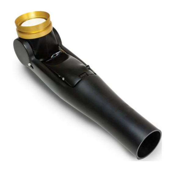
Page 20: The Lamination Collar And Clamp Ring
Orientation of the Lamination Collar The Lamination Collar and Clamp Ring Lamination Collar Humeral Friction Attachment Clamp Internal Rotation The humeral rotation stop pins provide a range of 270° for internal and external rotation. The normal range of human motion is 30° externally and 135°... -
Page 21: Positioning The Input Board In The Lamination Collar
Drive Unit with the Lamination Collar Positioning the input board in the and Clamp Ring installed Lamination Collar Install the Input Connector Board into the Lamination Collar. There are Regardless of whether an elbow will be a left or right, the wires are always three Connectors with gold pins on the Input Board. -
Page 22: Final Adjustment With The User
Attaching To The Elbow Final Adjustment with the User Attach the Clamp Ring and Lamination Collar to the top of the elbow, The humeral rotation is adjusted with a 2.5mm hex key that is supplied with the anti-rotation pin seated in the groove of the elbow, where the with the Clamp Ring. - Page 24 800.728.7950 | 586.294.7950 Learn more at college-park.com/boston-digital-arm...
Need help?
Do you have a question about the LTI BOSTON and is the answer not in the manual?
Questions and answers