Table of Contents
Advertisement
Quick Links
Advertisement
Table of Contents

Related Manuals for College Park CAPITAL


Summary of Contents for College Park CAPITAL
- Page 1 CAPITAL hydraulic knee technical instructions...
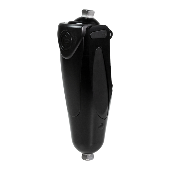
- Page 2 (1) 4 mm Hex Key (1) 2.5 mm Hex Key This diagram is to help familiarize you with the unique parts of the Capital Knee. These parts are referenced in the instructions and used when speaking with a technical service representative.
-
Page 3: Product Description
The Capital Knee is constructed with an integrated pyramid (proximal) and 34 mm pylon receiver or pyramid (distal). INTENDED USE The Capital Knee, intended for transfemoral amputees, is a prosthetic device designed to restore some function of an anatomical knee joint. INDICATIONS: CONTRAINDICATIONS: ▪... - Page 4 ENGLISH BUILD HEIGHT Overall height 9.00 in (230 mm) Dome to knee center 0.67 in (17 mm) Distance from knee center to pyramid center 0.26 in (7 mm) Dome to tube end contact (CHKA J300) 6.80 in (173 mm) Proximal dome to distal dome (CHKA J350) 7.73 in (196 mm)
-
Page 5: Static Alignment
BENCH ALIGNMENT (TKA) ENGLISH Determine the heel height Determine the socket flexion The alignment reference line bisects through the knee center Knee Center Reference STATIC ALIGNMENT With the alignment reference line through the knee center, plantarflex or dorsiflex the foot until the load line is balanced between 1/3 heel and 2/3 toe lever. - Page 6 3-MODE FUNCTION The Capital Knee has three functional modes that can be adjusted by the end user. To change the mode, press down on the mode switch lock, then rotate the switch to the left, center, or right position. When lined up, the lock will click in place.
-
Page 7: Factory Settings
ACCESSING HYDRAULIC ADJUSTMENTS ENGLISH Note: Hydraulic valve adjustments can be made using a 4mm Allen wrench. Note: The full range of valve adjustment is 180° The effect of a dynamic adjustment can be felt with as little as 1/8 - 1/4 turn. FACTORY SETTINGS Remove the hydraulic adjustment cover... - Page 8 SWING PHASE ENGLISH Factory setting = both screws at minimum resistance Begin by adjusting the flexion resistance, or heel rise. Then adjust the extension resistance to control terminal impact. FLEXION RESISTANCE EXTENSION RESISTANCE Controls how quickly the knee goes into flexion upon off- Controls how the knee moves through extension during loading of the prosthesis.
- Page 9 STANCE PHASE ENGLISH Trigger Sensitivity Screw STANCE FLEXION RESISTANCE STANCE TRIGGER SENSITIVITY Factory setting = screw is at maximum resistance Factory setting = screw is at most sensitive (most resistance to stance yielding) (easiest to trigger stance flexion ) This sets the amount of toe load required to trigger Controls flexion of the knee during stance phase of release into flexion.
-
Page 10: Dynamic Adjustments
DYNAMIC ADJUSTMENTS ENGLISH For dynamic adjustments, have your patient begin ambulating at a comfortable cadence to fine-tune the flexion and extension resistance. After the initial settings are established, it is important for the patient to demonstrate walking at variable speeds and on uneven surfaces (ramps, stairs, etc.) in order to fully adjust the knee. - Page 11 STANCE PHASE ENGLISH Stance Flexion Resistance Stance flexion resistance can be evaluated during “stand-to-sit” or descending stairs or ramps. Increase or decrease stance flexion so that the patient can feel appropriate resistance to flexion of the knee during these activities. SYMPTOM DESIRED RESULT SCREW ADJUSTMENT...
-
Page 12: Environmental Conditions
Operating Temperature: -1 - 38° C (30 - 100° F) USE IN WATER The Capital Knee has been approved for use in fresh water. ▪ The knee should be switched into lock mode when using it in or near water. - Page 13 WARRANTY INSPECTION AND MAINTENANCE INFORMATION College Park recommends that you schedule your patients for check-ups per the warranty inspection schedule below. High patient weight or activity level may require more frequent inspections. We recommend you visually inspect the following applicable parts for excessive wear and fatigue at each warranty inspection.
- Page 14 If any problems occur with the use of this product, immediately contact your medical professional. The prosthetist and/or patient should report any serious incident* that has occurred in relation to the device to College Park Industries, Inc. and the competent authority of the Member State in which the prosthetist and/or patient is established.
- Page 16 800.728.7950 | 586.294.7950 | college-park.com 926 INS CHK 200811 Capital: COMPONENTES DE ÓRTESES E PRÓTESES EXTERNAS COLLEGE PARK INDUSTRIES, INC 27955 College Park Dr. Warren, MI 48088 USA ANVISA Registro : 80117580371 IMPORTADOR: EMERGO BRAZIL IMPORT IMPORTAÇÃO DE PRODUTOS MÉDICOS EMERGO EUROPE HOSPITALARES LTDA.
Need help?
Do you have a question about the CAPITAL and is the answer not in the manual?
Questions and answers
Настроить немного изгиб??? Как???
To adjust the bend (flexion and extension resistance) on the College Park CAPITAL knee:
1. Use a 4mm Allen wrench.
2. Remove the hydraulic adjustment cover.
3. Adjust the flexion resistance screw to control heel rise.
4. Adjust the extension resistance screw to control terminal impact.
5. Each valve has a 180° adjustment range.
6. Small changes (1/8 to 1/4 turn) can affect performance.
7. Replace the cover after adjustments.
Use caution in free swing mode to prevent sudden collapse.
This answer is automatically generated