Table of Contents
Advertisement
Advertisement
Table of Contents

Related Manuals for Renishaw Equator 300


Summary of Contents for Renishaw Equator 300
- Page 1 Product information Equator™ 300 gauging system www.renishaw.com/gauging...
-
Page 2: Table Of Contents
Contents Introduction ..........................3 Regulatory information .........................4 Safety information ........................6 Equator 300 gauging system specifications ................10 Working volume .........................13 Equator gauging system overview .....................15 Initial set up ..........................17 Unpacking ..........................18 Connecting cables........................19 Fitting the probe and stylus ......................21 Hardware signals ........................24 Cleaning and maintenance ......................26... -
Page 3: Introduction
Introduction This guide contains general information about the Equator 300 gauging system For information not covered in this guide, please see: • Equator Software Suite user guide • Equator gauging system - MODUS programming guide... -
Page 4: Regulatory Information
Renishaw plc declares that the Equator 300, the Equator 300 Extended Height and the Equator controller comply with the applicable standards and regulations. Renishaw plc hereby declares that the Equator 300, the Equator 300 Extended Height and the Equator controller is in compliance with the essential requirements and other relevant provisions of Directive 1999/5/EC. - Page 5 Information to user (FCC Section 15.21) The user is cautioned that any changes or modifications not expressly approved by Renishaw plc or authorised representative could void the user’s authority to operate the equipment.
-
Page 6: Safety Information
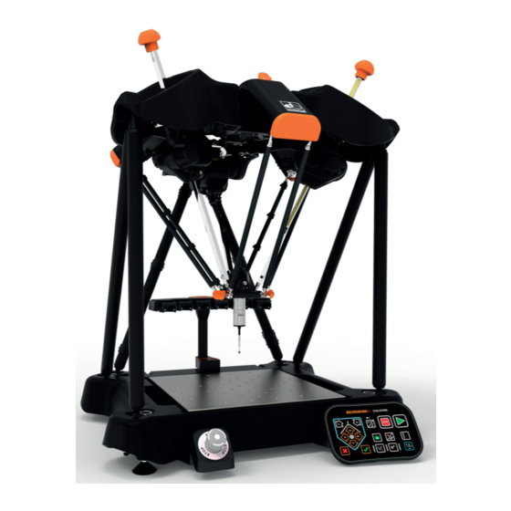
Safety information The image below describes the different parts of the Equator, which are referenced in the following safety information sections. 1. Base casting with hand-hold locations 13. Fixture plate 2. Probe assembly 14. Piece part and fixture 3. Floating or movement platform 15. - Page 7 • Lifting or moving the Equator should only be attempted by two people, using the-hand hold locations provided in the base casting (1). • Do not move or lift the machine by the top casting (5), the support arms of the constraint mechanism (9), the support legs (4), or the three drive struts (e.g.
- Page 8 3.1 Electrical safety • There are no user serviceable parts inside this equipment. • The Equator must be connected to a supply incorporating a protective earth conductor via a three core mains cable. • The equipment is isolated from AC power by disconnection of the IEC mains connector. If any additional means of isolation is required, it must be specified and fitted by the machine manufacturer or the installer of the product.
- Page 9 3.2 Personal protective equipment information To reduce the risk of injury, the wearing of safety goggles and safety shoes is recommended when working within the vicinity of this machine.* Never lean on any part of the machine, and keep a minimum of one metre clearance zone around the volume of the machine when it is operating.
-
Page 10: Equator 300 Gauging System Specifications
** Customers should complete their own risk assessment on delivery of the machine to define their own PPE requirements. Equator machine specifications - Scanning Probe type Renishaw 3 axis SP25 analogue scanning probe Operating temperature +10 °C to +40 °C Maximum scanning velocity... - Page 11 Equator machine specifications - Touch Trigger Probe type Renishaw 3 axis TP20 kinematic touch-trigger probe Operating temperature +10 °C to +40 °C Maximum touch point velocity 10 mm/s Maximum touch acceleration 1500 mm/s Maximum move velocity 500 mm/s Maximum move acceleration...
- Page 12 Equator controller labels Label A (front) Label B (back) Label C (back) 1. USB connectors 3. USB connectors 10. Equator PCI express connector 2. Standby button 4. Monitor connectors 11. Equator 24 V power supply connector 5. Audio connectors 6. Ethernet connector 7.
-
Page 13: Working Volume
Working volume Equator 300 working volume Equator 300 Extended Height working volume... - Page 14 NOTE: When working with very short styli, it is sometimes necessary to add a fixture plate spacer. More information is available at www.renishaw.com/equator-accessories. In manual or joystick mode, if a movement outside the working volume is attempted, the machine will stop moving.
-
Page 15: Equator Gauging System Overview
The programmable Equator system includes all of the above as well as the following components: • Joystick • MODUS Equator software • USB dongle (enables MODUS Equator software) NOTE: Further styli may be required, dependent on the user's requirements. More information is available at http://www.renishaw.com/styli. - Page 16 1. Base casting with hand hold locations 2. Probe assembly 3. Floating or movement platform 4. Support strut or leg 5. Top casting 6. Drive strut 7. Counter balance mechanism 8. Hooke's joints 9. Support arm for parallel kinematic constraint mechanism 10.
-
Page 17: Initial Set Up
Initial set up The following section describes how to set up the Equator gauging system hardware: Unpacking ..........................18 Connecting cables........................19 Fitting the probe and stylus ......................21 Hardware signals ........................24... -
Page 18: Unpacking
Unpacking When the Equator has been removed from its transit packaging according to the instructions attached to the box, please follow the instructions in the following sections to start the system. Contents of boxes The Equator gauging system is delivered in several boxes. The larger box contains the machine and relevant accessories, other boxes contain the controller, stop button or joystick, probe kit and relevant accessories. -
Page 19: Connecting Cables
Connecting cables Connect cables according to the diagram below in the specifi ed order (steps 8 and 9). - Page 20 A-5504-0065 A-5504-0065 A-5504-0070 A-5504-0070 W.1: For further safety information, refer to the Equator Controller quick-start guide. W.2: Be careful to connect the PCIexpress cable in the correct orientation, as failing to do so can cause serious damage to the electronics. Refer to step 8.1. W.3: Ensure all cables are connected prior to connecting to mains.
-
Page 21: Fitting The Probe And Stylus
Fitting the probe and stylus Compatibility A-5504-0065 A-5504-0070 Not Touch Trigger compatible Touch Trigger compatible Fitting the probe body The probe body may already be fitted. See the images below. If the probe body is fitted, proceed to the next step. If it is not fitted, it can be found in either the SP25 or TP20 probe kit box, numbered 0 as shown below, together with printed instructions for installation. - Page 22 Scanning - SP25 probe kit (A-5504-0205) Touch Trigger - TP20 probe kit (A-5926-0201) 0. Probe body - SP25 0. Probe body - EP25 1. 17 × 6 stylus for calibration artefact 1. 17 × 6 stylus for calibration artefact 2. Probe auto joint tool 2.
- Page 23 Fitting the probe module and stylus 1. Push the Stop button to disable all machine motion. Make a habit of doing this whenever human interaction is about to take place and manual mode is not activated. 2. Attach the probe module (SM25-2 or TM25-20) to the probe body, with the SM25-2 or TM25-20 text to the front.
-
Page 24: Hardware Signals
Hardware signals A-5504-0065 machines NOTE: The following information is only applicable to A-5504-0065 machines, identifiable by LED lights on the base casting. To aid trouble shooting, there are three LEDs located at the back right of the base casting. To view the LEDs, remove the fixture plate as shown below. - Page 25 The rear LED can either be pulsing green or off. When green, it indicates that the Equator machine is connected and communicating to the controller. The other two LEDs indicate the status of the drive struts; they are green if the servos are engaged, orange if the system is powered and ready to engage, and red if there is an error preventing servos from engaging.
-
Page 26: Cleaning And Maintenance
The Equator controller has no internal serviceable parts. In the event of a problem, please contact your supplier for assistance. An Equator controller Fan Filter Kit (A-5696-0120) containing 12 fan filters can be purchased from Renishaw ensuring 6 months worth of filters for high contamination environments. - Page 27 Stylus balls should be regularly inspected for damage or ‘pick-up’ of component material (a problem sometimes encountered with continuous scanning). Renishaw offers a range of ball materials suited to scanning of different component materials. See Renishaw’s styli catalogue (part number H-1000- 3200), which can be downloaded from www.renishaw.com/styli.
-
Page 28: Decommissioning
4. Disconnect screen, mouse and keyboard from the controller. 5. Unplug the stop button. 6. If returning the system to Renishaw as part of the RBE scheme, repackage the system using the reverse of the unpacking instructions. If not, dispose of system according to WEEE regulations... - Page 29 © 2019 Renishaw plc. All rights reserved. Renishaw reserves the right to change specifications without notice. RENISHAW and the probe symbol used in the RENISHAW logo are registered trade marks of Renishaw plc in the United Kingdom and other countries. Part no.: H-5504-8705-07-B apply innovation and names and designations of other Renishaw products and technologies are trade marks of Renishaw plc or its subsidiaries.
Need help?
Do you have a question about the Equator 300 and is the answer not in the manual?
Questions and answers