
Subscribe to Our Youtube Channel
Related Manuals for Renishaw Equator


Summary of Contents for Renishaw Equator
- Page 1 Installation guide H-5504-8640-01-A Equator™ gauging system www.renishaw.com/gauging...
- Page 2 REGARDING THE CONTENT. RENISHAW EXCLUDES LIABILITY, HOWSOEVER ARISING, FOR ANY INACCURACIES IN THIS DOCUMENT. Patents Features of Renishaw’s Equator and similar products are the subject of the following patents and patent applications: CNw 100402873C China 0516/CNw/0 JPw 3,294,269 Japan 0211/JPw/0...
- Page 3 Renishaw distributor. EU declaration of conformity Renishaw plc hereby declares that the Equator 300/500, the Equator 300/500 Extended Height and the Equator Controller is in compliance with the essential requirements and other relevant provisions of the applicable EU directives.
-
Page 4: Table Of Contents
Specifications ..............................5 Equator 300 gauging system specifications ..................... 8 Equator 300 gauging system geometry ......................10 Equator 300 Extended Height gauging system geometry ................12 Equator 500 gauging system specifications ....................14 Equator 500 gauging system geometry ......................16 Equator 500 Extended Height gauging system geometry ................ -
Page 5: Specifications
Specifications This guide contains information on the following Equator™ gauging system models. Equator™ 300 Equator™ 300 Extended Height A-5504-0040 A-5504-0050 Equator™ 500 Equator™ 500 Extended Height A-6078-0070 A-6078-0085... - Page 6 The Equator gauging system comprises the Equator gauging machine, the Equator Controller and the probing system. The Equator gauging system can be an Operator only system or a Programmable system. The Operator Equator system includes the following components: • Equator gauging machine •...
- Page 7 *When using a 75 mm × Ø8 mm stylus. When shorter styli are used, the ‘clearance' below the working volume is intended to allow for the use of component holding fixtures, i.e. fixturing can be used without consuming any of the Equator's working volume.
-
Page 8: Equator 300 Gauging System Specifications
Equator 300 gauging system specifications 1. Base casting with hand hold locations 9. Support arm for parallel constraint mechanism 2. SP25 probe assembly 10. CE marking and serial number 3. Floating or moving platform 11. Drive housing 4. Support strut 12. - Page 9 Guards None The process of measuring on an Equator involves defining a series of gauge points on the component surface. Periodic calibration of a master part on a CMM establishes datum values for each gauge point. The same gauge points on the same master part are measured on Equator (known as ‘mastering’) to establish a correlation with the certified CMM.
-
Page 10: Equator 300 Gauging System Geometry
Equator 300 gauging system geometry... - Page 11 Collision geometry...
-
Page 12: Equator 300 Extended Height Gauging System Geometry
Equator 300 Extended Height gauging system geometry... - Page 13 Collision geometry...
-
Page 14: Equator 500 Gauging System Specifications
Equator 500 gauging system specifications 1. Base casting 10. CE marking and serial number 2. SP25 probe assembly 11. Drive housing 3. Floating or moving platform 12. Parallel constraint mechanism 4. Support strut 13. Fixture plate 5. Top casting 14. Workpiece and fixture 6. - Page 15 Guards None The process of measuring on an Equator involves defining a series of gauge points on the component surface. Periodic calibration of a master part on a CMM establishes datum values for each gauge point. The same gauge points on the same master part are measured on Equator (known as ‘mastering’) to establish a correlation with the certified CMM.
-
Page 16: Equator 500 Gauging System Geometry
Equator 500 gauging system geometry... - Page 17 Collision geometry...
-
Page 18: Equator 500 Extended Height Gauging System Geometry
Equator 500 Extended Height gauging system geometry... - Page 19 Collision geometry...
-
Page 20: Equator Controller Specifications - Version 08
Equator Controller specifications - Version 08 11. 4x USB 2.0 ports 1. Power button 12. Display Port 1 and 2 (DPP1 & DPP2) 2. 2x USB 3.0 ports 13. Digital Visual Interface (DVI) 3. Fans and filters 14. 2x USB 3.0 ports 4. - Page 21 ** 3-axis gauging system taking touch points under DCC control + peak consumption at power-up *** Allow an additional 100 mm for cable connectors and cables Operating conditions The Equator Controller is specified to operate under the following conditions as defined in BS EN 61010- 1:2001. Altitude...
-
Page 22: Equator Controller Specifications - Version 09
Equator Controller specifications - Version 09 11. Display Port 1 and 2 (DPP1 & DPP2) 1. Power button 12. 4x USB 3.1 ports 2. 2x USB 3.0 ports 13. Audio (Audio OUT supported, Mic IN not 3. Fans and filters supported) 4. - Page 23 ** 3-axis gauging system taking touch points under DCC control + peak consumption at power-up *** Allow an additional 100 mm for cable connectors and cables Operating conditions The Equator Controller is specified to operate under the following conditions as defined in BS EN 61010- 1:2001. Altitude...
-
Page 24: Probe Kit Specifications - Scanning
8. M5 to M8 20 mm Spacer 9. M5 to 1/4" 20 mm Spacer 10. Port Adaptor PA25-SH 11. M5 to M5 150 mm Spacer 12. Equator Joint Key 13. Rack Port Clip 14. SH25 Reference Tool 15. SHSP stylus... -
Page 25: Probe Kit Specifications - Touch Trigger
9. M5 to M8 20 mm Spacer 10. M5 to 1/4" 20 mm Spacer 11. M2 D4R L20 and M2 D6R L10 styli 12. EJ2 13. S1 Spanner x 2 14. Wrench Hex Key 2.5 mm 15. Equator Joint Key 16. Rack Port Clip... -
Page 26: Mculite-2 Joystick Specifications
MCUlite-2 joystick specifications 1. Stop button 2. Speed override 3. Slow speed movement buttons 4. Fast speed movement buttons 5. 3-axis joystick 6. Joystick X,Y,Z axis lock buttons 7. Take point / cancel last point button... -
Page 27: Equator Button Interface Specifications
Equator Button Interface specifications 1. Z- direction button 2. Z+ direction button 3. Off/Reset button 4. Stop button 5. Play button 6. Y+ direction button 7. X- and X+ direction buttons 8. Y- direction button 9. Recovery button 10. Switch windows button 11. -
Page 28: Safety
Safety Equator 300 safety information ........................29 Equator 500 safety information ........................32 Equator Controller ............................35 Personal protective equipment information ....................36... -
Page 29: Equator 300 Safety Information
Equator 300 safety information 1. Base casting with hand hold locations 9. Support arm for parallel constraint mechanism 2. SP25 probe assembly 10. CE marking and serial number 3. Floating or moving platform 11. Drive housing 4. Support strut 12. Parallel constraint mechanism 5. - Page 30 • When connecting a joystick, stop button or Button Interface (15) to the Equator, it must be disconnected from the mains power supply. Not doing so can cause damage to the circuitry.
- Page 31 • CE mark and serial number (10) are located underneath the front support arm for the constraint mechanism (9).
-
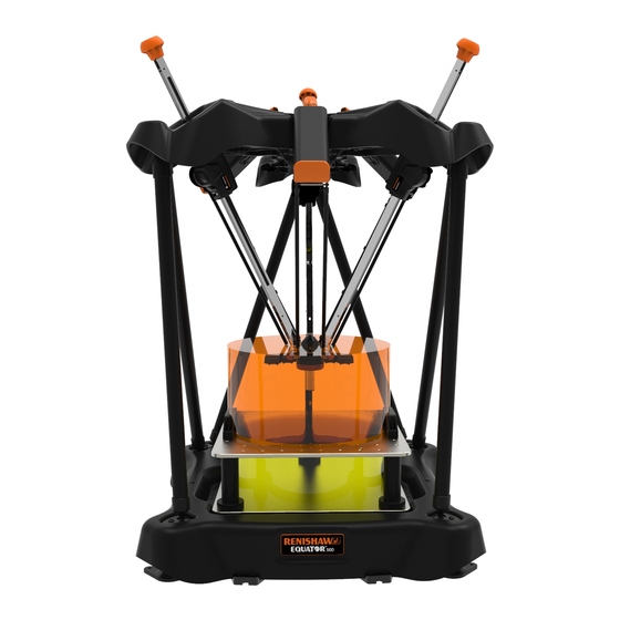
Page 32: Equator 500 Safety Information
Equator 500 safety information The image below describes the different parts of the Equator 500 gauging system, which are referenced in the following safety information sections. 1. Base casting 10. CE marking and serial number 2. SP25 probe assembly 11. Drive housing 3. - Page 33 The Equator 500 should only be mechanically lifted using, for example, a gantry crane, forklift, etc. There are eye bolts (16) on the top casting of the Equator 500 to allow for the use of lifting straps or a harness.
- Page 34 To avoid unexpected movements of the Equator, always recalibrate all probing tools after importing a new environment into Equator Server. • When connecting an Equator Autojoint Adapter (17) to the Equator, it must be disconnected from the mains power supply. Not doing so can cause damage to the circuitry. •...
-
Page 35: Equator Controller
The isolator must be sited within easy reach of the operator and comply with BS EN IEC 61010-1:2001 and any applicable national wiring regulations for the country of installation. • The Equator Controller can be placed either standing or lying on its side, but should be given a reasonable protection from liquid spillage. •... -
Page 36: Personal Protective Equipment Information
Personal protective equipment information To reduce the risk of injury, the wearing of safety goggles and safety shoes is recommended when working within the vicinity of this machine.* Never lean on any part of the machine, and keep a minimum of 0.5 m clearance zone around the volume of the machine when it is operating. -
Page 37: Shipping/Handling/Storage
The unpacked Equator 500 system (without a fixture plate) weighs 75 kgs. It is therefore not recommended that it be manually lifted. The Equator 500 system has eye bolts on the top which can be used to lift the machine using a hoist or gantry crane. It is recommended that a suitable forked mechanical lifting system, mechanical hoist or gantry crane be available for the manoeuvring and positioning of the machine. - Page 38 The Equator 500 should only be mechanically lifted using, for example, a gantry crane, forklift, etc. There are eye bolts on the top casting of the Equator 500 to allow for the use of lifting straps or a harness. Each eye bolt supplied with the Equator 500 has been rated to a safe working load of 240 kg, and manufactured to DIN 850.
-
Page 39: Unboxing The Equator 300
Unboxing the Equator 300 H-5504-8540-02-A www.renishaw.com/gauging Equator quick start guide www.renishaw.com/contacts © 2013 Renishaw plc. All rights reserved. Issued 10.2013... -
Page 41: Unboxing The Equator 500
Unboxing the Equator 500... -
Page 43: Installation
Equator machine positioning • The Equator system needs to be placed on a flat and sturdy surface. It is advised that a 1 m diameter clearance of other objects is established to avoid collisions. •... -
Page 44: Connecting Cables - Equator 300
2.1. Monitor power cable 2.2. Controller power cable W.1: For further safety information, refer to the Equator Controller quick-start guide. W.2: Be careful to connect the PCIexpress cable in the correct orientation, as failing to do so can cause serious damage to the electronics. Refer to step 8.1. - Page 45 W.4: Power outputs must not exceed these limits • (P1) 24 V ± 3% 4 A (MAX CONTINUOUS) 5 A (MAX PEAK) • (P2) 48 V ± 3% 4 A (MAX CONTINUOUS) 8 A (MAX PEAK) • (P1 & P2) COMBINED (48 V & 24 V) CONTINUOUS POWER OUTPUT MUST BE LESS THAN 300 W NOTE: Both Ethernet ports (LAN 1, LAN 2) cannot be connected to the same network.
-
Page 46: Connecting Cables - Equator 500
2.1. Monitor power cable 2.2. Controller power cable W.1: For further safety information, refer to the Equator Controller quick-start guide. W.2: Be careful to connect the PCIexpress cable in the correct orientation, as failing to do so can cause serious damage to the electronics. Refer to step 8.1. - Page 47 W.4: Power outputs must not exceed these limits • (P1) 24 V ± 3% 4 A (MAX CONTINUOUS) 5 A (MAX PEAK) • (P2) 48 V ± 3% 4 A (MAX CONTINUOUS) 8 A (MAX PEAK) • (P1 & P2) COMBINED (48 V & 24 V) CONTINUOUS POWER OUTPUT MUST BE LESS THAN 300 W NOTE: Both Ethernet ports (LAN 1, LAN 2) cannot be connected to the same network.
-
Page 48: Connecting Probe System - Equator 300
Connecting probe system - Equator 300... -
Page 50: Connecting Probe Adaptor - Equator 500
Connecting probe adaptor - Equator 500... -
Page 51: Connecting Probe System - Equator 500
Connecting probe system - Equator 500... -
Page 53: Connecting Styli
Connecting styli Attach the stylus to the probe module. The silver alignment marking should be towards you. There is a faint click when the magnets lock the kinematic coupling in place. Equator 300 Equator 500... -
Page 54: Downloading Equator License And Software Suite
1. Note the serial number of your Equator machine, your Equator Controller and, for a programmer's system, your MODUS dongle. The serial numbers can be found underneath the front support arm, on the back of the controller and on the side of the dongle, as shown below. - Page 55 To ensure you have the latest version of the Equator Software Suite and language packs, please visit: www.renishaw.com/gaugingsupport/software-downloads regularly and follow the on-screen instructions. • Download the Equator Software Suite and language pack files and save them onto a USB flash drive.
-
Page 56: Operation
Operation Stop button, joystick and Equator Button Interface ..................57 Moving the platform manually (Equator 300 only) ..................59 Workpiece and fixture plate loading ....................... 60 Starting the system............................61 Activating a system license ..........................62 Homing ................................63 Calibrating the tools ............................65 Locating the EQR-6 autochange rack - Part 1 .................... -
Page 57: Stop Button, Joystick And Equator Button Interface
Stop button, joystick and Equator Button Interface Depending on its specification, an Equator can be equipped with either a stop button, joystick or Equator Button Interface. The joystick contains an integrated stop button and therefore a separate stop button is not required. - Page 58 Stop button Depending on the specification of the Equator, the stop button is either located on the left hand side of the base or is an integral component of the joystick. The stop button is intended to be used to reduce the risk of collisions by allowing the user to stop the motion of the machine.
-
Page 59: Moving The Platform Manually (Equator 300 Only)
Moving the platform manually (Equator 300 only) NOTE: Only move the platform manually if an error has caused Equator to stop with the stylus in a region where the joystick and manual mode button do not work. • Before entering the working volume, activate the stop button. This ensures that the machine will not start to move automatically. -
Page 60: Workpiece And Fixture Plate Loading
Fixture plate location The repeatable positioning of the fixture plate on the Equator’s base casting is controlled by the kinematic locations found on the base casting and on the underside of the fixture plate. Use of the kinematic location minimises the requirement to carry out an initial location of a component within... -
Page 61: Starting The System
Starting the system • Switch on electrical power to the display (VDU) and the controller unit. The software will start to load automatically and the start-up screen will be displayed. Please wait until all the software has loaded before you continue. •... -
Page 62: Activating A System License
Activating a system license • Once you have downloaded the system license file from the Renishaw website, plug the USB flash drive containing the license file into one of the controller USB ports. • Click on the key icon at the bottom right hand corner of the screen. -
Page 63: Homing
Homing • Click on “Organiser”. • Please wait until the homing message appears (Homing is about to commence. Please ensure nothing obstructs the homing path. If homing is cancelled then limited functionality will be available). • Click on the “green tick” to continue. Homing is the procedure by which the machine locates the probe's position in the working volume by moving to the zero positions of each individual scale (referencing). - Page 64 1. The homing sequence starts with movements in all directions to trigger each light gate twice. 2. Once a roughly central position is found, the Equator will move towards the end position of each scale until it registers the reference mark, starting with the strut at the back of the machine (axis labelled P).
-
Page 65: Calibrating The Tools
Calibrating the tools The first time you run the system, you need to assemble the calibration artefact and fit it to the fixture plate before calibrating the RefTool and locating the EQR-6 autochange rack. The probing tools must be calibrated so that the system knows the location and size of each of the styli. Failure to calibrate the probe will result in an error between the actual contact point (touch point) of the probe’s stylus and the position reported by the system. - Page 66 • Start by loosely screwing the 17 × 6 stylus (1) into the calibration stand (3). • Screw on the relevant thread adapter (4) for the fixture plate (M6, M8 or ¼-20 UNC) tightly (T). • Ensure the calibration artefact is firmly attached to the fixture plate. Also ensure that all spheres are clean and undamaged.
- Page 67 • In Organiser, open the “Toolbox” folder. • Open the “RefTool Calibration” part program. • Click on the “Calibrate probes” button.
- Page 68 • The following message is displayed (Position tool so that stylus points directly at Sphere Centre_PlusZ_ Sphere). • Position the tip over the calibration sphere and click “OK” • The system will automatically measure the calibration sphere; this measurement will pre-set the deflections of the probe.
-
Page 69: Locating The Eqr-6 Autochange Rack - Part 1
Locating the EQR-6 autochange rack - Part 1 NOTE: Ensure the rack is empty of all styli. Locating the rack is done in two steps. • Open the “Rack Location” part program located within the “Toolbox” folder. • The following window is displayed. •... - Page 70 • The following message is displayed (Overwrite master data?). • Click on the “green tick”. • The following message is displayed (Select module in use). • Click on the relevant “SELECT” button. • The following message is displayed (Please attach the SHSP tool (part no. A-2237-0682) then click OK). •...
- Page 71 NOTE:The probe will now move to a safe position. • The following message is displayed (Ensure all 6 port lid clips are applied). • Insert the port lid clips as instructed and click “OK” to continue. NOTE: The probe will now begin to move and start to calibrate the rack. •...
-
Page 72: Locating The Eqr-6 Autochange Rack - Part 2
Locating the EQR-6 autochange rack - Part 2 • In Manager, click “Diagnostics”. • Click “Locate Rack Part 2”. • The program will open. Click on the “Start” button, located in the top left of the screen. • The rack is now fully located. •... -
Page 73: System Shutdown
The following message is displayed (Are you sure that you want to shutdown the Controller?). • Click “Yes” and the system will shutdown. NOTE: If park is enabled and the docking mechanism is present, the Equator 300 system will park prior to shutting down. - Page 74 • If a collision with the part occurs when parking, the following message is displayed (Obstruction encountered. Please clear any obstructions before retrying). • Clear any obstructions and either “Retry Park” or “Continue without Park”. • If the stop button is engage when parking, the following message is displayed (Stop button is engaged. Please disengage Stop button before retrying).
-
Page 75: Cleaning And Maintenance
The Equator controller has fan filters needing regular replacement to ensure satisfactory cooling of internal parts. The Equator controller has no internal serviceable parts. In the event of a problem, please contact your supplier for assistance. An Equator controller Fan Filter Kit (A-5696-0120) containing 12 fan filters can be purchased from Renishaw ensuring 6 months worth of filters for high contamination environments. - Page 76 Regular checks should be made to make sure that the electrical connectors are properly located. Controller fan filter maintenance The fan intakes on the front of the Equator Controller have filters to prevent dust and other particles from entering. These filters should be replaced regularly to prevent overheating of the controller.
-
Page 77: Diagnosing Faults
Diagnosing Faults Equator 300 lights and signals ........................78 Equator 500 lights and signals ........................79 Error messages and common errors ......................80... -
Page 78: Equator 300 Lights And Signals
Equator 300 lights and signals Left Machine Meaning Right Probe State Meaning State Grey - Off No power Grey - Off No power Solid red Machine disengaged - fault Solid red Probe fault / over range state Red flashing No communications... -
Page 79: Equator 500 Lights And Signals
Equator 500 lights and signals Floating platform Drives H-6078-2760-01-A.pdf 1 1/6/2017 12:12:20 PM Colour Drive Platform left Platform right No power No power No power No power Machine disengaged/ Machine disengaged/ Machine disengaged/ Solid red Probe fault error error error... -
Page 80: Error Messages And Common Errors
Error messages and common errors Error messages Messages from all Equator software will be displayed in Organiser. The first warning messages will be displayed with an error type and description, ending with a standard message "Contact your supervisor". A second message informs you that the inspection failed and continued attempts were aborted. -
Page 81: Dismantling And Disposal
6. Unplug the stop button. 7. If returning the system to Renishaw as part of the RBE scheme, repackage the system using the reverse of the unpacking instructions. If not, dispose of the system according to the WEEE regulations (see the WEEE... - Page 82 Renishaw reserves the right to change specifications without notice. Original instructions RENISHAW and the probe symbol used in the RENISHAW logo are registered trade marks of Renishaw plc in the United Kingdom and other countries. Part no.: H-5504-8640-01-A apply innovation and names and designations of other Renishaw products and technologies are trade marks of Renishaw plc or its subsidiaries.
Need help?
Do you have a question about the Equator and is the answer not in the manual?
Questions and answers