Table of Contents
Advertisement
Installation Instructions
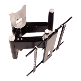
QA2 & QA2-60 - Quad Arm
Design Highlights
-Parallel Track for beautifully tight recessed finish
-Bidirectional rotating head for 150 degree rotation
-Smooth quiet motion
-Full Cable Management
-Range of preset positions
-Onboard Electronics
Thank you for choosing
futureautomation
email info@futureautomation.co.uk tel: +44 (0) 1438 833577 fax: +44 (0) 1438 833565
ISSUE 001
Advertisement
Table of Contents

Related Manuals for Future Automation QA2-60


Summary of Contents for Future Automation QA2-60
-
Page 1: Installation Instructions
Installation Instructions QA2 & QA2-60 - Quad Arm Design Highlights -Parallel Track for beautifully tight recessed finish -Bidirectional rotating head for 150 degree rotation -Smooth quiet motion -Full Cable Management -Range of preset positions -Onboard Electronics Thank you for choosing futureautomation email info@futureautomation.co.uk tel: +44 (0) 1438 833577 fax: +44 (0) 1438 833565... -
Page 2: Safety Information
Exceeding the weight capacity can result in serious personal injury or damage to equipment. Future Sound & Vision trading as Future Automation intend to make this and all documentation as accurate as possible. However, Future Automation makes no claim that the information contained herein covers all details, conditions or variations, nor does it provide for every possible contingency in connection with the installation or use of this product. -
Page 3: Table Of Contents
QA2 & QA2-60 - Quad Arm Contents Page Introduction Safety Information Contents Contents Tool Indicator Icons Product Warranty Installation Parts List Package Contents Stage 1 Before you Start Check the Following Stage 2 Screen Upright Mounting Stage 3 Fitting the Mechanism to the Wall... -
Page 4: Contents
Any damage to products during transit that is not checked and notified as “unchecked” or “damaged” upon receipt of delivery. Any part of your system that needs to be replaced during a warranty repair becomes the property of Future Automation. -
Page 5: Package Contents
QA2 & QA2-60 - Quad Arm Nuts & Bolts Multipack: Package Contents A range of nuts, bolts, washers and spacers to help add in the 1 - Mechanism mounting for your screen 1.1 - Screen Mount Plate 1.2 - Wall Mount Plate (Your pack may also contain a 1.3 - Screen Upright... -
Page 6: Before You Start Check The Following
QA2 & QA2-60 - Quad Arm Before you Start, Check the Following: -The product is in good condition -No damage to any parts -Wiring is all secure -The unit is in the closed position -Remove transit red cable ties before operating... -
Page 7: Screen Upright Mounting
QA2 & QA2-60 - Quad Arm Screen Upright Mounting First release the screen uprights by removing the bolt on the upright restraints shown in the detail view below. Align the uprights on the rear of the screen and measure down to the wall plate fixing holes so mounting height can be determined on the wall. -
Page 8: Fitting The Mechanism To The Wall
QA2 & QA2-60 - Quad Arm Fitting the Mechanism to the Wall Once you have decided on the location of your screen you can fix the wall plate to the wall. -Fix through one of the top holes first. -Using the wall plate as a template, mark the other holes before drilling into the wall. -
Page 9: Removing Panel Covers
QA2 & QA2-60 - Quad Arm Removing Panel Covers Power the mechanism half way out so all the arm cover panels are accessible. Remove the bolts and 4 cover panels so the interiors of the arms are accessible. Page 8 of 22 // email info@futureautomation.co.uk tel: +44 (0) 1438 833577 fax: +44 (0) 1438 833565... -
Page 10: Cable Management
QA2 & QA2-60 - Quad Arm Cable Management Feed the screen, speaker and signal cables though the bottom of the mechanism and then out into the lower arm, then up the elbow tube and out into the upper arm. Then out the lower face of the upper arm and through the centre of the screen plate ready to connect to the screen. -
Page 11: Testing Mechanism & Replacing The Panel Covers
QA2 & QA2-60 - Quad Arm Testing Mechanism & Replacing Panel Covers This is a good point to test the mechanism and make sure it’s working properly. Make sure cables are restrained/cable tied in the arms and have enough slack for movement. -
Page 12: Mounting The Screen
QA2 & QA2-60 - Quad Arm Mounting the Screen Hook the screen back over the mount bars and lock in place by fixing the bolts back through the upright restraints. Screen Uprights Upright Restraints Mount Bars Page 11 of 22 // email info@futureautomation.co.uk tel: +44 (0) 1438 833577 fax: +44 (0) 1438 833565... -
Page 13: Marine Lock Option
QA2 & QA2-60 - Quad Arm Marine Lock Option An optional marine lock is available which locks the mechanism in the IN position against the wall, making it suitable for indoor marine installations. Latch Bracket PRODUCT CODES QA2 M QA2 60 M... -
Page 14: Final Checks & Set Up
QA2 & QA2-60 - Quad Arm Final Checks & Set Up -Make sure that all side panels are fitted securely in place -Nothing is obstructing the movement of the mechanism or screen -Product is square and level on the wall... -
Page 15: Manual Head Rotation
QA2 & QA2-60 - Quad Arm Manual Head Rotation To manually adjust the parallel head position remove the top head inner plate as shown in the detail view. Head Angle Head Inner Plate Page 14 of 22 // email info@futureautomation.co.uk tel: +44 (0) 1438 833577 fax: +44 (0) 1438 833565... -
Page 16: Manual Head Rotation
QA2 & QA2-60 - Quad Arm Manual Head Rotation Loosen the 4 rotational locking bolts circled in red in the detail view. X4 Rotational Locking Bolts Manually rotate the head into the desired parallel postion then lock back in place by... -
Page 17: Operation Buttons For The Ir Remote
QA2 & QA2-60 - Quad Arm Operation Buttons for the IR Remote In - Brings the bracket Stop - Will stop fully in, parallel to the wall the operation at any position Out - Moves the arm out, Preset - Moves arm to recess... -
Page 18: Contact Closure
QA2 & QA2-60 - Quad Arm Contact Closure Use an RJ45 connector in the CC1 socket on the control box to operate via contact closure WIRE / CABLE CONTACT CLOSURE DESCRIPTION ACTION 568A 568B LED INDICATOR 12V SUPPLY 12V SUPPLY - CURRENT LIMITED When 12V attached, device will go OUT. -
Page 19: Rs232
QA2 & QA2-60 - Quad Arm RS232 - Use an RJ25 connector in the socket marked RS232 on the control box to operate using RS232 Details RJ25 9 PIN D Baud rate: 9600 PIN 1: RX PIN 2: TX Stop bit:... -
Page 20: Connectivity Details
QA2 & QA2-60 - Quad Arm Connectivity Details QA2 60, QA2 M & QA2 60 M UDC3 BOARD UDC4 BOARD RS232 RS232 Contact Contact Closure Closure Mains Voltage IR LED IR LED Mains Input Voltage Input EMERGENCY STOP EMERGENCY STOP... -
Page 21: Trouble Shooting
QA2 & QA2-60 - Quad Arm Wall Mount QA2 - Trouble shooting For information & technical support on our products please refer to the relevant web site or phone number - General Contact info@futureautomation.co.uk +44 (0)1438 833577 US Contact info@futureautomation.net +1 (603) 742 9181 Page 20 of 22 // email info@futureautomation.co.uk tel: +44 (0) 1438 833577 fax: +44 (0) 1438 833565... -
Page 22: Technical Overview
QA2 & QA2-60 - Quad Arm Technical Overview A general technical overview of the QA2 two way electric wall mount. Page 21 of 22 // email info@futureautomation.co.uk tel: +44 (0) 1438 833577 fax: +44 (0) 1438 833565... - Page 23 QA2 & QA2-60 - Quad Arm Notes... Page 22 of 22 // email info@futureautomation.co.uk tel: +44 (0) 1438 833577 fax: +44 (0) 1438 833565...
- Page 24 Future Automation Unit 2 Kimpton Enterprise Park Claggy Road Kimpton Hertfordshire SG4 8HP United Kingdom Tel: +44 (0) 1438 833 577 Fax: +44 (0) 1438 833 565 Email: info@futureautomation.co.uk www.futureautomation.co.uk...
Need help?
Do you have a question about the QA2-60 and is the answer not in the manual?
Questions and answers