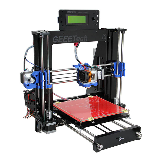
Geeetech Acrylic Prusa I3 Pro B Assemble Instruction
Hide thumbs
Also See for Acrylic Prusa I3 Pro B:
- Building instruction (114 pages) ,
- Assemble instruction (100 pages) ,
- User manual (35 pages)
Advertisement
Quick Links
Advertisement

Related Manuals for Geeetech Acrylic Prusa I3 Pro B


Summary of Contents for Geeetech Acrylic Prusa I3 Pro B
- Page 1 Assemble Instruction of Geeetech Acrylic Prusa I3 Pro & pro B...
-
Page 2: Unfold The Box And Check The Package
1. This kit contains tiny parts; please keep them away from kids under 3. 2. This building instruction applies to both Geeetech Acrylic Prusa I3 pro and pro B. 3. Some pictures of the printed part may be a bit different from those in your package, no worries, they work the same, and the way to assemble is similar. - Page 3 Shenzhen GETECH CO.,LTD GEEETECH All the acrylic plate has been etched with part ID and the plate is covered with a sheet of kraft paper, you need to tear them off. www.geeetech.com Tel: +86 755 2658 4110 Fax: +86 755 2658 4074 ‐ 858 ...
- Page 4 Shenzhen GETECH CO.,LTD GEEETECH www.geeetech.com Tel: +86 755 2658 4110 Fax: +86 755 2658 4074 ‐ 858 ...
- Page 5 1) Thread the acrylic fender (Y plate connecting plate) in the middle. 2) Thread the M10 washer > M8 spring washer >M10 nut > M10 nut > M10 washer on the left www.geeetech.com Tel: +86 755 2658 4110 Fax: +86 755 2658 4074 ‐ 858 ...
- Page 6 Required parts Required number Part ID M8 smooth rod NO.3 LM8UU Linear bearings NO.39 Slide 2 bearings on each smooth rod. Before you slide the bearings please make sure they are clean. www.geeetech.com Tel: +86 755 2658 4110 Fax: +86 755 2658 4074 ‐ 858 ...
- Page 7 Step1. Slide the rods into the acrylic plate; adjust the length so that the smooth rods fit snugly between the front and rear piece. Step2. Screw up the rods and plate with M10 nut and M10 washer. www.geeetech.com Tel: +86 755 2658 4110 Fax: +86 755 2658 4074 ‐ 858 ...
- Page 8 2.2 Assemble the Y idler Required parts Required number Part ID 624ZZ Ball bearing NO.38 bearing holder NO.66 M3 x 20 screw NO.27 M3 wing nut NO.15 M4 x25 screw NO.35 www.geeetech.com Tel: +86 755 2658 4110 Fax: +86 755 2658 4074 ‐ 858 ...
- Page 9 Step1. Thread the M3 x 20 screw through the bearing holder. Step2. Put the M4 x25 screw through the holes with the two 624ZZ bearings in between. Lock the other end with a M4 lock nut. www.geeetech.com Tel: +86 755 2658 4110 Fax: +86 755 2658 4074 ‐ 858 ...
- Page 10 Step3. Mount the assembled bearing holder onto the front support plates. And screw it with a wing nut. *Please leave enough room for the belt between the ball bearing and the screw. www.geeetech.com Tel: +86 755 2658 4110 Fax: +86 755 2658 4074 ‐ 858 ...
- Page 11 NO.16 Step1. Mount the pulley on the motor shaft, one of the screws should be screwed on the cross section of the shaft. Do not screw too tight to turn smoothly. www.geeetech.com Tel: +86 755 2658 4110 Fax: +86 755 2658 4074 ‐ 858 ...
- Page 12 But be careful in case the Acrylic broke down. Then screw the motor on the block plate with 3 M3 x 12 screws and fix the block plate with 2 M3 x 16 screws and M3 square nut. www.geeetech.com Tel: +86 755 2658 4110 Fax: +86 755 2658 4074 ‐ 858 ...
- Page 13 NO.54 M3 x 10 screw NO.24 M3 x 20 screw NO.27 M3 nut NO.11 Step1. Mount the belt mount on the bottom side of the platform with 2 M3 x 10 www.geeetech.com Tel: +86 755 2658 4110 Fax: +86 755 2658 4074 ‐ 858 ...
- Page 14 Shenzhen GETECH CO.,LTD GEEETECH screws. Step2. Mount the 4 bearing blocks on the platform with M3 x 20 screws on the same side with the belt-mount. Screw with M3 nuts. www.geeetech.com Tel: +86 755 2658 4110 Fax: +86 755 2658 4074 ‐ 858 ...
- Page 15 Shenzhen GETECH CO.,LTD GEEETECH Step3. Get the build platform plate zip-tied to the 4 linear bearings of Y- Axis. *The belt-mount and the fenders are under the platform. www.geeetech.com Tel: +86 755 2658 4110 Fax: +86 755 2658 4074 ‐ 858 ...
- Page 16 2. Loosen the Y idler wing nut when tightening belt onto the Y belt mount [No. 67] in order to make securing the belt to the block easier. Be sure to tighten wing nut fully o nce done. www.geeetech.com Tel: +86 755 2658 4110 Fax: +86 755 2658 4074 ‐ 858 ...
- Page 17 Step1. Held upright the main frame is after the acrylic fender washers on the threaded rods. Here you can use the A2 panel as a reference to measure the distance A1 and A12 (the rear plate). www.geeetech.com Tel: +86 755 2658 4110 Fax: +86 755 2658 4074 ‐ 858 ...
- Page 18 Step2. Screw up the main frame to the acrylic fender with M3 x 20 screws. Step3. Screw up the M10 screw on the threaded rod of Y-axis. You can see the www.geeetech.com Tel: +86 755 2658 4110 Fax: +86 755 2658 4074 ‐ 858 ...
-
Page 19: Mount The Fan
Fix the fan on the right side of the frame with 4 M3 x 30 screw and locknut. Mind the direction of the wires. (Please pay attention to the fan not others) www.geeetech.com Tel: +86 755 2658 4110 Fax: +86 755 2658 4074 ‐ 858 ... -
Page 20: Assemble The Right And Left Side Panel
Acrylic right frame NO.A3 M3 x 16 screw NO.26 M3 square nut NO.16 Step1. Screw up the X-Z frame and the side panel then connect the rear part of the Y www.geeetech.com Tel: +86 755 2658 4110 Fax: +86 755 2658 4074 ‐ 858 ... - Page 21 Z Motor support plate NO.A6, A7 M3 x 16 screw NO.26 M3 square nut NO.16 Step1. It would be easier to mount the A4/A5 to A6 and A7 first, and then mount the www.geeetech.com Tel: +86 755 2658 4110 Fax: +86 755 2658 4074 ‐ 858 ...
- Page 22 M3 x 16 screws and M3 square nuts. *The right and left bottom mount are different; the left one has a mount for the Z end stop. Please look at the following picture. www.geeetech.com Tel: +86 755 2658 4110 Fax: +86 755 2658 4074 ‐ 858 ...
- Page 23 Shenzhen GETECH CO.,LTD GEEETECH 6.2 Assemble the 2 Z motors Required parts Required number Part ID Stepper Motor NO.75 M3 x 12screw NO.25 www.geeetech.com Tel: +86 755 2658 4110 Fax: +86 755 2658 4074 ‐ 858 ...
- Page 24 Shenzhen GETECH CO.,LTD GEEETECH Step1.Thread the wires of the motors through the holes www.geeetech.com Tel: +86 755 2658 4110 Fax: +86 755 2658 4074 ‐ 858 ...
- Page 25 Do the same with the other Z motor. 7 Assemble the X axis (the horizontal axis) 7.1 Assemble the smooth rods. Required parts Required number Part ID 370mm smooth rod NO.2 www.geeetech.com Tel: +86 755 2658 4110 Fax: +86 755 2658 4074 ‐ 858 ...
- Page 26 Required number Part ID 624ZZ Ball bearing NO.38 Bearing holder NO. 66 M3 X30 screw NO.28 M4 X25 screw NO.35 M4 locknut NO.14 Step1. Put the screw through the Y bearing holder. www.geeetech.com Tel: +86 755 2658 4110 Fax: +86 755 2658 4074 ‐ 858 ...
- Page 27 Shenzhen GETECH CO.,LTD GEEETECH Step2. Thread the M4 x 25 screw through the holder with the 624ZZ bearings in between. Lock the other end of a M4 nut. www.geeetech.com Tel: +86 755 2658 4110 Fax: +86 755 2658 4074 ‐ 858 ...
- Page 28 Step1. Mount the assembled idler into the right X-axis end. Here, you can insert the linear bearing into the end. Step2. Lock it up with a wing nut and insert a linear bearing into the slot. www.geeetech.com Tel: +86 755 2658 4110 Fax: +86 755 2658 4074 ‐ 858 ...
- Page 29 Shenzhen GETECH CO.,LTD GEEETECH Step3. Insert another linear bearing into the slot of left end. Then lock the bearing with M3x 16 screw and nut. Do the same to the right end. www.geeetech.com Tel: +86 755 2658 4110 Fax: +86 755 2658 4074 ‐ 858 ...
- Page 30 7.4 Assemble the X-axis rods and both ends Required parts Required number Part ID Brass nut NO.17 M3 x 16 screw NO.26 M3 x50 screw NO.31 M3 nut NO.11 Screw locking ring NO.19 www.geeetech.com Tel: +86 755 2658 4110 Fax: +86 755 2658 4074 ‐ 858 ...
- Page 31 NO.54 NO.40 LM8UU linear bearing Step1. Mount the print bracket on the smooth rods. 1) Insert the linear bearings into the slot of the bracket as you can see from the www.geeetech.com Tel: +86 755 2658 4110 Fax: +86 755 2658 4074 ‐ 858 ...
- Page 32 7.6 Mount the extruder holder. Required parts Required number Part ID Extruder bracket NO.P4 M4 x 16screw NO.34 M4 nut NO.11A Step1. Put the 2 M4 nut into the hole, as shown in the picture. www.geeetech.com Tel: +86 755 2658 4110 Fax: +86 755 2658 4074 ‐ 858 ...
- Page 33 Shenzhen GETECH CO.,LTD GEEETECH Step2. Screw up the belt bracket and the extruder support with two M4 x 16screws. www.geeetech.com Tel: +86 755 2658 4110 Fax: +86 755 2658 4074 ‐ 858 ...
- Page 34 Shenzhen GETECH CO.,LTD GEEETECH 7.7 Mount the extruder Required parts Required number Part ID MK8 extruder NO.79 MK8 assemble board NO.65 M4 x 12 screw NO.33 M4 nut NO.11A www.geeetech.com Tel: +86 755 2658 4110 Fax: +86 755 2658 4074 ‐ 858 ...
- Page 35 Shenzhen GETECH CO.,LTD GEEETECH Look at the picture below, this is the fully assembled MK8 extruder in the package. Step1. You should take the nozzle part and the bolt out. www.geeetech.com Tel: +86 755 2658 4110 Fax: +86 755 2658 4074 ‐ 858 ...
- Page 36 Shenzhen GETECH CO.,LTD GEEETECH Step2. Mount the aluminum plate between the extruder. Step3. Mount the assembled extruder on the extruder support. Use 2 M4 x 12 screws and M4 nut to fix. www.geeetech.com Tel: +86 755 2658 4110 Fax: +86 755 2658 4074 ‐ 858 ...
- Page 37 Required number Part ID Stepper motor NO.75 Pulley NO.43 M3 x 8 screw NO.23 lease pay attention to the mount direction of the pulley, which is opposite to that of the Y-axis. www.geeetech.com Tel: +86 755 2658 4110 Fax: +86 755 2658 4074 ‐ 858 ...
- Page 38 Shenzhen GETECH CO.,LTD GEEETECH www.geeetech.com Tel: +86 755 2658 4110 Fax: +86 755 2658 4074 ‐ 858 ...
- Page 39 Step2. Another end of the belt should be threaded through the belt holder on the right end of the X-axis. (The belt holder in the picture is different from yours, do not worry, it is ok for you to understand) www.geeetech.com Tel: +86 755 2658 4110 Fax: +86 755 2658 4074 ‐ 858 ...
- Page 40 (This bracket may be a bit different from yours, but it doesn’t matter) * do not rush to cut the belt in this step, you may not estimate the length accurate, you can adjust it after you assemble the Z axis. www.geeetech.com Tel: +86 755 2658 4110 Fax: +86 755 2658 4074 ‐ 858 ...
-
Page 41: Assemble The X-Z Axis
Step1. Fix the two couplings on both of the threaded rod. And plug it on the motor shaft. *Mind the opening of the couplings, the larger opening should be connected to the threaded rods. www.geeetech.com Tel: +86 755 2658 4110 Fax: +86 755 2658 4074 ‐ 858 ... - Page 42 Shenzhen GETECH CO.,LTD GEEETECH Step2. Thread the threaded rods of Z axis through the brass nuts. It would be easier to do it now. Keep both end of the X axis flush. www.geeetech.com Tel: +86 755 2658 4110 Fax: +86 755 2658 4074 ‐ 858 ...
- Page 43 Step3. Put the assembled X-axis on the Z-axis. Then slide the smooth rod into the linear bearings. Step4. Assemble the top mount of the Z-axis. Required parts Required number Part ID Z-axis top mount NO.A8 M3 x 16 screw NO.26 M3 square nut NO.16 www.geeetech.com Tel: +86 755 2658 4110 Fax: +86 755 2658 4074 ‐ 858 ...
- Page 44 Shenzhen GETECH CO.,LTD GEEETECH 9. Attach he heated bed. Required parts Required number Part ID MK2A Heat bed NO.71 Borosilicate glass NO.72 Heating wire NO.51 www.geeetech.com Tel: +86 755 2658 4110 Fax: +86 755 2658 4074 ‐ 858 ...
- Page 45 *All our heated bed is pre-soldered before shipping; you can attach the bed directly here. The following steps are just for reference if you need to change the bed in the future. Step1. Solder the heating wire on the edge of the bed. www.geeetech.com Tel: +86 755 2658 4110 Fax: +86 755 2658 4074 ‐ 858 ...
- Page 46 Shenzhen GETECH CO.,LTD GEEETECH Step2. Take out the 2-pin DuPont wire and take off one the adapter. Step3. Solder the DuPont wire and the thermistor together. www.geeetech.com Tel: +86 755 2658 4110 Fax: +86 755 2658 4074 ‐ 858 ...
- Page 47 Step4. Attach the DuPont wire and the thermistor on the bed with Kapton tape. Step5. Mount the heat bed on the platform with 4 M3 x35 screws and wing nuts with www.geeetech.com Tel: +86 755 2658 4110 Fax: +86 755 2658 4074 ‐ 858 ...
- Page 48 *the soldered side is better to be attached downwards. Mount the end stops. Step 1.End stop of X-axis Required parts Required number Part ID End stop NO.44 M2.5 X 12 screw NO.21 www.geeetech.com Tel: +86 755 2658 4110 Fax: +86 755 2658 4074 ‐ 858 ...
- Page 49 Part ID End stop NO.45 M2.5 X 16 screw NO.22 M2.5 Hex nut NO.10 Note: there is no “+” and “-” for endstops, so there is no difference for the wires. www.geeetech.com Tel: +86 755 2658 4110 Fax: +86 755 2658 4074 ‐ 858 ...
- Page 50 Shenzhen GETECH CO.,LTD GEEETECH Step3. End stop of Z-axis Required parts Required number Part ID End stop NO.46 M 3 X 16 screw NO.26 M 3 nut NO.11 www.geeetech.com Tel: +86 755 2658 4110 Fax: +86 755 2658 4074 ‐ 858 ...
- Page 51 11 Mount the LCD panel frame. Required parts Required number Part ID LCD 2004 NO.80 LCD frame NO.A21 LCD frame holder NO.A23 Acrylic washer NO.A20 M3 x 20 screw NO.27 M3 nut NO.11 www.geeetech.com Tel: +86 755 2658 4110 Fax: +86 755 2658 4074 ‐ 858 ...
- Page 52 Shenzhen GETECH CO.,LTD GEEETECH If you can not make the LCD frame stand on the A1, you can put another fender (Part No.46) on the third screws. www.geeetech.com Tel: +86 755 2658 4110 Fax: +86 755 2658 4074 ‐ 858 ...
- Page 53 Step1. Mount the PSU (Power supply unit) on the right side panel with 3 M3 x 10 screws. Step2. Mount the AC socket with M3 x 16 screws. First you have to take off one end of the connectors to get both the power button and www.geeetech.com Tel: +86 755 2658 4110 Fax: +86 755 2658 4074 ‐ 858 ...
- Page 54 Shenzhen GETECH CO.,LTD GEEETECH the power socket into the hole. *(The connection of wire in this picture is very important; you should pay close www.geeetech.com Tel: +86 755 2658 4110 Fax: +86 755 2658 4074 ‐ 858 ...
- Page 55 2) Pay attention to the switch on the right side of the PSU, there are two options of voltage: 110 V and 220V, choose according the standard in your country. As shown in the following picture. You can use some hard sticks to reach the switch. www.geeetech.com Tel: +86 755 2658 4110 Fax: +86 755 2658 4074 ‐ 858 ...
- Page 56 Shenzhen GETECH CO.,LTD GEEETECH see the finished picture here. www.geeetech.com Tel: +86 755 2658 4110 Fax: +86 755 2658 4074 ‐ 858 ...
- Page 57 Step1. Plug the jumper caps on the following pins of the board. (In the yellow circle) The jumper caps are packaged along with the board, do not lost them. These caps are very tiny; do not throw them away inadvertently. www.geeetech.com Tel: +86 755 2658 4110 Fax: +86 755 2658 4074 ‐ 858 ...
- Page 58 As shown in the picture, plug the jumper caps into the red block. Step2. Stack the 4 A4988 on stepper motor driver slot. Mind the orientation of the A4988, as shown in the blue blocks. www.geeetech.com Tel: +86 755 2658 4110 Fax: +86 755 2658 4074 ‐ 858 ...
- Page 59 Step4. Connect the heating wires. There is no “+” and “-“ for heating wire. 1) Connect the heating wires for bed. Loosen the screws and plug the wires into the connectors, then screw up it. www.geeetech.com Tel: +86 755 2658 4110 Fax: +86 755 2658 4074 ‐ 858 ...
- Page 60 Shenzhen GETECH CO.,LTD GEEETECH 2) Connect the heating wires for extruder. www.geeetech.com Tel: +86 755 2658 4110 Fax: +86 755 2658 4074 ‐ 858 ...
- Page 61 Shenzhen GETECH CO.,LTD GEEETECH Step5. Connect the thermistor wires. red is “+” and black is “-“. 1) Connect the thermistor wire for bed. 1) Connect the thermistor wire for extruder. www.geeetech.com Tel: +86 755 2658 4110 Fax: +86 755 2658 4074 ‐ 858 ...
- Page 62 Shenzhen GETECH CO.,LTD GEEETECH Step6. Connect the motor wires. 1) Connect X axis motor. www.geeetech.com Tel: +86 755 2658 4110 Fax: +86 755 2658 4074 ‐ 858 ...
- Page 63 Note: when connect the other Z-motor, use the 4-pin M-F DuPont cable and pay attention to the directions of the wire. If you connect them reversely, the 2 Z motor will move in different directions. Look at the colors of the wire. www.geeetech.com Tel: +86 755 2658 4110 Fax: +86 755 2658 4074 ‐ 858 ...
- Page 64 Shenzhen GETECH CO.,LTD GEEETECH Plug the DuPont wire into the 4-pin close the to the first Z motor. www.geeetech.com Tel: +86 755 2658 4110 Fax: +86 755 2658 4074 ‐ 858 ...
- Page 65 Shenzhen GETECH CO.,LTD GEEETECH 4) Connect the motors for extruder. Step7. Connect end stops. There is no “+” and “-“ for end stops. www.geeetech.com Tel: +86 755 2658 4110 Fax: +86 755 2658 4074 ‐ 858 ...
- Page 66 Shenzhen GETECH CO.,LTD GEEETECH Step8. Connect fan. The three 12V GND is for fan, you can use any two of them. www.geeetech.com Tel: +86 755 2658 4110 Fax: +86 755 2658 4074 ‐ 858 ...
- Page 67 Shenzhen GETECH CO.,LTD GEEETECH Note: you need to use the 2-pin Dupont wire to extend the wire for the fan of extruder. Step9. Connect power cable for the board. www.geeetech.com Tel: +86 755 2658 4110 Fax: +86 755 2658 4074 ‐ 858 ...
- Page 68 Shenzhen GETECH CO.,LTD GEEETECH www.geeetech.com Tel: +86 755 2658 4110 Fax: +86 755 2658 4074 ‐ 858 ...
- Page 69 Shenzhen GETECH CO.,LTD GEEETECH That is all wiring for Sanguinololu. www.geeetech.com Tel: +86 755 2658 4110 Fax: +86 755 2658 4074 ‐ 858 ...
- Page 70 Shenzhen GETECH CO.,LTD GEEETECH Example 2: Ramps 1.4 Step1. Plug the jumper caps on ramps 1.4. You need 15 jumper caps in total. Step2. Stack ramps 1.4 onto mega 2560. www.geeetech.com Tel: +86 755 2658 4110 Fax: +86 755 2658 4074 ‐ 858 ...
- Page 71 Shenzhen GETECH CO.,LTD GEEETECH Step3. Plug the 4 A4988 motor driver boards on ramps1.4; stick the heat sinks on the driver boards. 3 for X, Y axis and extruder, 1 for Z axis www.geeetech.com Tel: +86 755 2658 4110 Fax: +86 755 2658 4074 ‐ 858 ...
- Page 72 Shenzhen GETECH CO.,LTD GEEETECH Step5. Mind the directions of the driver boards. You can see the “GND” on the board. www.geeetech.com Tel: +86 755 2658 4110 Fax: +86 755 2658 4074 ‐ 858 ...
- Page 73 Shenzhen GETECH CO.,LTD GEEETECH Wiring To make you see clearly, I will divide them into several parts separately. The referring wiring schematic diagram of Ramps 1.4 www.geeetech.com Tel: +86 755 2658 4110 Fax: +86 755 2658 4074 ‐ 858 ...
- Page 74 Shenzhen GETECH CO.,LTD GEEETECH Step1. Connect motors. X and Y motors are easier; here you need to notice the Z motor, you need 2 4-pin DuPont cable to extend for Z motor. www.geeetech.com Tel: +86 755 2658 4110 Fax: +86 755 2658 4074 ‐ 858 ...
- Page 75 Step2. Connect the fan; both the fan for extruder and the main board are connected like this. As to the fan for extruder, you need another 2-pin DuPont cable to extend. Take off the adapters and plug the cable into the power port. www.geeetech.com Tel: +86 755 2658 4110 Fax: +86 755 2658 4074 ‐ 858 ...
- Page 76 The thicker red wire is for heating and the 2-pin DuPont wire are for thermometry. Step4. Connect the extruder The 2-pin DuPont cable with adapter is for thermometry, the thicker one is for www.geeetech.com Tel: +86 755 2658 4110 Fax: +86 755 2658 4074 ‐ 858 ...
- Page 77 Shenzhen GETECH CO.,LTD GEEETECH heating. Step5. Connect the end stops. Note that there is no “+” and “-” for the endstoppers. You can connect them as you like. www.geeetech.com Tel: +86 755 2658 4110 Fax: +86 755 2658 4074 ‐ 858 ...
- Page 78 Shenzhen GETECH CO.,LTD GEEETECH Step6. Connect the power supply. First you should take off the white adapter. Then screw the cable into the power port. Notice the “+” and “-“ www.geeetech.com Tel: +86 755 2658 4110 Fax: +86 755 2658 4074 ‐ 858 ...
- Page 79 Shenzhen GETECH CO.,LTD GEEETECH Red is “+”. Black is “-“. Plug the other end into the PSU. www.geeetech.com Tel: +86 755 2658 4110 Fax: +86 755 2658 4074 ‐ 858 ...
- Page 80 Please pay attention to the direction of the board, the end with Capacitor, power jacks and MOSFET should be mounted towards the fan for better heat dissipation. Or the board will be burned. www.geeetech.com Tel: +86 755 2658 4110 Fax: +86 755 2658 4074 ‐ 858 ...
- Page 81 15. Tidy out the wires. Use the wire coil to tie put those wires together. There are holes on the acrylic plates for the wires, you can arrange them as you like. www.geeetech.com Tel: +86 755 2658 4110 Fax: +86 755 2658 4074 ‐ 858 ...
- Page 82 M3 square nut NO.16 PVC tube NO.60,61 The whole printer assembly work is already done. Hope you enjoy the whole process. For how to set up the printer, please visit: http://www.geeetech.com/wiki/index.php/Acrylic_Prusa_Mendel_I3 www.geeetech.com Tel: +86 755 2658 4110 Fax: +86 755 2658 4074 ‐ 858 ...
Need help?
Do you have a question about the Acrylic Prusa I3 Pro B and is the answer not in the manual?
Questions and answers