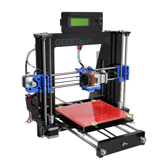
Geeetech Acrylic Prusa I3 Assemble Manual
Hide thumbs
Also See for Acrylic Prusa I3:
- Assembly instructions manual (109 pages) ,
- Assemble manual (59 pages) ,
- Manual (24 pages)
Advertisement
Quick Links
Advertisement

Subscribe to Our Youtube Channel
Related Manuals for Geeetech Acrylic Prusa I3


Summary of Contents for Geeetech Acrylic Prusa I3
- Page 1 Assemble Manual of Geeetech Acrylic Prusa I3 (8mm)
- Page 2 1 Unfold and check the package Unfold the package and take all the parts out to check the condition of the items. As you can see, all the parts are packed very carefully. www.geeetech.com Tel: +86 755 2658 4110 Fax: +86 755 2658 4074 ‐ 858 ...
- Page 3 Shenzhen GETECH CO.,LTD GEEETECH All the acrylic plate has been etched with part ID. www.geeetech.com Tel: +86 755 2658 4110 Fax: +86 755 2658 4074 ‐ 858 ...
- Page 4 2. The part ID is corresponding to the number labeled on the bag of every part. www.geeetech.com Tel: +86 755 2658 4110 Fax: +86 755 2658 4074 ‐ 858 ...
- Page 5 M10 washer > M8 spring washer >M10 screw > M10 screw > M10 washer > acrylic fender > M10 washer > M8 spring washer > M10 screw > M10 screw > M8 spring washer > M10 washer www.geeetech.com Tel: +86 755 2658 4110 Fax: +86 755 2658 4074 ‐ 858 ...
- Page 6 Required parts Required number Part ID M8 smooth rod NO.3 LM8UU Linear bearings NO.39 Slide 2 bearings on each smooth rod. Before you slide the bearings please make sure they are clean. www.geeetech.com Tel: +86 755 2658 4110 Fax: +86 755 2658 4074 ‐ 858 ...
- Page 7 Each corner gets a washer and a nut. Adjust the inner and outer nuts so that the end of the rod is flush with the outside M10 nut. Do the same on all four corners. www.geeetech.com Tel: +86 755 2658 4110 Fax: +86 755 2658 4074 ‐ 858 ...
- Page 8 Tips: the Y-axis must be a rectangle, that is the rods on both side should be parallel, so is the front and back plate. Otherwise it will cause obstruction for the belt later. www.geeetech.com Tel: +86 755 2658 4110 Fax: +86 755 2658 4074 ‐ 858 ...
- Page 9 Step1. Thread the M3 x 20 screw through the Y idler piece. Put the M4 x25 screw through the holes with the 624ZZ bearings in between. Lock the other end with a M3 nut. www.geeetech.com Tel: +86 755 2658 4110 Fax: +86 755 2658 4074 ‐ 858 ...
- Page 10 Step2. Mount the assembled idler onto the front support plates. And screw it with a wing nut. *Please leave enough room for the belt between the ball bearing and the screw. www.geeetech.com Tel: +86 755 2658 4110 Fax: +86 755 2658 4074 ‐ 858 ...
- Page 11 NO.16 Step1. Mount the pulley on the motor shaft, one of the screws should be screwed on the cross section of the shaft. Do not screw too tight to turn smoothly. www.geeetech.com Tel: +86 755 2658 4110 Fax: +86 755 2658 4074 ‐ 858 ...
- Page 12 Insert the motor block into the slot; you may need to use a little strength to do this. But be careful in case the Acrylic broke down. Then screw the motor on the block plate with M3 x 10 screws. www.geeetech.com Tel: +86 755 2658 4110 Fax: +86 755 2658 4074 ‐ 858 ...
- Page 13 M3 x 10 screw NO.24 M3 x 20 screw NO.27 M3 nut NO.11 Step1. Mount the belt mount on the bottom side of the platform with 2 M3 x 10 screws. www.geeetech.com Tel: +86 755 2658 4110 Fax: +86 755 2658 4074 ‐ 858 ...
- Page 14 Step3. Get the build platform plate zip-tied to the 4 linear bearings of Y- Axis. *The belt-mount and the fenders are under the platform. www.geeetech.com Tel: +86 755 2658 4110 Fax: +86 755 2658 4074 ‐ 858 ...
- Page 15 Shenzhen GETECH CO.,LTD GEEETECH Step4. Mount the belt. www.geeetech.com Tel: +86 755 2658 4110 Fax: +86 755 2658 4074 ‐ 858 ...
- Page 16 Thread the belt through the pulley on the Y motor and the Y idler. Drill a hole on the other end of the belt and fix it on the belt -mount with a M3 x 10 screw and washer. Step5. Attach he heated bed. www.geeetech.com Tel: +86 755 2658 4110 Fax: +86 755 2658 4074 ‐ 858 ...
- Page 17 NO.71 Borosilicate glass NO.72 Heating wire NO.51 Thermistor Attached on the bed Thermometry wire NO.50 Wing nut NO.15 Spring NO.37 M3 x35 screw NO.29 clamp NO.52 *The circled part needs soldering. www.geeetech.com Tel: +86 755 2658 4110 Fax: +86 755 2658 4074 ‐ 858 ...
- Page 18 Shenzhen GETECH CO.,LTD GEEETECH Mount the heat bed on the platform with 4 M3 x30 screws and wing nuts with springs in between. Clamp the heat bed and the glass sheet. www.geeetech.com Tel: +86 755 2658 4110 Fax: +86 755 2658 4074 ‐ 858 ...
- Page 19 The front of the plate should be sticking out a lot further than the back. Screw up the frame to the threaded rod of Y-axis. Required parts Required number Part ID X-Z frame NO.A1 Acrylic fender NO.A12 M3 x 20 screw NO.27 M3 nut NO.11 www.geeetech.com Tel: +86 755 2658 4110 Fax: +86 755 2658 4074 ‐ 858 ...
-
Page 20: Mount The Fan
M3 x 30 screw NO.28 M3 locknut NO.13 Fix the fan on the right side of the frame with 4 M3 x 30 screw and locknut. Mind the direction of the wires. www.geeetech.com Tel: +86 755 2658 4110 Fax: +86 755 2658 4074 ‐ 858 ... -
Page 21: Assemble The Right And Left Side Panel
Shenzhen GETECH CO.,LTD GEEETECH 5 Assemble the right and left side panel Required parts Required number Part ID Acrylic left panel NO.A2 Acrylic right panel NO.A3 M3 x 16 screw NO.26 www.geeetech.com Tel: +86 755 2658 4110 Fax: +86 755 2658 4074 ‐ 858 ... - Page 22 6.1 Assemble the Z-axis bottom mount Required parts Required number Part ID Z Motor fixed plate NO.A4, A5 Z Motor support plate NO.A6, A7 M3 x 16 screw NO.26 M3 square nut NO.16 www.geeetech.com Tel: +86 755 2658 4110 Fax: +86 755 2658 4074 ‐ 858 ...
- Page 23 M3 x 20 screws and M3 square nuts. *The right and left bottom mount are different; the left one has a mount for the Z end stop. Please look at the following picture. www.geeetech.com Tel: +86 755 2658 4110 Fax: +86 755 2658 4074 ‐ 858 ...
- Page 24 Shenzhen GETECH CO.,LTD GEEETECH 6.2 Assemble the 2 Z motors Required parts Required number Part ID Stepper Motor NO.76 M3 x 12screw NO.25 Step1.Thread the wires of the motors through the holes www.geeetech.com Tel: +86 755 2658 4110 Fax: +86 755 2658 4074 ‐ 858 ...
- Page 25 Shenzhen GETECH CO.,LTD GEEETECH Step2. Screw up the motors with M3 x 12 screws. www.geeetech.com Tel: +86 755 2658 4110 Fax: +86 755 2658 4074 ‐ 858 ...
- Page 26 Shenzhen GETECH CO.,LTD GEEETECH www.geeetech.com Tel: +86 755 2658 4110 Fax: +86 755 2658 4074 ‐ 858 ...
- Page 27 NO.15 NO.P2 X-axis end NO.40 LM8UU linear bearing Put the screw through the printed Y idler piece, with the 624ZZ bearings in between. Lock the other end of a M3 nut. www.geeetech.com Tel: +86 755 2658 4110 Fax: +86 755 2658 4074 ‐ 858 ...
- Page 28 Shenzhen GETECH CO.,LTD GEEETECH Mount the assembled idler into the X-axis end. Lock it up with a wing nut. Here, you can insert the linear bearing into the end. www.geeetech.com Tel: +86 755 2658 4110 Fax: +86 755 2658 4074 ‐ 858 ...
- Page 29 Shenzhen GETECH CO.,LTD GEEETECH Insert a linear bearing into the other end of X-axis. www.geeetech.com Tel: +86 755 2658 4110 Fax: +86 755 2658 4074 ‐ 858 ...
- Page 30 Slide the two bearings into the two rods respectively. Then thread the two locking fender into the right end of both rods. Thread the two rods into the two X-axis ends and then mount the brass nut under both ends. www.geeetech.com Tel: +86 755 2658 4110 Fax: +86 755 2658 4074 ‐ 858 ...
- Page 31 Step1. Mount the X-axis belt bracket on the smooth rods. As you can see from the picture, the two linear bearings should be placed into the two slot of the bracket. Tie them up with zip ties. www.geeetech.com Tel: +86 755 2658 4110 Fax: +86 755 2658 4074 ‐ 858 ...
- Page 32 Shenzhen GETECH CO.,LTD GEEETECH 8.2 Mount the extruder support. Required parts Required number Part ID Extruder bracket NO.P4 M4 x 16 screw NO.34 M4 lock nut NO.14 www.geeetech.com Tel: +86 755 2658 4110 Fax: +86 755 2658 4074 ‐ 858 ...
- Page 33 Shenzhen GETECH CO.,LTD GEEETECH www.geeetech.com Tel: +86 755 2658 4110 Fax: +86 755 2658 4074 ‐ 858 ...
- Page 34 Shenzhen GETECH CO.,LTD GEEETECH 8.3 Mount the extruder Required parts Required number Part ID MK8 extruder NO.80 MK8 assemble board NO.65 M4 x 8 screw NO.32 M4 x 12 screw NO.33 www.geeetech.com Tel: +86 755 2658 4110 Fax: +86 755 2658 4074 ‐ 858 ...
- Page 35 Shenzhen GETECH CO.,LTD GEEETECH This is the fully assembled MK8 extruder in the package. Take the nozzle part and the bolt out. www.geeetech.com Tel: +86 755 2658 4110 Fax: +86 755 2658 4074 ‐ 858 ...
- Page 36 Mount the aluminum plate under the extruder. Use 2 M4 x 8 screws to fix. Then mount the assembled extruder on the extruder bracket. Use 2 M4 x 16 screws to www.geeetech.com Tel: +86 755 2658 4110 Fax: +86 755 2658 4074 ‐ 858 ...
- Page 37 Shenzhen GETECH CO.,LTD GEEETECH fix. 8.4 Mount the X-axis motor. Required parts Required number Part ID Stepper motor NO.76 Pulley NO.43 M3 x 8 screw NO.23 www.geeetech.com Tel: +86 755 2658 4110 Fax: +86 755 2658 4074 ‐ 858 ...
- Page 38 Shenzhen GETECH CO.,LTD GEEETECH www.geeetech.com Tel: +86 755 2658 4110 Fax: +86 755 2658 4074 ‐ 858 ...
- Page 39 Thread the belt through the motor end. The belt is attached on the pulley. Another end of the belt should be threaded through the belt holder on the right end of the X-axis. www.geeetech.com Tel: +86 755 2658 4110 Fax: +86 755 2658 4074 ‐ 858 ...
- Page 40 Shenzhen GETECH CO.,LTD GEEETECH *Pay attention to the tooth mesh of the belt and that on the bracket. Tie up both ends tightly. www.geeetech.com Tel: +86 755 2658 4110 Fax: +86 755 2658 4074 ‐ 858 ...
-
Page 41: Assemble The X-Z Axis
9 Assemble the X-Z axis. Step1. Thread the threaded rod of Z axis through the following part. It would be easier to do it now. Required parts Required number Part ID L300 threaded rod NO.4 www.geeetech.com Tel: +86 755 2658 4110 Fax: +86 755 2658 4074 ‐ 858 ... - Page 42 Step2. Fix the two couplings on both of the threaded rod. And plug it on the motor shaft. Required parts Required number Part ID couplings NO.67 *Mind the opening of the couplings, the larger opening should be put into the shaft of the motor. www.geeetech.com Tel: +86 755 2658 4110 Fax: +86 755 2658 4074 ‐ 858 ...
- Page 43 Step3. Put the assembled X-axis on the Z-axis. Then slide the smooth rod into the linear bearings. Step4. Assemble the top mount of the Z-axis. Required parts Required number Part ID Z-axis top mount NO.A8 M3 x 16 screw NO.26 M3 square nut NO.16 www.geeetech.com Tel: +86 755 2658 4110 Fax: +86 755 2658 4074 ‐ 858 ...
- Page 44 Shenzhen GETECH CO.,LTD GEEETECH Mount the end stops. Step 1.End stop of X-axis Required parts Required number Part ID End stop NO.44 M2.5 X 12 screw NO.21 www.geeetech.com Tel: +86 755 2658 4110 Fax: +86 755 2658 4074 ‐ 858 ...
- Page 45 Shenzhen GETECH CO.,LTD GEEETECH Step2. End stop of Y-axis Required parts Required number Part ID End stop NO.45 M2.5 X 16 screw NO.22 M2.5 Hex nut NO.10 www.geeetech.com Tel: +86 755 2658 4110 Fax: +86 755 2658 4074 ‐ 858 ...
- Page 46 Shenzhen GETECH CO.,LTD GEEETECH Step3. End stop of Z-axis Required parts Required number Part ID End stop NO.46 M2.5 X 16 screw NO.22 www.geeetech.com Tel: +86 755 2658 4110 Fax: +86 755 2658 4074 ‐ 858 ...
- Page 47 11 Mount the LCD panel frame. Required parts Required number Part ID LCD 2004 NO.79 LCD frame NO.A22 LCD frame holder NO.A24 Acrylic washer NO.A21 M3 x 20 screw NO.27 M3 nut NO.11 www.geeetech.com Tel: +86 755 2658 4110 Fax: +86 755 2658 4074 ‐ 858 ...
- Page 48 Shenzhen GETECH CO.,LTD GEEETECH www.geeetech.com Tel: +86 755 2658 4110 Fax: +86 755 2658 4074 ‐ 858 ...
- Page 49 M3 square nut NO.16 PVC tube NO.60,61 13 Mount the PSU Required parts Required number Part ID NO.74 M4 x 12 screw NO.33 M3 x 20 screw NO.27 M3 nut NO.11 www.geeetech.com Tel: +86 755 2658 4110 Fax: +86 755 2658 4074 ‐ 858 ...
- Page 50 Then mount the AC socket with M3 x 20 screws. You have to take off one end of the connectors to get both the power button and the power socket into the hole. www.geeetech.com Tel: +86 755 2658 4110 Fax: +86 755 2658 4074 ‐ 858 ...
- Page 51 Shenzhen GETECH CO.,LTD GEEETECH 1. Mind the color of the wires. The wrong connection of the wire will cause serious damage to the PSU and even to the control board of the printer. www.geeetech.com Tel: +86 755 2658 4110 Fax: +86 755 2658 4074 ‐ 858 ...
- Page 52 These caps are very tiny; do not throw them away inadvertently. The jumper caps are packaged along with the board, do not lost them. You need to plug 12 caps in all. www.geeetech.com Tel: +86 755 2658 4110 Fax: +86 755 2658 4074 ‐ 858 ...
- Page 53 Shenzhen GETECH CO.,LTD GEEETECH Step2. Stack the 5 A4988 on Sanguinololu www.geeetech.com Tel: +86 755 2658 4110 Fax: +86 755 2658 4074 ‐ 858 ...
- Page 54 Shenzhen GETECH CO.,LTD GEEETECH Step3. Stick the heat sink on the chip of the 4 A4988. www.geeetech.com Tel: +86 755 2658 4110 Fax: +86 755 2658 4074 ‐ 858 ...
- Page 55 Note: when connect the other Y-motor, use the 4-pin M-F DuPont cable and pay attention to the directions of the wire. If you connect them reversely, the 2 Z motor will move in different directions. Look at the colors of the wire. www.geeetech.com Tel: +86 755 2658 4110 Fax: +86 755 2658 4074 ‐ 858 ...
- Page 56 The referring wiring schematic diagram of Ramps 1.4 For more information about ramps 1.4, please visit the ramps 1.4 wiki Step5. Mount the board on the left side panel of the printer. And cover the board with www.geeetech.com Tel: +86 755 2658 4110 Fax: +86 755 2658 4074 ‐ 858 ...
- Page 57 M3x20 screw NO.27 M3 x 40 screw NO.30 M3 nut NO.11 All the wires can be tied together under the printer, but you should make sure they don’t touch the belt. www.geeetech.com Tel: +86 755 2658 4110 Fax: +86 755 2658 4074 ‐ 858 ...
- Page 58 Shenzhen GETECH CO.,LTD GEEETECH Arrange the wires and tidy up them with the coil. The whole printer assembly work is already done. Hope you enjoy the whole process. www.geeetech.com Tel: +86 755 2658 4110 Fax: +86 755 2658 4074 ‐ 858 ...
Need help?
Do you have a question about the Acrylic Prusa I3 and is the answer not in the manual?
Questions and answers