Table of Contents
Advertisement
Quick Links
Advertisement
Table of Contents

Subscribe to Our Youtube Channel
Related Manuals for Geeetech Prusa I3 A pro


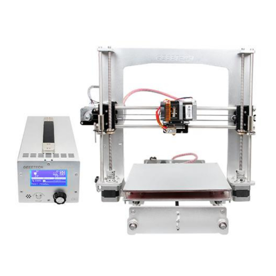
Summary of Contents for Geeetech Prusa I3 A pro
- Page 1 Assembly Instructions of Geeetech Prusa I3 A pro (Version 04-11-2016)
-
Page 2: Table Of Contents
CONTENT Safety Instructions ..........................3 Preparation ............................4 1. Unfold the box and check the package..................1 2. Assemble Y axis ..........................1 3. Build the printing platform ......................11 4. Assemble Y smooth rods ......................12 5. Mount the Y-axis belt ........................13 6. -
Page 3: Safety Instructions
Safety Instructions Building the printer will require a certain amount of physical dexterity, common sense and a thorough understanding of what you are doing. We have provided this detailed instruction to help you assemble it easily. However ultimately we cannot be responsible for your health and safety whilst building or operating the printer, with that in mind be sure you are confident with what you are doing prior to commencing with building or buying. -
Page 4: Preparation
Preparation 1. Unpack the kit and check if all parts are in the box and check the condition of each part, there might be some damage during shipping. To help you with this, there is BOM in the box and each bag was labeled with part number. 2. -
Page 5: Unfold The Box And Check The Package
Shenzhen GETECH CO.,LTD GEEETECH 1. Unfold the box and check the package Unfold the package and take all the parts out to check the condition of the items. As you can see, all the parts are packed very carefully. Tips: 1. - Page 6 Shenzhen GETECH CO.,LTD GEEETECH...
- Page 7 Shenzhen GETECH CO.,LTD GEEETECH 2.2Attach the front and rear side support plates of the rods. VIDEO Required Required parts Part ID number Front Side Support NO. A2 Rear Side Support NO.A3 M10 washer NO.9 M10 nut NO.13 Slide assembled threaded rods into the support plates. Screw up the rods and plates with 4 M10 nuts and M10 washers.
- Page 8 Shenzhen GETECH CO.,LTD GEEETECH bearing holder NO.37 Driving wheel NO.38 M4 lock nut NO.14 Guide Block NO.A8 Guide Block NO.A9 M3 x 25screw NO.24 M4x25 screw NO.28 M3 wing nut NO.15 M3 washer NO.7 M4 washer NO.8 Step1. Amount guide block A and B onto the front support plate together, screw up it...
- Page 9 Shenzhen GETECH CO.,LTD GEEETECH...
- Page 10 Shenzhen GETECH CO.,LTD GEEETECH Note: the guide block B is close to front support plate. Step2. Thread a M3 x25screw and M3washer through the bearing holder.
- Page 11 Shenzhen GETECH CO.,LTD GEEETECH Step3. Insert the two MR84zz ball bearings into both ends of the driving wheel. You will need use some force to do this.
- Page 12 Shenzhen GETECH CO.,LTD GEEETECH Step4. Put the M4 x25 screw and M4 washer through the driving wheel. Lock the other end with a M4 lock nut. You may need a wrench to tighten locking nut. If the holder is too tight, you need to open it a bit.
- Page 13 Shenzhen GETECH CO.,LTD GEEETECH *Do not screw it too tight, you should leave enough room for the wheel to turn freely. Step5. Mount the assembled bearing holder through the guide blocks onto the front support plates. And screw it with a wing nut. (You can also mount it later when assembling the belt) *Please leave enough room for the belt between the ball bearing and the screw.
- Page 14 Shenzhen GETECH CO.,LTD GEEETECH Stepper motor NO.54 pulley NO.41 M3 x 10screw NO.21 M3 washer NO.7 The pulley is changed but it will not affect the assembly and use. So some picture is updated. Step1. Mount the pulley on the motor shaft, one of the screws should be screwed on the cross section of the shaft.
-
Page 15: Build The Printing Platform
Shenzhen GETECH CO.,LTD GEEETECH (In the video, I use the M3x16mm screw at this step; you can use either of them) 3. Build the printing platform VIDEO Required Required parts Part ID number Y building NO.A6 platform Y belt mount... -
Page 16: Assemble Y Smooth Rods
Shenzhen GETECH CO.,LTD GEEETECH PCS8UU linear NO.33 bearing M3 x 10 screw NO.21 M4x12 screw NO.27 M3washer NO.7 M4 washer NO.8 M4 hex nut NO.12 Step1. Mount the belt mount at the middle of the platform with 2 M3 x 10 screws and M3washers. -
Page 17: Mount The Y-Axis Belt
Shenzhen GETECH CO.,LTD GEEETECH *When threading the rod, please make sure the holes are aligned and do not force it, or you will break the balls in the bearings. 5. Mount the Y-axis belt VIDEO Required parts Required number Part ID Timing belt NO.42... - Page 18 Shenzhen GETECH CO.,LTD GEEETECH VIDEO Required parts Required number Part ID X-Z frame NO.A1 Z Motor fixed plate NO. A4 Stepper Motor NO.54 Coupling NO.40 M3 x 16screw NO.22 M3x10 screw NO.21 M3 washer NO.7 Step1. Mount the motor on Z Motor fixed plate, screw it with 4 M3x10screws and M3 washers.
- Page 19 Shenzhen GETECH CO.,LTD GEEETECH Step3. Mount the coupling on the motor shaft, one of the screws should be screwed on the flat side of the shaft (As the picture shows). Screw it as tightly as possible.
-
Page 20: Assemble Y - Z Axis
Shenzhen GETECH CO.,LTD GEEETECH Step4. Repeat the above steps for another Z axis motor. 7. Assemble Y - Z axis VIDEO Required parts Required number Part ID M3 x 16 screw NO.22 M3 washer NO.7 Step1. Held upright the X-Z frame on the threaded rods (Right after the Y connecting plate) Step2. -
Page 21: Attach The Heated Bed
Shenzhen GETECH CO.,LTD GEEETECH 8. Attach the heated bed. VIDEO Required parts Required number Part ID Heat bed NO.49 Spring NO.32 M3 washer NO.7 Hex Counter- NO.29 sunk-head screw Mount the heat bed on the platform with 4 M3 x30Hex Counter-Sunk-head screw and... -
Page 22: Mount The Extension Board
Shenzhen GETECH CO.,LTD GEEETECH *Note: The heating wire is pre-soldered on the bed and the thermometry wire is attached on the bed. The soldered side is better to be attached downwards. 9. Mount the extension board VIDEO Required parts Required number... -
Page 23: Assemble The Left End Of The X Axis(Motor End)
Shenzhen GETECH CO.,LTD GEEETECH Step1. Insert the spacer into the hole on the extension board from back to front. Step2. Fix the spacer on the left back side of X-Z frame with 3 M3x10screws. 10. Assemble the left end of the X axis(motor end) VIDEO 10. - Page 24 Shenzhen GETECH CO.,LTD GEEETECH X-axis motor end No.M1 Linear Bearing No. 35 LMH8LUU M3 x 45 screw No.25 M3 x 6mm screw No. 19 M3 washer No. 7 Spring No. 32 Step1. Mount the Z nut on the X-axis left end from bottom to up, fix with M3 x 6mm screws.
- Page 25 Shenzhen GETECH CO.,LTD GEEETECH If there is no enough room for both the Z nut and the linear bearing, you can move the Z nut upwards, as shown in the following picture:...
- Page 26 Shenzhen GETECH CO.,LTD GEEETECH 10. 3 mount the X motor. Part name Part ID Required number M3 x 6 mm screw No. 19 Stepper motor No.54 Pulley No.41 Step1. Mount the pulley on the motor shaft. Screw it on the flat side.
- Page 27 Shenzhen GETECH CO.,LTD GEEETECH Step 2.Mount the stepper motor on the motor end with 3 M3 x 6 mm screw.
- Page 28 Shenzhen GETECH CO.,LTD GEEETECH 10.4 Mount the endstop Part name Part ID Required number M2.5 x 8 mm No. 17 screw End stop No.46 Mount the endstop on the top of X-axis motor end with 2 M2.5 x 8mm screws...
- Page 29 Shenzhen GETECH CO.,LTD GEEETECH...
-
Page 30: Assemble The Right End Of The X Axis. (X Idler End)
Shenzhen GETECH CO.,LTD GEEETECH 11. Assemble the right end of the X axis. (X idler end) VIDEO Part name Part ID Required number Z-axis nut No.15 X-axis idle end No.M2 Linear Bearing No. 35 LMH8LUU M3 x 6mm screw No.18 Step1.Mount the Z axis nut on the bottom of X-axis right end with 4 M3 x6mm... - Page 31 Shenzhen GETECH CO.,LTD GEEETECH...
-
Page 32: Assembly Of The Extruder Carriage
Shenzhen GETECH CO.,LTD GEEETECH 12. Assembly of the extruder carriage VIDEO Part name Part ID Required number Carriage No.M3 Bearing Bracket No.M4 Extruder holder No.M5 Linear Bearing LM8LUU No.34 Belt bracket No.43 M3x6mm screw No. 18 M3x10mm screw No. 20 M4x6mm screw No. - Page 33 Shenzhen GETECH CO.,LTD GEEETECH Please notice the front and back of the plate. Step2.fix the belt mounts on the back of the carriage with 2 M3x 10mm screws and M3 hex nuts. Step3. Fix the extruder holder on the front side of the X carriage using M4x6mm...
-
Page 34: Assemble The X&Z Axis
Shenzhen GETECH CO.,LTD GEEETECH 13. Assemble the X&Z axis VIDEO Part name Part ID Required number L300mm lead No.4 screw L320mm smooth No.1 L390 mm smooth No.2 locking ring No.31... - Page 35 Shenzhen GETECH CO.,LTD GEEETECH Step1. Thread the lead screw to the nut of both end of X axis. Keep both end of X axis at the same place of the rod, you are advised to measure the distance of the both side so that they are at the same level when you put them up.
-
Page 36: Assemble The Z Axis Top Mount
Shenzhen GETECH CO.,LTD GEEETECH horizontal, which is very important, or it will hinder the move of the Z axis. (This main frame is a bit different from yours but it won’t affect your assembly) 14. Assemble the Z axis top mount... -
Page 37: Belt Driving Wheel
Shenzhen GETECH CO.,LTD GEEETECH Lock screw No.30 Step1. Add the Z top mount (No.A6) to the top of A1. Slowly rotate the rods into the holes. Step2. Screw it up with M3 x 16mm screw. Step3. Use the lock screw to fix thesmooth rodson both top and bottom. - Page 38 Shenzhen GETECH CO.,LTD GEEETECH M3 x45mm screw No.25 M4 x 25mm screw No.29 M4 lock nut No.13 wing nut No.14 Step1. Thread the M3 x 45 screw into the top of the Driven wheel holder. Step2. Insert the two MR84zz ball bearingsinto both ends of the driving wheel.
- Page 39 Shenzhen GETECH CO.,LTD GEEETECH...
- Page 40 Shenzhen GETECH CO.,LTD GEEETECH Step3. Put the M4 x25 screw and M4 washerthrough the driving wheel. Lock the other end with a M4 lock nut. You may need a wrench to tighten locking nut. *Do not screw it too tight, you should leave enough room for the wheel to turn freely.
-
Page 41: Add The Belt
Shenzhen GETECH CO.,LTD GEEETECH 16. Add the belt VIDEO Part name Part ID Required number Timing belt No.42 Belt bracket No.43 Step1. Insert one end of the belt in the groove. Pay attention to the tooth mesh of the belt and the groove. - Page 42 Shenzhen GETECH CO.,LTD GEEETECH...
-
Page 43: Mount The Extruder
Shenzhen GETECH CO.,LTD GEEETECH 17. Mount the extruder VIDEO Part name Part ID Required number Extruder No.59 M4x6mm screw No. 27 M4 washer No.8 Mount the hot end on the extruder holder plate from bottom to up with 2 M4x6mm... -
Page 44: Mount The Endstop Of Y And Z Axis
Shenzhen GETECH CO.,LTD GEEETECH 18. Mount the endstop of Y and Z axis VIDEO Step1. End stop of Y-axis Required parts Required number Part ID End stop NO.46 M2.5 x 12 screw NO.17 M2.5 washer NO.6 Mount Y-axis end stop on the rear side support. Screw it up with M2.5x12 screws and M2.5 washers. - Page 45 Shenzhen GETECH CO.,LTD GEEETECH Step2. End stop of Z-axis Required parts Required number Part ID End stop NO.46 M 2.5x 12 screw NO.17 M2.5 washer NO.6 Mount Z-axis end stop on the left Z motor block. Screw up it with M2.5x12 screws...
-
Page 46: Wiring
Shenzhen GETECH CO.,LTD GEEETECH 19. Wiring... - Page 47 Shenzhen GETECH CO.,LTD GEEETECH Step1. Connect wires for motors. 1) Connect wires for X-axis motor. 2) Connect wires for Y-axis motor.
- Page 48 Shenzhen GETECH CO.,LTD GEEETECH 3) Connect wires for the Z-axis motors. Another z motor...
- Page 49 Shenzhen GETECH CO.,LTD GEEETECH 4) Connect Extruder motor Step2. Connect heating wires. Loosed the screws in the blue terminal and put the red wires into the slot and screw it * There is no “+” and “-“polarityfor heating wires 1) Connect heating wires for heatbed to HB.
- Page 50 Shenzhen GETECH CO.,LTD GEEETECH Step3. Connect wires for thermistor. 1) Connect wires for thermistor of heatbed to TB. (black and red wires) 2) Connect wires for thermistor of extruder to TE0...
- Page 51 Shenzhen GETECH CO.,LTD GEEETECH Step4. Connect wires for endstop. * There is no “+” and “-“polarityforendstop 1) Connect wires for endstop of X-axis to X-min. 2) Connect wires for endstop of Y-axis to Y-min.
- Page 52 Shenzhen GETECH CO.,LTD GEEETECH 3) Connect wires for endstop of Z-axis to Z-min. Step5. Connect wires for Fan of extruder. Here you will need the extension wire for the fan (No.46). Connect it to the connector of the fan wire on the extruder. Plug it into FAN0...
-
Page 53: Mount The Filament Spool
Shenzhen GETECH CO.,LTD GEEETECH Step6. Connectthe flat ribbon wire Step7. Connect the other end of the ribbon wire to the control box. 20. Mount the filament spool. Part name Part ID Required number M3 x 16mm screw No.22 M3 hex nut No.11... - Page 54 Shenzhen GETECH CO.,LTD GEEETECH Spool base plate Spool side pane PVC tube PVC tube So far, the whole printer is built up; you can tidy up the wires with the zip ties and the coil wire.
-
Page 55: Arrange The Wires And Tidy Them Up With The Coil
Shenzhen GETECH CO.,LTD GEEETECH 21. Arrange the wires and tidy them up with the coil. The whole printer assembly work is already done. Hope you enjoy the whole process. So far, the whole printer is built up; you can tidy up the wires with the zip ties and the coil wire.
Need help?
Do you have a question about the Prusa I3 A pro and is the answer not in the manual?
Questions and answers