Advertisement
Quick Links
Rev 10/2005
ze
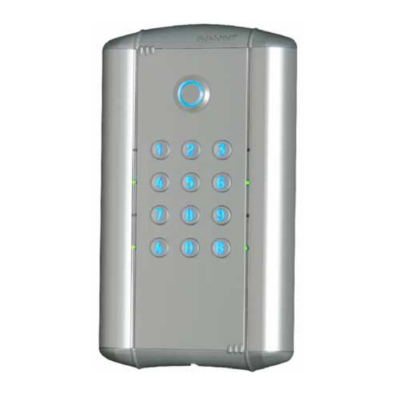
The DC100E keypad exists also in 2 and 3 relay outputs (DC100E2R, DC100E3R). Refer to page 9 of
this manual for information on 2and 3 relay outputs.
The visual feedback with the green and red LED's is always active. It is possible to activate the
audible feedback by putting ST1 jumper on (see page 6).
Qty
Description
1
M5 TORX® spanner
1
05D 680K varistor
Dimensions:
- Face plate: 200 x 120 x 16 (mm)
- Back casing: 170 x 95 x 35 (mm)
DC100E
B
ACK
100
USER CODES
MOUNTING KIT
-
K
K
LIT
EYS
EYPAD
– F
M
LUSH
OUNT
Schéma
G0301FR0235V01
Rating
IP 54
1
Advertisement

Related Manuals for CDVI DC100E


Summary of Contents for CDVI DC100E
- Page 1 LUSH OUNT The DC100E keypad exists also in 2 and 3 relay outputs (DC100E2R, DC100E3R). Refer to page 9 of this manual for information on 2and 3 relay outputs. The visual feedback with the green and red LED’s is always active. It is possible to activate the audible feedback by putting ST1 jumper on (see page 6).
-
Page 2: Product Information
This normally open loop that operates upon activation relay 1 (DC100E, DC100E2R or DC100E3R) or relay 2 (DC100E 2 or 3 relay version). This feature is especially useful when controlling a lock. P1 input activates relay 1 (the time output is programmable). - Page 3 Rev 10/2005 G0301FR0235V01 II. PROGRAMMING A. Erase Keypad Memory / Reset Keypad to Factory Default Values 1. Enter the master code twice (12345 default value master code). 2 beeps are emitted to confirm entry in programming mode. 2. Press A6. The green LED’s lights on during 1 second. Press on A B to start the reset.
- Page 4 Rev 10/2005 G0301FR0235V01 D. A DDING HANGING OR ELETING A Group 1: from user number 00 to user number 99 activate relay 1 1. Enter the master code twice (12345 default value master code). The red LED’s light on to confirm entry in programming mode.
- Page 5 Rev 10/2005 G0301FR0235V01 E. Programming the Time Outputs Enter the master code twice (12345 default value master code). The red LED’s light on to confirm entry in programming mode. 2. Press A0 to program the key-in keypad time and the backlit keys time. The green LED’s light during 1 second.
- Page 6 Rev 10/2005 G0301FR0235V01 Wiring Diagram DC100E: 1 relay output Terminals Description Input Voltage 12 to 24VAC or 12 to 48VDC Input Voltage 12 to 24VAC or 12 to 48VDC Request-to-exit input relay 1 Common input for P1 and H1 Request-to-Enter Input from 0 digit key...
- Page 7 Rev 10/2005 G0301FR0235V01 Wiring Diagram DC100E2R and DC100E3R : 2 and 3 relay outputs Terminals Description Input voltage 12 to 24VAC or 12 to 48 VDC Input voltage 12 to 24VAC or 12 to 48 VDC Relay 1 Request-to-Exit input Common input for P1 and H1 Request-to-Enter Input from 0 digit key (Timed with a timer)
- Page 8 Rev 10/2005 G0301FR0235V01 I. Enable/Disable Audible Feedback The audible feedback is always enabled in programming mode or when the relay is energized. To ENABLE the audible feedback at the press of any key: 1. Enter the master code twice (12345 default value master code). The red LED’s light on to confirm entry in programming mode.
- Page 9 Prepare a cavity in the wall ( to mount the 170H x 95L x 35P) back casing of the DC100E and drill a home for the cable. Seal the back box and make sure to flush mounted it with the wall.
- Page 10 Rev 10/2005 G0301FR0235V01...
- Page 11 Rev 10/2005 G0301FR0235V01 Template Scale 1:1...
Need help?
Do you have a question about the DC100E and is the answer not in the manual?
Questions and answers