Advertisement
Quick Links
Edition 09/2006
The PROFIL100EC keypad is available in 1, 2 or 3 relay output.
Refer to page 8 and 9 for the instructions of version 2 and 3 relay.
Qty
Description
1
M5x8 DIAX
®
1
DIAX
spanner
4
M4x30 screws
4
S5 plastic anchors
1
05D 680K varistor
2
Wiring Sealed caps
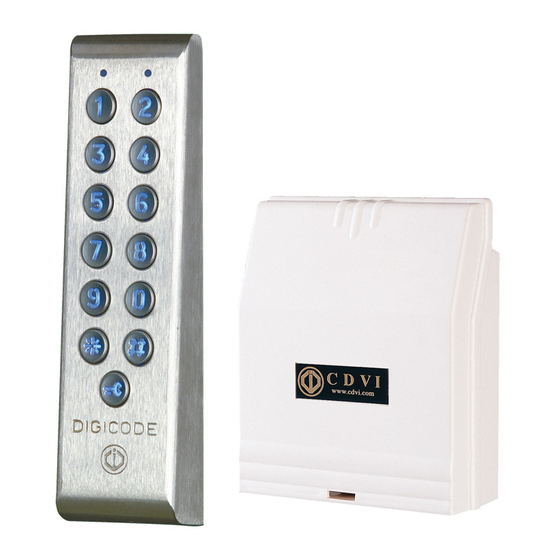
Keypad: 165 x 43 x 27 MM.
Remote Electronics: 147 x 124 x 55 MM.
Illuminated Mullion Stainless Steel Keypad
M OU N TING KIT
®
screws
PROFIL 100 EC
Remote Electronics
Photo
G0301FR0270V01
IP 64
DM
Funtion
Keypad mounting screw
Spanner
2 * keypad
2 * remote electronics
2 * keypad
2 * remote electronics
For the lock
Cable to the remote
controller
1
Advertisement

Related Manuals for CDVI PROFIL 100 EC


Summary of Contents for CDVI PROFIL 100 EC
- Page 1 Edition 09/2006 G0301FR0270V01 PROFIL 100 EC Illuminated Mullion Stainless Steel Keypad Remote Electronics The PROFIL100EC keypad is available in 1, 2 or 3 relay output. Refer to page 8 and 9 for the instructions of version 2 and 3 relay.
-
Page 2: Product Information
Edition 09/2006 G0301FR0270V01 I. PRODUCT INFORMATION A. D 1 relay output version ESCRIPTION 12 – 24 VAC NPUT VOLTAGE FREE VOLTAGE 12 - 48 VDC F NPUT VOLTAGE OLTAGE 12-digit back-lit keypad keys EPROM memory storage 100 Pin code programmables in 4 or 5-digit code 1 relay output N/O &... -
Page 3: Relay Output
Edition 09/2006 G0301FR0270V01 PROFIL100EC 1 IRING IAGRAM RELAY OUTPUT P2: Place jumper for reset P3: Individual Code modification by user V V R1 C1 T1 R2 C2 T2 R3 C3 T3 P1 M P2 Px H H Input voltage 230V 12 to 24 V AC or 12 to 48 VDC Distance 10... - Page 4 Edition 09/2006 G0301FR0270V01 II. PROGRAMMING A. R ESET ASTER ODE AND ELETE ODES Enter the master code twice (12345 default value master code). 2 beeps are emitted to confirm entry in programming mode. 2. Enter *6 to reset the Master Code and the User codes. One beep is emitted. Press simultaneously on * and # digit keys to reset all memory on the keypad.
- Page 5 Edition 09/2006 G0301FR0270V01 3. To Change a user code enter the user number, 4 beeps are emitted to indicate that user location is already programmed. Enter a new 4 or 5-digit code. A beep is emitted to confirm the new user code. 4.
- Page 6 Edition 09/2006 G0301FR0270V01 4. Press # to exit from programming mode. 2 beeps are emitted to confirm that the keypad is in stand-by operating mode. 4 beeps indicate a data computing error. F. R ESET MASTER CODE On stand-by operating mode, put a jumper on P2. Wait 1 second and then remove the jumper. One beep is emitted.
- Page 7 Insert the S5 2 plastic anchors in the holes. Mount the back plate of the PROFIL 100 EC with the M4x30 screws. Insert the cable of the PROFIL 100 EC in the wiring access area. Place the keypad on the back plate top first and then make sure that it fits on the back plate.
- Page 8 Edition 09/2006 G0301FR0270V01 WIRING DIAGRAM PROFIL100 EC 2 and 3 relay outputs P2: Place jumper for reset P3: Individual Code modification by user V V R1 C1 T1 R2 C2 T2 R3 C3 T3 P1 M P2 Px H H Input voltage 230V 12 to 24 V AC...
- Page 9 Edition 09/2006 G0301FR0270V01 J. O PROFIL100 EC 2 PTIONAL RELAY OUTPUTS Programming instructions are the same as for the KCIN keypad with 1 relay output. KCIN 2: 2 relay outputs N/O and N/C contacts 8A @ 250V~ Group 1: from user location 00 to user location 59 to activate relay 1 Group 2: from user location 60 to user location 99 to activate relay 2 Release Time of relay 2 enter *2 sub master code enter *8 (default values 1 and 3).
Need help?
Do you have a question about the PROFIL 100 EC and is the answer not in the manual?
Questions and answers