Table of Contents
Advertisement
Quick Links
North/South America
2700 Mitchell Drive
Walnut Creek
94598 California, USA
Tel: ++(1)9259392400
Fax: ++(1)9259452360 or
++(1)9259452344
© 2009 Varian, Inc. All Rights Reserved
Micro-GC
User Manual
Europe
P.O. Box 8033
4330 EA Middelburg
The Netherlands
Tel: ++(31)118671000
Fax: ++(31)118623193
Printed in the Netherlands
Varian BV
Herculesweg 8
4330 EA Middelburg
The Netherlands
Australia/East Asia
679 Springvale Road
Mulgrave, Victoria 3171
Australia
Tel: ++(61)395607133
Fax: ++(61)395607950
CP501265490 Rev:1 November 2009
Advertisement
Table of Contents

Related Manuals for Varian Micro-GC 490-GC


Summary of Contents for Varian Micro-GC 490-GC
- Page 1 4330 EA Middelburg Mulgrave, Victoria 3171 94598 California, USA The Netherlands Australia Tel: ++(1)9259392400 Tel: ++(31)118671000 Tel: ++(61)395607133 Fax: ++(1)9259452360 or Fax: ++(31)118623193 Fax: ++(61)395607950 ++(1)9259452344 © 2009 Varian, Inc. All Rights Reserved Printed in the Netherlands CP501265490 Rev:1 November 2009...
-
Page 2: Varian Analytical Instrument Warranty
Support Representative to the site or by authorizing the Customer to return the defective accessory or instrument to Varian or to send it to a designated service facility. The Customer shall be responsible for loss or damage in transit and shall prepay shipping cost. -
Page 3: Safety Information
If this manual is not in your native language and if you have problems understanding the text, we advise you to contact your Varian office for assistance. Varian cannot accept responsibility for any damage or injury caused by misunderstanding of the information in this manual. - Page 4 Indicates instrument contains parts that can be damaged by Static discharge electrostatic discharge. Take care for proper grounding Warning before handling. Touching this item may result in damage to the instrument Do not touch or personal injury. Page IV User Manual Micro-GC Varian, Inc.
-
Page 5: General Safety Precautions
It is the responsibility of the Customer to inform Varian Customer Support Representatives if the instrument has been used for the analysis of hazardous biological, radioactive, or toxic samples, prior to any instrument service being performed or when an instrument is being returned to the Service Center for repair. - Page 6 13. Never try to repair or replace any component that is not described in this manual without the assistance of a Varian service engineer. Unauthorized repairs or modifications will result in rejection of warranty claims.
-
Page 7: Spare Parts Availability
Safety Information SPARE PARTS AVAILABILITY SERVICE AVAILABILITY It is the policy of Varian to provide operational spare parts for any instrument and Varian provides a variety of major accessory for a period of seven (7) years after shipment of the final services to support its customers production run of that instrument. -
Page 9: Table Of Contents
Table of contents Table of contents VARIAN ANALYTICAL INSTRUMENT WARRANTY..............II ....................... II ARDWARE RODUCTS ........................ II OFTWARE RODUCTS ........................... II EMEDIES ......................II IMITATION OF ARRANTY ..................II IMITATION OF EMEDIES AND IABILITY SAFETY INFORMATION......................III ..........................III NFORMATION ...................... - Page 10 General functionality ......................39 Micro-GC DMD Channel..................... 41 ........................ 42 ENERAL OPERATION Tuning the DMD........................42 ..........................43 ROTOCOLS Different Types of Protocols: ..................43 The Internet Protocol Suite..................... 43 IP Addresses ........................43 Page 2 User Manual Micro-GC Varian, Inc.
- Page 11 ....................60 ARIAN SERLINK APPLICATIONS External Relays........................60 instrument status including analog inputs................61 UserDataStore addresses of Varian userlink applications ..........61 ........................63 XTERNAL DEVICES CYCLE WITH STATIC (ELECTRONIC) PRESSURE ..............65 CYCLE WITH ELECTRONIC PRESSURE CONTROL.............. 66 COLUMN MODULE CONDITIONING ..................67 BACKFLUSH OPTION .......................
- Page 12 Table of contents SHIPPING INSTRUCTIONS ....................... 71 CLEANING INSTRUCTIONS...................... 71 DISPOSAL INSTRUCTIONS ...................... 71 ERROR LIST..........................72 ........................72 RROR HANDLING : ..........................73 RROR LIST Page 4 User Manual Micro-GC Varian, Inc.
- Page 13 The unique advantages of the allow column head pressure settings to become part of the GC method and can be programmed electronically. The Varian, Inc. Micro-GC with Micro EGC allows you to optimize your analysis. Apart from the constant pressure mode, the Micro EGC in the Micro-GC allows you also to program the pressure over your column.
-
Page 14: Preparing For Installation
Sample pressure between 0 and 100 kPa (1 bar, 15 psi) Outlet of sample container must fit to a stainless steel capillary of 1/16" outside diameter, provided with a Swagelok female nut. ® Page 6 User Manual Micro-GC Varian, Inc. -
Page 15: Micro-Gc Installation
Unpack the Micro-GC and accessories carefully and transfer to the work area, using proper handling techniques. Inspect the Micro-GC and accessories carefully for damage or signs of rough handling. Report damage to the carrier and to your local Varian office. Avoid back strain or injury by following all safety precautions when lifting (heavy) objects. -
Page 16: Packing List
Front and back ferrule 1/16” SS x 2 CP471201 Capillary tubing SS 1/16” x 1.0 mm, 10 cm CP4008 Capillary Ext. Filter CP736879 Power supply 110V or CP49PWR110 Power supply 220V or CP49PWR220 Power supply 240V CP49PWR240 Page 8 User Manual Micro-GC Varian, Inc. -
Page 17: Accessories
Genie 170 BTU filter complete CP739535 Genie 101 BTU filter complete CP739534 Genie 170 standard filter complete CP739536 Genie 170 BTU membrane CP739531 Genie 170 standard membranes 392590004 Genie 101 BTU standard membranes 392590005 Varian, Inc. User Manual Micro-GC Page 9... -
Page 18: Installation
(see front view on page 12). Read chapter Sample Gas on page 16 for more important information! Heated Sample line To connect heated sample lines refer to Heated Sample line chapter on page Page 10 User Manual Micro-GC Varian, Inc. -
Page 19: Connect To Power
If your system is supplied with a DMD (Differential Mobility Detector) detector all settings are factory installed. The complete DMD method for the instrument (customer) specific application is tested en installed inside the DMD. Varian, Inc. User Manual Micro-GC Page 11... -
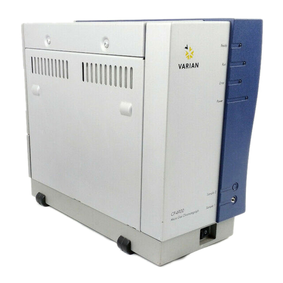
Page 20: Instrument Overview
Led ON: Power OK Led blinking: Voltage < 10 Volt SAMPLE 1 and SAMPLE 2 Sample gas inlet connector See here for more details on page 16 POWER ON/OFF SWITCH Switch the Micro-GC ON or OFF Page 12 User Manual Micro-GC Varian, Inc. -
Page 21: Back View
See here for more details on page 6 CARRIER 1 CONNECTOR POWER CONNECTOR Carrier gas input connector Power IN connector (male). See here for more details on page 15. See here for more details on page 20 Varian, Inc. User Manual Micro-GC Page 13... -
Page 22: Inside View
See here for more details on page 37 ANALOG I/O External Analog I/O signals. See here for more details on page 38 DIGITAL I/O Digital in and output signals. See here for more details on page 36 Page 14 User Manual Micro-GC Varian, Inc. -
Page 23: Carrier Gas Connection
Micro-GC (use an electronic Leak Tester). CP-Gas Clean filters are filled with nitrogen. If you are not using nitrogen as the carrier gas, flush filters and gas lines after installation of a new filter. Varian, Inc. User Manual Micro-GC Page 15... -
Page 24: Sample Gas
Sample pressure should be between 0-100 kPa (0-15 psi), the temperature between 0 and 40C ± 5°C of the analyzer ambient temperature and it must be filtered, preferably through a 5 m filter. Varian, Inc. ALWAYS recommends the use of the external filter kit part number CP736729. -
Page 25: Heated Injector Systems
Introduction and Initial Operation Heated Injector Systems Varian, Inc. User Manual Micro-GC Page 17... -
Page 26: Heated Sample Line
Open the side panel, the heater will be visible. Remove the insulation. Sample line heater The sample line connector will be visible. Connect the sample line. Page 18 User Manual Micro-GC Varian, Inc. - Page 27 Introduction and Initial Operation Insulate the sample line coming into the Micro-GC, this to prevent damage to the in/out coming cables. Must be insulated! Varian, Inc. User Manual Micro-GC Page 19...
-
Page 28: Power
Remove the carrier gas tubing and plug all the vents/carrier gas connections with 1/8” brass nut or plastic cap. When the instrument is going to be used again then follow the procedure on page 21 Page 20 User Manual Micro-GC Varian, Inc. -
Page 29: Long Storage Recovery Procedure
Set the column(s) temperature to the maximum allowed temperature. Condition the column module, preferably overnight. This will ensure that all the water has been removed from the column module and no damage will occur to the TCD filaments. Varian, Inc. User Manual Micro-GC Page 21... -
Page 30: Initial Operation
CP-Sil 5 CB and CP-Sil 19 0.007 % Isopentane CB, HayeSep A and Molsieve. The sample is 0.001 % N-pentane natural gas, which provides a convenient standard for testing the instrument in any configuration of these columns. Page 22 User Manual Micro-GC Varian, Inc. -
Page 31: Column Cp-Sil 5 Cb 6 Meter Unheated
CP-Sil CB columns. Nitrogen, methane, carbon dioxide, and ethane are not separated on these columns. They produce a composite peak. For separation of these components a HayeSep A column is advised. Varian, Inc. User Manual Micro-GC Page 23... -
Page 32: Column Cp-Sil 5 Cb 4 Meter Heated
: 150kPa (21PSI) Sample time : 30s Injection time : 40ms Run time : 30s Detector sensitivity : Auto Peak identification Component Concentration Composite Balance Ethane 8.1% Propane 1.0% i-Butane 0.14% n-Butane 0.20% Page 24 User Manual Micro-GC Varian, Inc. -
Page 33: Column Cp-Sil 5 Cb 8 Meter Heated
: 150kPa (21PSI) Sample time : 30s Injection time : 40ms Run time : 60s Detector sensitivity : Auto Peak identification Component Concentration Composite Balance Ethane 8.1% Propane 1.0% i-Butane 0.14% n-Butane 0.20% Varian, Inc. User Manual Micro-GC Page 25... -
Page 34: Column Cp Sil13Cb Tbm 12 Meter Heated
Column temperature : 40°C Component Concentration Injector temperature : 50°C Methane Balance Column pressure : 250kPa (38PSI) 6.5ppm Sample time : 30s Injection time : 255ms Run time : 80s Detector sensitivity : Auto Page 26 User Manual Micro-GC Varian, Inc. -
Page 35: Column Hayesep 40Cm Heated
The HaySep A column separates oxygen, methane, carbon dioxide, ethane, acetylene, ethylene, and selected sulfur gases. Nitrogen coelutes with oxygen. Components with a higher molecular weight than propane have long retention times on this column. Maximum allowable column temperature: 160 C Varian, Inc. User Manual Micro-GC Page 27... -
Page 36: Column Molsieve 5Å 20 Meter Unheated
Detector sensitivity : Auto The Molsieve 5Å column is designed to separate: hydrogen, carbon monoxide, methane, nitrogen, oxygen, and some noble gases. Higher molecular weight components have much higher retention times on this column. Page 28 User Manual Micro-GC Varian, Inc. -
Page 37: Conditioning Of Molsieve Columns
180C overnight. The longer the re+onditioning period the better the column performance without damage. Varian, Inc. User Manual Micro-GC Page 29... -
Page 38: Column Ppq 10 Meter Heated
: 110°C Composite Balance Column pressure : 150kPa (21PSI) Ethane 8.1% Sample time : 30s Propane 1.0% Injection time : 40ms i-Butane 0.14% Run time : 50s n-Butane 0.20% Detector sensitivity : Auto Page 30 User Manual Micro-GC Varian, Inc. -
Page 39: Reference
Reference REFERENCE INSTRUMENT DESCRIPTION CARRIER GAS The Varian, Inc. Micro-GC is configured for the use with either He (or H ) or N (or Ar). Having chosen one option definitely rules out the use of the other without the instrument undergoing internal changes prior to any switching of carrier gas type. -
Page 40: Micro Electronic Gas Control (Egc)
200 nL. Injection time will be rounded to a multiple of 5 ms. A practical minimum value is 40 ms. In most cases a value of 0 - 20 milliseconds will result in no injection. Page 32 User Manual Micro-GC Varian, Inc. -
Page 41: Column
MES column ppm) For all compounds not present in this list contact you nearest Varian office All columns except the HayeSep A (160 C) and MES (110 C) (TCEP) column can be used up to 180 C, the maximum temperature of the column oven. The HayeSep A will deteriorate above 160 C. -
Page 42: Detector
Differential Mobility Detection is an advanced form of Ion Mobility Spectroscopy (IMS). It uses a drift tube under atmospheric and thermally constant conditions. See for more details chapter The difference mobility detector on page Page 34 User Manual Micro-GC Varian, Inc. -
Page 43: In/Outputs
The Micro-GC has several in/output ports accessible inside the instrument for interfacing with external devices. Open the cover. At the front of the Micro-GC, the external device connectors will be visible. Close the cover after connecting the cables! Varian, Inc. User Manual Micro-GC Page 35... -
Page 44: External Digital I/O
+12 VDC out ( electronic fused max 500 mA) External Digital I/O Relay contacts maximum 24 Volt 1 Ampere Ready/not ready signal The Instrument Ready/not Ready output will follow instrument status (Ready LED in the front of the instrument). Page 36 User Manual Micro-GC Varian, Inc. -
Page 45: Communication Ports (Com)
RS-232 RS-232 COM 3 RXA(+) RXB(-) TXB(-) TXA(+) RS-485 Varian, Inc. User Manual Micro-GC Page 37... -
Page 46: External Analog I/O
+15 VDC out (electronic fused max 100 mA) -15 VDC out (electronic fused max 100 mA) +5 VDC out (electronic fused max 500 mA) +12 VDC out (electronic fused max 500 mA) Analog GND External Analog I/O Page 38 User Manual Micro-GC Varian, Inc. -
Page 47: The Differential Mobility Detector
Ni Radiation Safety Manual. General functionality Varian has extended its Micro Gas Chromatography product line with a new detector. The Differential Mobility Detector, DMD, integrated into the chassis is a joint development of Sionex Corporation and Varian Instruments. - Page 48 As illustrated in Figure 1, the net voltage applied results from three independent settings: 1. A fixed voltage, or RF-Voltage, 2. A scanning voltage, also referred to as Compensation Voltage, A RF modulated voltage. Page 40 User Manual Micro-GC Varian, Inc.
-
Page 49: Micro-Gc Dmd Channel
The DMD channel is always located in the last position (against the backpanel) Position 2 DMD channel The firmware recognises the DMD channel as a detector only, and automatically sets the controls accordingly. Varian, Inc. User Manual Micro-GC Page 41... -
Page 50: General Operation
In case of a suspected misalignment of the method, where retention time or compensation voltage may be out of tune, a tuning run may be needed. Please contact for more information your local Varian Inc. subsidiary or Varian, Inc. representative. -
Page 51: Protocols
Each part of an IP address can only be in that range (e.g., 198.12.253.98). The Internet protocol suite Starting IP Ending IP Subnet Mask Type 0.0.0.0 255.255.255.255 Public 10.0.0.0 10.255.255.255 255.0.0.0 Private 172.16.0.0 172.31.255.255 255.255.0.0 Private 192.168.0.0 192.168.255.255 255.255.0.0 Private Note: never use 0.0.0.0. or 255.255.255.255 Varian, Inc. User Manual Micro-GC Page 43... -
Page 52: Micro-Gc And Networks
Q: Can I control my Micro-GC from anywhere in the world via the Internet? A: Yes, if the customer network is designed for this, and has Internet access or remote access facilities (the ports 4900,4901 and 4902 must be open). Page 44 User Manual Micro-GC Varian, Inc. -
Page 53: Glossary Of Network Terms
(between 1 and 255) that provide routing information used by the TCP/IP protocol to establish a reliable connection. Without the IP Address, communications would be bogged down trying to establish connections to Ethernet addresses at unknown locations. Varian, Inc. User Manual Micro-GC Page 45... -
Page 54: Patch Cable
TCP/IP An international standard protocol used by the Internet. We use this protocol for communication to the Micro-GC. You may find several network protocols, such as IPX/SPX and NetBEUI, installed on you computer. Page 46 User Manual Micro-GC Varian, Inc. -
Page 55: Workstation Software
External start in: Yes Digital I/O External Ready: Yes External Ready: Yes Timed Relay: Yes Timed Relay: Yes Relay Control Alarm Relay: Yes Alarm Relay: Yes Only one Vici valve possible in Galaxie Varian, Inc. User Manual Micro-GC Page 47... -
Page 56: Ezchrom Elite
In that case the instrument will accept the first incoming connection type (serial or Ethernet) and will lock the other connection type. There can never be a connection on the two different ports at the same time. Page 48 User Manual Micro-GC Varian, Inc. -
Page 57: Serial Communication
RS485 is only possible via two RS232-RS485 converters, one on Workstation (computer) side and either one at Micro-GC side on Com 1. Com 1 Com 1: RS232 Serial Cable Com 2: RS232 Serial Cable EZChrom Elite 490-GC Com 1 490-GC Varian, Inc. User Manual Micro-GC Page 49... -
Page 58: Ethernet Communication
Micro-GC both to a (local) network. Peer-to-peer: single instrument Crossover Cable Workstation Any IP-address allowed 490-GC Multiple 490-GCs connected to a local workstation. IP-address in same range as computer IP-address. Page 50 User Manual Micro-GC Varian, Inc. -
Page 59: Multiple Instrument (Local Network)
Workstation Any IP-address allowed EZChrom Elite maximum connections are limited by the computer speed, license and network performance. 490-GC Multiple 490-GCs connected to a local workstation. IP-address in same range as computer IP-address. Varian, Inc. User Manual Micro-GC Page 51... -
Page 60: Global Network: Multiple Instruments
IP-address in same range of subnet 1. Switch Subnet 2 EZChrom Elite IP-address in range of IP-address in range of subnet 2 subnet 2 490-GC in subnet 1 can also be controlled Page 52 User Manual Micro-GC Varian, Inc. -
Page 61: Communication Setup
(and in the right subnet range) only the IP address has to be typed in. It’s also possible to change the IP address (Assign new IP address on page 54) with BootP and to view all the Micro-GCs connected to the subnet. Varian, Inc. User Manual Micro-GC Page 53... -
Page 62: Assign New Ip Address Via Ethernet Connection
10. Switch the Micro-GC off and then on again (Reboot). Never startup two Micro-GCs in the assign IP-address service mode at the same time. This to avoid assigning an IP address to the wrong Micro-GC. Page 54 User Manual Micro-GC Varian, Inc. -
Page 63: Assign New Ip Address Via Serial Connection
8. Switch the Micro-GC off and then on again (Reboot). 9. Change the Micro-GC configuration from Serial mode to Ethernet mode and proceed as described in the section Ethernet communication on page Varian, Inc. User Manual Micro-GC Page 55... -
Page 64: Remote Access Instrument Status
Reference REMOTE ACCESS INSTRUMENT STATUS The Instrument status of the Micro-GC can be accessible for other applications like Varian userlink applications: Mlink32, I/O Control, PCI1000Com or any other self written program capable to collect instrument status from the UserDataStore database. - Page 65 Injector temperature channel 4 in Celsius 1251 Column pressure channel 1 in kPa 1252 Column pressure channel 2 in kPa 1253 Column pressure channel 3 in kPa 1254 Column pressure channel 4 in kPa Varian, Inc. User Manual Micro-GC Page 57...
-
Page 66: General Error State
TCD calibration failed Hardware reset" Pressure too high Initialization error Internal communication error Instrument EDS incorrect EDS incorrect Internal power failure Flush cycle aborted GC module changed TCD Gain calibrated TCD Offset calibrated Null String Page 58 User Manual Micro-GC Varian, Inc. - Page 67 DMD sensor voltage error DMD RF voltage error DMD Vc voltage error DMD sensor pressure error DMD tuning process error DMD gas flow error DMD system voltage error DMD communication error DMD sensor error Varian, Inc. User Manual Micro-GC Page 59...
-
Page 68: Varian Userlink Applications
Everything stored in the shared UserDataStore database can be used to setup a switch condition, since every Varian userlink application is capable to store its specific results into this database. To store CP-Maitre Elite 3.2 concentrations into the UserDataStore database look at topic Common Tab of Instrument Method Setup. -
Page 69: Instrument Status Including Analog Inputs
UserDataStore addresses of Varian userlink applications Find below a table of relevant UserDataStore addresses, which can be used, for alarming purposes. The addresses are all part of the Varian Userlink applications: ISOCAL32, BTU32, InstrumentNorm32 and Mlink32. The addresses are specific for each instrument (maximal four instruments) - Page 70 Stream Position from CP-Maitre Elite Total ESTD summed of all channels EliteExport.dll or Mlink32 520 and User defined parameters as defined in the UserDataStore sheets output section of Mlink32 or as defined in the EliteExport.ini file. Page 62 User Manual Micro-GC Varian, Inc.
-
Page 71: External Devices
External_digital_IO 7. Six External Analog Input signals The driver supports the acquisition and processing of the External Analog Input signals (see also External_Analog_IO on page 36). The VICI electric actuated multi positional valve Varian, Inc. User Manual Micro-GC Page 63... - Page 72 Reference Page 64 User Manual Micro-GC Varian, Inc.
-
Page 73: Cycle With Static (Electronic) Pressure
The Workstationsoftware will time allows the acquisition is run is finished. be downloaded wait until data is received sample to settle in started. via the from the Micro-GC. the sample-loop Workstation Varian, Inc. User Manual Micro-GC Page 65... -
Page 74: Cycle With Electronic Pressure Control
The pressure from the final pressure to the initial same. remains the same. pressure. Varian, Inc. User Manual Micro-GC Page 66... -
Page 75: Column Module Conditioning
3. Download this method to the Micro-GC. 4. Condition the column module, preferably overnight. This will insure you that all the “water” has been removed from the column module and no damage will occur to the TCD filaments. Varian, Inc. User Manual Micro-GC Page 67... -
Page 76: Backflush Option
The Varian Micro-GC is optionally available with GC modules that incorporate backflush capabilities. A backflush system always consists of a pre-column and an analytical column. -
Page 77: Description
(back) flushed to the vent (see backflush diagram). On the analytical column the separation goes on, because as there the flow is not inverted! Varian, Inc. User Manual Micro-GC Page 69... -
Page 78: Tuning
Be aware that a small pre-column is used. It is not always possible to cut between 2 peaks! Backflush Time range 0.5 seconds until maximum run time. Special value BACKFLUSH TIME = 0 this puts the system in FOREFLUSH mode during run the entire run. Page 70 User Manual Micro-GC Varian, Inc. -
Page 79: Shipping Instructions
When the lifetime of the Micro-GC or parts of it has reached the end of its useful life, disposal must be carried out in accordance with all (environment) regulations applicable in your country. Varian, Inc. User Manual Micro-GC Page 71... -
Page 80: Error List
(trouble shooting information) under instrument status. All Class 1 and above errors will be logged on flash. Individual numbers identify all errors; these numbers are built using the error class and a number. Events are not numbered. Page 72 User Manual Micro-GC Varian, Inc. -
Page 81: Error List
Instrument EDS incorrect Instrument Electronic Datasheet incorrect Call service EDS incorrect Electronic Datasheet incorrect Call service Internal power failure During/after initialization, internal supplies Call service Flush cycle aborted Flush cycle stopped before completion Varian, Inc. User Manual Micro-GC Page 73... - Page 82 Column cleaning Instrument in column cleaning state Instrument stabilizing after column cleaning Equilibrating temperature zones Wait till Ready DMD control to temperature Wait for Notification that DMD is warming up. setpoint completion Page 74 User Manual Micro-GC Varian, Inc.
- Page 83 Internal Software Error, IOC fatal error 1 Auto reboot Watchdog Error: IOC Fatal error Internal Software Error, IOC fatal error 2 Auto reboot Watchdog Error: IOC Fatal error Internal Software Error, IOC fatal error 3 Auto reboot Varian, Inc. User Manual Micro-GC Page 75...
Need help?
Do you have a question about the Micro-GC 490-GC and is the answer not in the manual?
Questions and answers