Table of Contents
Advertisement
Quick Links
R50
ITALIANO pag. 04 / FRANÇAIS pag. 14 / ENGLISH page 24 / DEUTSCH pag. 34
Operatore
Alimentazione
Operateur
Alimentation
Operator
Power Supply
Torantrieb
Stromspannung
R50
230V 50/60Hz
OPERATORE PER PORTONI INDUSTRIALI
OPERATEUR POUR PORTAILS INDUSTRIELS
OPERATOR FOR INDUSTRIAL DOORS
TORANTRIEB FÜR INDUSTRIETORE
Peso max cancello
Poids maxi portail
Max gate weight
Max Torgewicht
2000 kg / 4460 lbs
codice
code
code
code
AA21580
Advertisement
Table of Contents

Related Manuals for RIB R50


Summary of Contents for RIB R50
- Page 1 OPERATORE PER PORTONI INDUSTRIALI OPERATEUR POUR PORTAILS INDUSTRIELS OPERATOR FOR INDUSTRIAL DOORS TORANTRIEB FÜR INDUSTRIETORE Operatore Alimentazione Peso max cancello codice Operateur Alimentation Poids maxi portail code Operator Power Supply Max gate weight code Torantrieb Stromspannung Max Torgewicht code 230V 50/60Hz 2000 kg / 4460 lbs AA21580 ITALIANO pag.
- Page 2 Die in diesem Handbuch aufgeführten Daten sind ausschließlich empfohlene N.B.: The system must be grounded Werte. RIB behält sich das Recht vor, das Produkt zu jedem Zeitpunkt zu Data described by this manual are only Indicative and RIB reserves modifizieren. Die Anlage muss in Übereinstimmung mit den gültigen Normen to modify them at any time.
-
Page 3: Technical Features
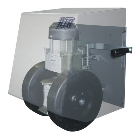
ECHNICAL FEATURES Gearmotor for operating industrial swing gates with overall maximum weight of 2000 kg. The R50 is an irreversible electric gearmotor with adjustable drive force, regulated by changing the pressure exerted by the drive wheels on the ground. The drive wheels are able to run over surface irregularities of up to 6 cm (approx.), because the gearmotor unit slides along... -
Page 4: Pre-Installation Checks
COMMAND TYPE USE OF THE SHUTTER flexible during the movement and must move without frictions. The Skilled persons Skilled persons Unrestricted use ground on which the R50 wheels run must be solid and compact with (out of public area*) (public area) minimum gradient. with manned operation non possibile Gate features must be uniformed with the standards and laws in with visible impulses force. -
Page 5: Emergency Release
50 APPLICATION ON MULTIPLE PANEL DOORS In this case the R50 must be installed on the first leaf. Olive Limit switch Wheels Ø120 Internal Limit switch Guide Mechanical stopper External MERGENCY RELEASE To be undertaken after disconnecting power supply. In the event of a power failure, raise the side handle to lift the wheels off the ground. -
Page 6: Electrical Safety Devices
LECTRICAL SAFETY DEVICES AINTENANCE The installation must be installed according to the current regulations To be undertaken by specialized staff after disconnecting power and laws. supply. Use the T2 electronic control unit. Clean the wheel contact surfaces carefully once a week. For connections and technical data of accessories refer to the Check wheel/ground pressure and condition of motor wheels every six appropriate booklets. -
Page 7: Control Panel Features
OTHERWISE THE OPERATOR WILL NOT WORK! PROBE Not available for R50 RADIO Built-in radio module (model CRX), or connector for radio receiver RIB, 12 Vdc supply To select 1 motor (M1) or 2 motors (M1 and M2) JP17 PROG Programming button... - Page 8 OFF - safety strip self-test DISABLED 1 - The gate must be fully closed. 2 - Turn DIP2 to ON position, LED DL1 starts blinking DIP 14 OFF OBLIGATORY FOR R50 MOTOR 3 - Press PROG. Button, motor M1 opens. DIP 15 ON...
- Page 9 DIP3 function to enable or disable the Automatic Closing feature). briefly. The red DL1 LED will stop flashing. 6 - The LED DL1 will turn OFF, indicating exit from the Point E procedure. Closing of 6 - Reposition DIP 1 to OFF and DIP 3 to OFF. the gate will be carried out at normal speed and only on approaching total closing at N.B: IF THE DL1 LED CONTINUES TO FLASH RAPIDLY, THIS MEANS THAT low speed (depending on the adjustment of LOW SPEED trimmer).
- Page 10 a pedestrian crossing. In fact, the Pedestrian command (see Point F) is carried out - close the gate as soon as the vehicle leaves the photocell beam. only by opening the motor M1 just enough for a pedestrian to pass, as described into If DIP12 ON and DIP4 OFF the Point F procedure.
- Page 11 The DIP 5 in the OFF position disables any pre-flashing, the BLINKER starts flashing ECHNICAL SPECIFICATIONS and the motors will start at the same time. - Humidity < 95% without BUZZER condensation The current supplied to the Buzzer will be 200 mA at 12Vdc. - Power supply voltage 230 o 120V~ ±10% During the normal operation of the gate, opening and closing, the buzzer will buzz...
-
Page 12: Electric Lock
For the connections and the technical data of the optional equipments follow the relevant ACCESSORIES - handbooks. ADIO TRANSMITTER SUN IT SYNCRO SUN 2CH code ACG6052 SUN 4CH code ACG6054 SUN CLONE 2CH code ACG6056 SUN CLONE 4CH code ACG6058 FIT SYNCRO PHOTOCELLS for the wall-installation code ACG8026 The range you can set is 10-20 m, 30÷60ft. - Page 13 Timone regolab. R50 CTC1402 Paraolio30x47x7 CCA1301 CME8047 Squadretta di guida R50 CCA1214 dal 09-2010 Piastra di base CME8200 Leva di sblocco manuale R50 CVA1029 Manopola MCG 28 85 GIR CCA1302 CME8997 Vite senza fine CVA1380 Copriventola motore CCA1375 dal 09-2010 Carter...
Need help?
Do you have a question about the R50 and is the answer not in the manual?
Questions and answers