Table of Contents
Advertisement
Available languages
Available languages
Quick Links
R50
ITALIANO pag. 04 / FRANÇAIS pag. 14 / ENGLISH page 24 / DEUTSCH pag. 34
Operatore
Alimentazione
Operateur
Alimentation
Operator
Power Supply
Torantrieb
Stromspannung
Operador
Alimentacion
R50
230V 50/60Hz
con / avec / with / mit
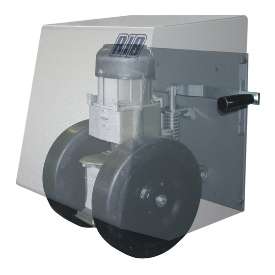
OPERATORE PER PORTONI INDUSTRIALI
OPERATEUR POUR PORTAILS INDUSTRIELS
OPERATOR FOR INDUSTRIAL DOORS
TORANTRIEB FÜR INDUSTRIETORE
Peso max cancello
Poids maxi portail
Max gate weight
Max Torgewicht
Peso máx verja
2000 kg / 4460 lbs
1
Codice
Code
Code
Kode
Codigo
AA21580
T2
Advertisement
Table of Contents

Related Manuals for RIB R50 RIB


Summary of Contents for RIB R50 RIB
- Page 1 con / avec / with / mit OPERATORE PER PORTONI INDUSTRIALI OPERATEUR POUR PORTAILS INDUSTRIELS OPERATOR FOR INDUSTRIAL DOORS TORANTRIEB FÜR INDUSTRIETORE Operatore Alimentazione Peso max cancello Codice Operateur Alimentation Poids maxi portail Code Operator Power Supply Max gate weight Code Torantrieb Stromspannung...
- Page 2 à clé). 2° - Per la sezione ed il tipo dei cavi la RIB consiglia di utilizzare un cavo di tipo 2° - En ce qui concerne la section et le type des câbles, RIB conseille d’utiliser un câble...
-
Page 3: Installation
(z.B.mit einen Schluesselkatsten in einem Panzergehaeuse). 2° - For the section and the type of the cables RIB advices to use a cable of H05RN-F 2° - RIB empfiehlt den Kabeltyp H05RN-F mit einem minimalen Querschnitt von 1,5 mm... - Page 5 LAYOUT IMPIANTO CARATTERISTICHE TECNICHE Operatore per movimentare portoni a battente ad uso industriale del peso massimo complessivo di 2000 kg. R50 è un operatore irreversibile la cui forza di traino è variabile con la pressione, regolabile, che le ruote motrici esercitano sul pavimento. Le ruote motrici che aderiscono al terreno hanno la possibilità...
- Page 6 INSTALLAZIONE R50 Componenti da installare secondo la norma EN12453 CONTROLLO PRE-INSTALLAZIONE USO DELLA CHIUSURA Le ante devono essere solidamente fissate ai cardini delle colonne, non devono flettere durante il movimento e devono muoversi senza attriti. Persone esperte TIPO DI COMANDO Persone esperte Il terreno sul quale vanno ad agire le ruote dell’R50 deve essere compatto, non friabile e (fuori da area...
- Page 7 APPLICAZIONE DELL’R50 A PORTONE CON PIÙ ANTE SCORREVOLI In questo caso l’R50 dovrà essere montato sulla prima anta Olive Finecorsa Ruote Ø120 Interno Finecorsa Guida Fermo meccanico Esterno SBLOCCO DI EMERGENZA Da effettuare dopo aver tolto l’alimentazione elettrica al motore. In caso di mancanza di energia elettrica sollevare la maniglia laterale per ottenere il sollevamento delle ruote dal terreno.
-
Page 8: Manutenzione
Contatto comando apertura pedonale (NA) RADIO Modulo radio incorporato (modello CRX), o connettore per radio Comune dei contatti ricevitore RIB ad innesto con alimentazione a 24 Vdc. LOCK Collegamento elettroserratura (MAX 15W 12V) JP17 Selezione funzionamento con 1 o 2 motori... - Page 9 LAMPEGGIATORE MOTOR 2 CONDENSATORE M2 ANTENNA CALZA CONDENSATORE M1 MOTOR 1 ANTENNA R=2,2K SPIA BUZZER 24Vdc per AUTOTEST PER COSTA 24Vdc per ACCESSORI FOTOCELLULE ALIMENTAZIONE COSTE 230Vac 50 Hz PASSO PASSO PEDONALE COMUNE SERRATURA ELETTRICA B - MICROINTERRUTTORI DI GESTIONE JP 17 Selezione funzionamento con 1 o 2 motori (di default jumper chiuso 2 motori) JP1 =>...
- Page 10 SEGNALAZIONI LED 4 - Raggiunto il fermo meccanico di apertura, dopo un secondo premete il pulsante DL1 - (Rosso) - Programmazione attivata PROG. => M1 si ferma e si attiva il conteggio del tempo d’attesa prima della chiusura DL2 - (Verde) - Programmazione radio attivata (solo nei modelli CRX) automatica (max 5 minuti).
- Page 11 La programmazione può essere eseguita solo a cancello fermo. Ad automazione aperta vengono inibite tutte le funzioni di comando. 1 - Posizionare DIP 1 su ON e successivamente il DIP 3 su ON. Se la chiusura automatica è attiva, rilasciando l’interruttore, o allo scadere dell’ora impostata, 2 - Il led rosso DL1 di programmazione lampeggia con frequenza di 1 sec.
-
Page 12: Caratteristiche Tecniche
ATTENZIONE: Se il led del ricevitore rimane acceso è possibile che siano presenti dei Durante il funzionamento a uomo presente tenere premuto K BUTTON o PED. BUTTON per disturbi sulla rete di alimentazione. l’intera manovra fino allo spegnimento dei relativi led motori (DL3 - DL5 apertura totale Vi consigliamo di collegare elettricamente a terra le M2 - M1 - pedonale DL5 - DL4 - DL6 chiusura totale M2 - M1 - pedonale DL6) o del 24Vdc... -
Page 13: Risoluzione Problemi
- Tempo eccitazione 300ms Dopo aver effettuato tutti i collegamenti seguendo attentamente lo schema ed aver - Tempo diseccitazione 300ms posizionato il cancello in posizione intermedia, verificare la corretta accensione dei led DL7, - Codici memorizzabili N° 62 totali DL8. In caso di mancata accensione dei led, sempre con cancello in posizione intermedia, - Tutti gli ingressi devono essere utilizzati come contatti puliti perchè... - Page 14 FIT SLIM SPARK Per ottenere le migliori prestazioni degli apparati sopracitati, bisogna installare un’antenna accordata sulla frequenza del radio ricevitore installato . FOTOCELLULE DA PARETE cod. ACG8032 N.B. Fare molta attenzione che il filo centrale del cavo non vada a contatto con la COPPIA DI COLONNINE PER FIT SLIM cod.
-
Page 15: Caracteristiques Techniques
SCHÉMA DÉTAILLÉ DE L’INSTALLATION CARACTERISTIQUES TECHNIQUES Motoréducteur pour portails à vantaux industriels d’un poids total maximum de 2000 kg. Le R50 est un motoréducteur irréversible dont la force d’entraînement varie en fonction de la pression (réglable) exercée sur le sol par les roues motrices. Les roues motrices, qui adhèrent au sol, peuvent supporter un dénivellement d’environ 3 cm, puisque le motoréducteur coulisse sur une glissière verticale. - Page 16 INSTALLATION R50 CONTROLE PRE-INSTALLATION Parties à installer conformément à la norme EN12453 Le portail à battant doit être solidement fixé aux cardans des colonnes, ne doit pas flechir USAGE DE LA FERMETURE pendant le mouvement et doit pouvoir manoeuvrer sans effort. Le terrain sur lequel se Personne expertes déplace le roues du R50 doit être compact, non friable et avec une très faible pente.
- Page 17 APPLICATION DU R50 A UN PORTAIL A PLUSIEURS VANTAUX COULISSANTS Dans ce cas, le R50 devra être monté sur le premier vantail. Olive Fins de course Roues Ø120 Intérieur Finecorsa Guide Farret mécanique Extérieur DEBLOCAGE D’URGENCE Effectuer apres avoir coupé l’alimentation. En cas de coupure de courant, tirez la poignée latérale vers le haut pour soulever les roues du sol.
-
Page 18: Entretien
SECURITES ELECTRIQUES ENTRETIEN Adapter les installation du parties electriques aux normes et lois en vigueur. Nous vous Effectuer seulement par personnel specialisé apres avoir coupé l’alimentation. conseillons d’utiliser un coffret électronique T2. Chaque fin de semaine, nettoyez soigneusement la surface de glissement des roues. Pour ce qui est des raccordements et des données techniques des accessoires, se référer Tous les six mois, contrôlez la pression de le roues sur le sol et contrôlez l’état de le à... - Page 19 NE PAS TOUCHER AU CAVALIER ! - SANS L’OPÉRATEUR, IL NE FONCTIONNE PAS! RADIO Module radio incorporé (modèle CRX) ou connecteur pour radio récepteur RIB à raccord avec alimentation à 24 Vdc. SW T2 JP17 Sélection fonctionnement avec 1 ou 2 moteurs SW RADIO NE PAS TOUCHER AU CAVALIER ! - SI LE SYSTÈME RADIO EST...
- Page 20 DL2 - (Vert) - Programmation radio activée (seulement dans les modèles CRX) 5 - Appuyez sur le bouton-poussoir PROG. => le comptage du temps d’attente avant la DL3 - (Vert) - Portail en ouverture M2 fermeture automatique s’arrête et M1 ferme. Au même moment, le voyant DEL DL1 DL4 - (Rouge) - Portail en fermeture M2 cessera de clignoter en signalant la sortie de la procédure d’acquisition.
- Page 21 mémoriser la télécommande suivante. durant le mouvement de fermeture, elle le fait ouvrir de nouveau. 5 - Pour terminer la programmation, laisser s>écouler 10 sec., ou bien appuyer pendant un FERMETURE AUTOMATIQUE (TOTALE) instant sur le bouton PROG. La led rouge DL1 de programmation arrête de clignoter. 6 - Replacer DIP 1 sur OFF et DIP 3 sur OFF.
- Page 22 portail se ferme. DIP 12 ON et DIP 4 ON => Comme le portail s’ouvre, en passant devant les photocellules, FONCTION PRÉ-CLIGNOTEMENT DIP 5 - OFF => le moteur, le clignotant et le vibreur sonore partent en même temps. le portail continue à s’ouvrir. Terminé de transit, le portail s’arrête et après 1 seconde de pause il invertit le mouvement DIP 5 - ON =>...
-
Page 23: Solution Des Problemes
éteinte Bande de contact de sécurité en panne (Si la bande de contact n’est pas reliée, effectuer la connexion entre COM et EDGE) SOLUTION DES PROBLEMES Durant le fonctionnement avec opérateur présent, avec DIP n° 1 sur ON, vérifier que durant Après avoir effectué... - Page 24 SPARK FIT SLIM Afin d’optimaliser les performances des appareils suscités, il est indispensable d’installer une antenne accordée sur la fréquence du radiorécepteur installé. PHOTOCELLULES MURALES code ACG8032 N.B. Veiller à ce que le fil central du câble n’entre pas en contact avec l’enveloppe PAIRE DE POTEAUX POUR FIT SLIM code ACG8065 extérieure en cuivre;...
-
Page 25: System Layout
SYSTEM LAY-OUT TECHNICAL FEATURES Gearmotor for operating industrial swing gates with overall maximum weight of 2000 kg. The R50 is an irreversible electric gearmotor with adjustable drive force, regulated by changing the pressure exerted by the drive wheels on the ground. The drive wheels are able to run over surface irregularities of up to 3 cm (approx.), because the gearmotor unit slides along a vertical track. -
Page 26: Pre-Installation Checks
R50 INSTALLATION Parts to install meeting the EN 12453 standard PRE-INSTALLATION CHECKS USE OF THE SHUTTER The leaf must be fixed firmily on the hinges to the pillars, must not be flexible during the Skilled persons COMMAND TYPE movement and must move without frictions. The ground on which the R50 wheels run must be Skilled persons (out of public Unrestricted use... -
Page 27: Emergency Release
R50 APPLICATION ON MULTIPLE PANEL DOORS In this case the R50 must be installed on the first leaf. Olive Limit switch Wheels Ø120 Internal Limit switch Guide Mechanical stopper External EMERGENCY RELEASE To be undertaken after disconnecting power supply. In the event of a power failure, raise the side handle to lift the wheels off the ground. In order to carry out the manual operation of the gate leaf the followings must be checked: - That the gate is endowed with appropriate handles;... -
Page 28: Maintenance
ELECTRICAL SAFETY DEVICES MAINTENANCE The installation must be installed according to the current regulations and laws. To be undertaken by specialized staff after disconnecting power supply. Use the T2 electronic control unit. Clean the wheel contact surfaces carefully once a week. For connections and technical data of accessories refer to the appropriate booklets. - Page 29 WILL NOT WORK! RADIO Built-in radio module (model CRX), or connector for radio SW T2 receiver RIB, 24 Vdc supply SW RADIO DO NOT REMOVE ANY JUMPER! - OTHERWISE THE OPERATOR JP17 To select 1 motor (M1) or 2 motors (M1 and M2)
- Page 30 of the system. The low speed is activated (DIP7 OFF) when the gate leaf is 0.50-0.60 meters 2 - Turn DIP2 to ON position, the LED DL1 starts blinking 3 - Press PROG. button, the motor M1 opens. away from the complete close or open position. 4 - Once reached the open position, let 1 second pass and press the PROG button to cut LED WARNING out motor M1 (time travel of M1 has now been just stored with this operation).
- Page 31 3 - Press the remote control button (normally channel B) within the 10 seconds proscribed. If This command is useful to open the gate partially, just enough, for example, to permit a the remote control has been correctly programmed, the DL2 LED (green) will flash once. pedestrian crossing.
-
Page 32: Troubleshooting
DIP 12 ON and DIP 3 ON => (Automatic closing activated), when passing through the During the normal operation of the gate, opening and closing, the buzzer will buzz gate in open position, as soon as the beam of the photocells intermittently. - Page 33 If not, invert clamps V and W on the motor terminal board of the interested motor. FAULT SOLUTION After having carried out the various connections and having supplied voltage, all the LEDS Check the integrity of fuses F1 and F2. In case of interrupted fuse use only of adequate value are switched off.
-
Page 34: Electric Lock
FIT SLIM SPARK In order to make the systems mentioned above give the best performances, you need to install an antenna tuned on the frequency of the radio receiver installed. PHOTOCELLS for the wall-installation code ACG8032 N.B. Pay attention to not let the central wire of the cable to came Into contact with PAIR OF COLUMNS FOR FIT SLIM code ACG8065 the external copper sheath, since this would prevent the antenna from working. -
Page 35: Technische Eigenschaften
ANLAGEN LAY-OUT TECHNISCHE EIGENSCHAFTEN Getriebemotor für Industrie-Flügeltore mit max. Gesamtgewicht von 2.000 kg. R50 ist ein selbsthemmender Elektromotor mit druckabhängiger Zugkraftregelung der Antriebsräder auf dem Boden. Die Antriebsräder mit Bodenkontakt können einen Höhenunterschied von ca. 3 cm überwinden, da der Getriebemotor auf einer Vertikalführung läuft. Der Druck zwischen Antriebsrädern und Boden variiert von 30 kg und 130 kg und wird durch eine einstellbare Feder gesichert. - Page 36 INSTALLATION R50 PRÜFUNG VON DER MONTAGE Komponenten zur Installation nach der Norm EN1253 Das Flugeltor muß fest an der Angelpunkten der Trager fixiert sein, darf sich wahrend der ANWENDUNG DER SCHLIESSUNG Bewegung nicht biegen und ohne reibung nicht bewegen. Zum einwandfreien R50-Betriebs Fachpersonen Fachpersonen muß...
- Page 37 ANWENDUNG R50 BEI TOREN MIT MEHREREN SCHIEBEFLÜGELN R50 auf ersten Flügel montieren. Olive Endschalters Räder Ø120 Innere Endschalters Guide Mechanische Sperrvorrichtung Außenseite NOTENTRIEGELUNG Die Wartungsarbeit nur nach der Ausschliessung der Spannung auszuführen. Bei Stromausfall den seitlichen Handgriff anheben, um die Räder vom Boden anzuheben. Um das Tor manuell richtig zu pruefen muessen folgende Punkte beachtet werden: - Das Tor muss einen geeigneten Griff haben.
-
Page 38: Wartung
ELEKTRISCHE SICHERHEITEN WARTUNG Die Installation muß nach die aktuellen Gesetznormen installiert werden. Die Wartungsarbeit nur durch spezialiesierten Fachleuten nach der Ausschliessung Es wird die Verwendung der elektronischen Steuergeräte T2 empfohlen. der Spannung auszuführen. Für die Anschlüsse und technische Daten der Zubehörteilen verweisen wir auf die Jedes Wochenende Räder-Lauffläche sorgfältig reinigen. - Page 39 NICHT DIE ÜBERBRÜCKUNG BERÜHREN ! - OHNE ANTRIEB NICHT BETRIEBSFÄHIG! RADIO Eingebautes Funkmodul (Modell CRX), oder Steckvorrichtung für SW T2 Funkempfänger RIB mit Speisung 24V Vdc. SW RADIO NICHT DIE ÜBERBRÜCKUNG BERÜHREN ! OHNE FUNKSYSTEM JP17 Wahl des Betriebs mit 1 oder 2 Motoren NICHT BETRIEBSFÄHIG ! - (nur für die Modelle CRX)
- Page 40 DL7 - (rot) - Kontakt Photozellen (NC) 7 - AM ENDE DER PROGRAMMIERUNG DIP 2 ERNEUT AUF OFF STELLEN. DL8 - (rot) - Kontakt Profile (NC) D - PROGRAMMIERUNG DER ÖFFNUNGSZEITEN FÜR DIE FUSSGÄNGERZONE SICHERUNGEN F1 T315mA Schutzsicherungen Zubehörteile Mit geschlossenem Tor: F2 5A Motorschutzsicherungen 1 - Zuerst DIP2 auf ON (LED DL1 blinkt schnell) und danach DIP1 auf ON stellen (LED DL1...
- Page 41 ANMERKUNG: WENN LED DLA WEITER SCHNELL BLINKT, SO BEDEUTET DAS, DASS DIP 1 NOCH AUF ON GESTELLT IST; IN DIESEM FALL WIRD JEGLICHER VORGANG DRUCKSCHALTER ZUR ÖFFNUNG DER FUSSGÄNGERZONE (COM-PED.BUTT.) VERWEIGERT. Steuerung für eine teilweise Öffnung und die erneute Schließung. 7 - Ende des Vorgangs.
- Page 42 Falls während der Schliessung ein Transit stattfindet (z.B. Fußgänger), wird das Tor 2 Sekunde wiederöffnen, und dann wiederschliessen. BUZZER (Optional) (COM-BUZZER) DIP 12 ON und DIP 3 ON => (automatische Schließung aktiviert), beim Durchlaufen Anschluss Akustiksignlanzeiger (24VGS max 200 mA). des Tores in der geöffneten Position, sobald der Strahl der Während der Öffnung und Schließung gibt der Buzzer ein aussetzendes Akustiksignal Lichtschranke geschnitten und wieder losgelassen wird, wird...
- Page 43 LÖSUNG VON PROBLEMEN angeschlossen ist einen Überbrückungsdraht zwischen COM und EDGE legen) Während der Totmannfunktion mit DIP 1 auf ON gestellt überprüfen, dass sich während der Öffnung von M1 und M2 die grünen LEDs DL5 und DL3 einschalten und dass bei der Nachdem alle Verbindungen sorgfältig dem Schema folgend ausgeführt wurden und das Schließung von M1 und M2 die roten LEDs DL6 und DL4 aufleuchten.
- Page 44 SPARK FIT SLIM Um die bestmöglichen Leistungen mit den o. g. Apparaten zu erhalten, muss eine auf die Frequenz des Funkempfängers abgestimmte Antenne montiert werden. WANDFOTOZELLEN Kode ACG8032 Anmerkung: Besonders muss darauf geachtet werden, dass das Zentralkabel der EIN PAAR FOTOZELLEN-STAENDER FÜR FIT SLIM Kode ACG8065 Leitung nicht mit der externen Kupferumwicklung in Kontakt kommt, FIT SLIM Fotozellen haben Synchronismusfunktion im Wechselstrom Strom und Strecken...
- Page 45 NOTES...
- Page 46 REGISTRO DI MANUTENZIONE - DOSSIER D’ENTRETIEN - MAINTENANCE LOG WARTUNGSREGISTER - REGISTRO DE MANTENIMIENTO Il presente registro di manutenzione contiene i riferimenti tecnici e le registrazioni delle attività di installazione, manutenzione, riparazione e modifica svolte, e dovrà essere reso disponibile per eventuali ispezioni da parte di organismi autorizzati. Ce dossier d’entretien contient les références techniques et les enregistrements des opérations d’installation, d’entretien, de réparation et de modification effectuées, et devra être rendu disponible pour les inspections éventuelles de part d’orgenismes autorisée.
- Page 47 sigue de pàgina 58 ® R.I.B. S.r.l. AZIENDA CON SISTEMA 25014 Castenedolo - Brescia - Italy DI QUALITÀ CERTIFICATO Via Matteotti, 162 DA DNV Tel. ++39.030.2135811 COMPANY WITH QUALITY Fax ++39.030.21358279 - 21358278 SYSTEM CERTIFIED www.ribind.it - ribind@ribind.it automatismi per cancelli BY DNV automatic entry systems DICHIARAZIONE DI CONFORMITÁ...
- Page 48 Codice Denominazione Particolare CME5075 Bussola inf. R50 CTC1124 Seeger E28 BA10204 Ruota trascinamento R50 CME5076 Bussola sup. R50 CTC1136 Seeger I 80 CCA1301 Piastra di base CME8035 Supporto motore R50 CTC1206 Molla a tazza CCA1214 Piastra di base dal 09-2010 CME8038 Timone regolab.
Need help?
Do you have a question about the R50 RIB and is the answer not in the manual?
Questions and answers