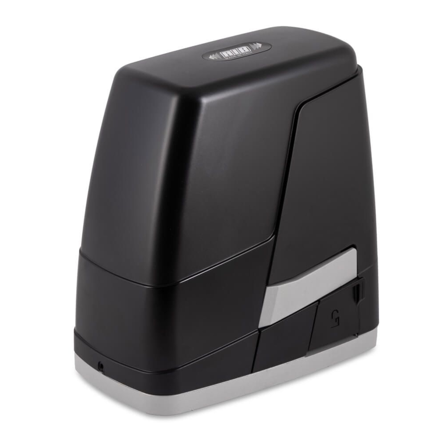
RIB K400 Manual
Hide thumbs
Also See for K400:
- Manual (68 pages) ,
- Simplified instructions (2 pages) ,
- Manual (21 pages)
Table of Contents
Advertisement
K400
Operatore
Alimentazione
Operateur
Alimentation
Operator
Torantrieb
Stromspannung
Operador
Alimentacion
230V 50/60Hz
K400
120V 60Hz
ITALIANO pag. 05 / FRANÇAIS page 16 / ENGLISH page 27 / DEUTSCH Seite 38 / ESPAÑOL pág. 49
Con quadro
Peso max cancello
Avec coffret
Poids maxi portail
With control board
Max gate weight
Mit Steuerung
Max Torgewicht
Con panel
Peso máx verja
electronico
K 24V-CRX
400 kg / 881 lbs
Spinta max
Coppia max
Poussée maxi
Couple maxi
Max Thrust
Max torque
Max Schubkraft
Max. Drehmoment
Max Empuje
Coppia max
434 N
14,7 Nm
Finecorsa
Codice
Fins de course
Code
Limit switch
Code
Endschalter
Code
Final de carrera
Codigo
elettromeccanici
électromagnétiques
electromechanical
AA40900
elektromechanisch
electromecánicas
magnetici
magnétiques
magnetic
AA40905
magnetisch
magnéticas
elettromeccanici
électromagnétiques
electromechanical
AA40901
elektromechanisch
electromecánicas
magnetici
magnétiques
magnetic
AA40906
magnetisch
magnéticas
Advertisement
Table of Contents

Summary of Contents for RIB K400
- Page 1 K400 Con quadro Operatore Alimentazione Peso max cancello Spinta max Coppia max Finecorsa Codice Avec coffret Operateur Alimentation Poids maxi portail Poussée maxi Couple maxi Fins de course Code With control board Operator Power Supply Max gate weight Max Thrust...
- Page 2 SYSTEM LAY-OUT 1 - K400 operating device 2 - External photocells 3 - Rack of Module 4 4 - Key selector 5 - Radio antenna 6 - Blinker 7 - Limit switch plate (cams) 8 - Mechanical strip 9 - Mechanical strip...
- Page 3 INSTALLATION K400 CHECKING BEFORE THE INSTALLATION !! THE GATE SHALL MOVE FRICTIONLESS !! N.B.: Gate features must be uniformed with the standards and laws in force. The door/ gate can be automated only if it is in a good condition and its conditions comply with the EN 12604 norm.
- Page 4 Insert the two 4MA self-locking nuts which are needed to fix the cover of the K400 operator before securing the operator to its base plate using the nuts and flat washers 8MA 8x26 provided (see Pict. 5).
-
Page 5: Electric Connections
MAINTENANCE REMOVE THE TRANSPARENT COVER FROM THE TOP OF THE To be carried out exclusively by skilled persons after the power supply to the motor ELECTRONIC BOARD BY UNSCREWING ITS 3 SCREWS. has been interrupted. Periodically, when the gate is standstill, clean and keep the guide free from stones and dirt. ELECTRIC CONNECTIONS K 24V-CRX cod. - Page 6 DIP 13 ON - photocells enabled only when closing ON - function dedicated to gear motor K800 OFF - photocells always enabled OFF - function dedicated to gear motor K400 DIP 5 DIP 14 ON - heater enabled ON - enable SUN/MOON radio system...
- Page 7 RESERVED > CONNECTOR RESERVED TO FACTORY CONTROLS. GATE AT ABOUT 20 CM FROM THE CLOSING LIMIT-SWITCH. 2 - Set DIP 2 to ON mode = > led DL1 starts flashing. RUN > TRIMMER FOR MOTOR SPEED ADJUSTMENT. 3 - Press the PROG button. The gate will begin a series of movements. DO NOT PASS IN With this trimmer it is possible to adjust the motor speed (set by default at half the speed).
- Page 8 RADIO CODE MEMORY FULL SIGNAL ENABLING THE CLOCK FUNCTION The signal will only be given when the gate is at a standstill. By connecting a switch and/or a daily/weekly clock to the “COM-B.I.O.” terminals, you can 1 - First, set DIP 1 to ON and then DIP 2 to ON. open the gate (and keep it open) until the switch or clock remain enabled.
- Page 9 8 OFF => immediate gate closure after transit on photocells disabled. seconds). Note 1: during this mode, if the edges (or photocells) experience a fault, they will continue to EDGE (COM-EDGE) work, interrupting the command in progress. With the edge enabled, the buzzer emits 2 tones. Note 2: the stop button is not considered a safety to be bypassed in this mode, therefore if If the edge intervenes while the gate is opening, it will cause the gate to to stop for 2 it is pressed or broken, it does not allow any command.
- Page 10 TABLE SUMMARISING ALARMS AND VISUAL AND SOUND SIGNALS SIGNALS DURING PROGRAMMING SEQUENCE EVENT BUZZER STATUS FLASHER STATUS PROGRAMMING LED DL1 STATUS DIP 1 ON (HOLD MODE) FLASHES ON-OFF 250 MS OR FAILURE OF A SAFETY DEVICE (ON STEADY MODE) DIP 2 ON (FULL STROKE PROGRAMMING) FLASHES ON-OFF 500 MS DIP 2>1 ON (PEDESTRIAN STROKE FLASHES ON-OFF 500 MS...
- Page 11 TECHNICAL SPECIFICATIONS TROUBLESHOOTING - Temperature range -10 ÷ +55°C After making all the connections, carefully following the diagram and having placed the gate - Humidity < 95% without condensation in intermediate position, check the correct lighting of led DL4, DL7, DL8 DL9, DL12, DL13 - Power supply 230V~ ±10% (120V 60Hz on request) and DL14.
- Page 12 ACG6224 SPARK BATTERY SPARK BLINKER WITH IN-BUILT INTERMITTENT CARD code ACG7061 LATERAL SUPPORT code ACG7042 1,2Ah 12V cod. ACG9511 SPARK ANTENNA 433 code ACG5452 In case of power failure, with two 1,2Ah batteries the K400 can run for 25 cycles.
- Page 13 ROND. PIANA 8.5X26X2.5 zincata CME2154 INGR. ACCIAIO K800/K1400/K2200 CTC1404 PARAOLIO 25 40 7 ROLF DST8X45 GRANO M8X45 UNI 5927 CON.BRUNI CME2178 BOCCOLA X LEVA SBLOCCO K400 24 CTC1406 PARAOLIO 10 26 7 DTB55X40 VITE TCEI 5,5X38 AUT.ZINC.C15 CME2179 PERNO SBLOCCO K400 24V CTC1441...
- Page 14 ROND. PIANA 8.5X26X2.5 zincata CME2154 INGR. ACCIAIO K800/K1400/K2200 CTC1406 PARAOLIO 10 26 7 DST8X45 GRANO M8X45 UNI 5927 CON.BRUNI CME2178 BOCCOLA X LEVA SBLOCCO K400 24 CTC1441 MOLLA GRUPPO SBLOCCO K4 DTB55X16 VITE TCEI 5,5X16 AUTOF. ZINC. CME2179 PERNO SBLOCCO K400 24V CTC1442...


Need help?
Do you have a question about the K400 and is the answer not in the manual?
Questions and answers