Table of Contents
Advertisement
Available languages
Available languages
Quick Links
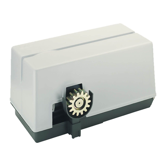
SUPER 3600
Operatore
Operateur
Operator
Torantrieb
Operador
SUPER 3600
SUPER 3600 ICE
Die korrekte Bedienung des Bedieners ist nur gewährleistet, wenn er von einem RIB-Bedienpanel verwaltet wird
El funcionamiento correcto del operador solo está garantizado si está gestionado por un panel de control RIB
ITALIANO pag. 05 / FRANÇAIS pag. 17 / ENGLISH page 29/ DEUTSCH pag. 41 / ESPAÑOL pag. 53
Alimentazione
Peso max cancello
Alimentation
Poids maxi portail
Power Supply
Max gate weight
Stromspannung
Max Torgewicht
Alimentacion
Peso máx verja
230V 50/60 Hz
3600 kg
Il corretto funzionamento dell'operatore è garantito solo se viene gestito da un quadro di comando RIB
Le bon fonctionnement de l'opérateur n'est garanti que s'il est géré par un panneau de contrôle RIB
The correct operation of the operator is guaranteed only if it is managed by a RIB control panel
con / avec / with / mit
Spinta max
Poussée maxi
Couple maxi
Max Thrust
Max Schubkraft
Max. Drehmoment
Max Empuje
4700/4150 N
200/175 Nm
1
L1/R2-CRX
Disegni tecnici per progetti
Dessins techniques pour les projets
Technical drawings for projects
Technische Zeichnungen für Projekte
Dibujos técnicos para proyectos.
Vedere pagina 15
Voir page 27
See page 39
Siehe Seite 51
Ver página 63
Coppia max
Codice
Code
Max torque
Code
Code
Coppia max
Codigo
AA31020
AA31024
Advertisement
Table of Contents

Subscribe to Our Youtube Channel
Related Manuals for RIB L1/R2-CRX


Summary of Contents for RIB L1/R2-CRX
- Page 1 Le bon fonctionnement de l’opérateur n’est garanti que s’il est géré par un panneau de contrôle RIB The correct operation of the operator is guaranteed only if it is managed by a RIB control panel Die korrekte Bedienung des Bedieners ist nur gewährleistet, wenn er von einem RIB-Bedienpanel verwaltet wird El funcionamiento correcto del operador solo está...
- Page 2 2° - En ce qui concerne la section et le type des câbles, RIB conseille d’utiliser un câble de 2° - Per la sezione ed il tipo dei cavi la RIB consiglia di utilizzare un cavo di tipo H05RN-F type H05RN-F ayant une section minumum de 1,5 mm 2 et de toute façon, s’en tenir à...
-
Page 3: Installation
(for example by installing inside a locked board). anerkanntes Konformitätszeichen besitzt. Solch ein Geraet muss vor Vandalismus 2° - For the section and the type of the cables RIB advices to use a cable of H05RN-F type geschuetzt werden (z.B.mit einen Schluesselkatsten in einem Panzergehaeuse). - Page 4 L’eliminazione dei materiali va fatta rispettando le norme vigenti. Non gettate il 2° - Para la sección y el tipo de los cables, RIB aconseja utilizar cables de tipo H05RN-F con vostro apparecchio scartato, le pile o le batterie usate nei rifiuti domestici. Avete la sección mínima de 1,5 mm 2 e igualmente atenerse a la norma IEC 364 y a las normas...
- Page 5 LAYOUT IMPIANTO A - Operatore SUPER 3600 B - Fotocellule esterne C - Cremagliera Modulo 6 D - Selettore a chiave E - Antenna radio F - Lampeggiatore H - Colonnina portafotocellula I - Fotocellula per protezione interna L - Costa meccanica M - Costa meccanica o elettrica con trasmettitore RED CARATTERISTICHE TECNICHE SUPER 3600...
- Page 6 INSTALLAZIONE SUPER 3600 CONTROLLO PRE-INSTALLAZIONE - IL CANCELLO DEVE MUOVERSI SENZA ATTRITI - N.B. È obbligatorio uniformare le caratteristiche del cancello alle norme e leggi vigenti. La porta può essere automatizzata solo se in buono stato e se rispondente alla norma EN 12604.
-
Page 7: Manutenzione
FISSAGGIO MOTORE E CREMAGLIERA La cremagliera va fissata a una certa altezza rispetto alla piastra di fissaggio del motore. Questa altezza può essere variata grazie a delle asole presenti sulla cremagliera. La registrazione in altezza viene fatta affinché il cancello durante il movimento, non si appoggi sull’ingranaggio di trazione del riduttore (Fig. -
Page 8: Collegamenti Elettrici
COLLEGAMENTI ELETTRICI L1 cod. AC08082 Manuali online interattivi Manuels interactifs en ligne Interactive online manuals Interaktive Online-Handbücher Manuales interactivos en línea. - Page 9 Connettore per modulo radio ACG8069 COM A+ Comune dei contatti / Positivo 24 Vdc RADIO Connettore per radio ricevitore rib ad innesto con alimentazione a 24 Vdc. A+ COM Positivo alimentazione accessori a 24 Vdc / Comune dei contatti Antenna radio 433 MHz Negativo alimentazione accessori a 24 Vdc PROG.
- Page 10 B - SETTAGGI DL15 Comando PROG e RADIO su molex (verde) B.I.O Comando orologio (verde) PED. Comando apertura pedonale (verde) DIP 1 (ON) - CONTROLLO PER MANUTENZIONE (PAG. 13) START Comando impulso singolo (verde) DIP 2 (ON) - PROGRAMMAZIONE TEMPI (PUNTO C) CLOSE Comando Chiude (verde) DIP 2-1 PROGRAMMAZIONE TEMPI APERTURA PEDONALE (PUNTO D)
- Page 11 2 - Entro questi 10 secondi premere il pulsante del telecomando (normalmente il canale A). Tramite App RIB GATE è possibile configurare il funzionamento di questo relé a Se il telecomando viene correttamente memorizzato il led DL12 si accende verde ed un piacere.
-
Page 12: Funzionamento Accessori Di Sicurezza
Durante l’apertura, la pausa o la chiusura pedonale, è possibile comandare l’apertura da PED. funzioneranno solo con comando mantenuto. qualsiasi comando collegato sulla scheda B2 24V. La segnalazione dell’attivazione di questo funzionamento è data dal led DL1 che lampeggia. Tramite DIP 6 è possibile scegliere la modalità di funzionamento del pulsante di comando Il comando radio e la chiusura automatica vengono esclusi in quanto il loro funzionamento pedonale. -
Page 13: Risoluzione Problemi
RISOLUZIONE PROBLEMI generata internamente (tensione sicura) alla scheda ed è disposta in modo da garantire il rispetto di isolamento doppio o rinforzato rispetto alle parti a tensione pericolosa. - Eventuali circuiti esterni collegati alle uscite del quadro elettronico, devono essere eseguiti Dopo aver effettuato tutti i collegamenti seguendo attentamente lo schema ed aver per garantire l’isolamento doppio o rinforzato rispetto alle parti a tensione pericolosa. - Page 14 DIFETTO SOLUZIONE Sulla scheda esistono dei fusibili ripristinabili che intervengono in caso di corto circuito interrompendo l'uscita a loro assegnata. A fronte di una ricerca guasti si consiglia di scollegare tutti i connettori estraibili e di inserirli uno a volta in modo da identificare più facilmente la causa del guasto. Dopo aver effettuato i vari collegamenti e aver dato tensione, tutti i led sono spenti.
- Page 15 APP8054 Scheda APP+ APP8050 Scheda APP per gestire la centrale di comando per gestire la centrale di comando tramite Bluetooth tramite Bluetooth APP8064 Modulo Wi-Fi per Scheda APP8066 Modulo RJ45 per Scheda APP+ APP+ per gestire la centrale tramite rete per gestire la centrale tramite rete Wi-Fi locale (WLAN) dati locale (LAN)
- Page 16 RED permette la realizzazione di un impianto con coste fissate anche sull’anta in movimento senza l’adozione di sistemi raccogli cavo. È conforme alla norma EN13849-1:2007 e congiuntamente ad un quadro elettronico RIB è un dispositivo di protezione di Classe 2.
-
Page 17: Caractéristiques Techniques
SCHÉMA DÉTAILLÉ DE L’INSTALLATION A - Operateur SUPER 3600 B - Photocellules p/protec. externe C - Cremaillere m6 D - Selecteur E - Antenne radio F - Signal electrique H - Poteau zingué p/cellule ne I - Photocellules p/protection interne L - Barre palpeuse mécanique fixé... - Page 18 INSTALLATION SUPER 3600 CONTRÔLE PRÉ-INSTALLATION !! LE PORTAIL DOIT SE DÉPLACER SANS FROTTER !! N.B.: Il est impératif d’uniformiser les caractéristiques du portail avec les normes et les lois en vigueur. La porte peut être automatisée seulement si elle est en bon état et qu’elle est conforme à...
-
Page 19: Entretien
INSTALLATION DU MOTOR E DE LA CREMAILLERE La crémaillère doit être fixée à une certaine hauteur par rapport à la base du moteur. Cette hauteur peut être modifiée grâce à des boutonnières qui sont présentes sur la crémaillère. Le réglage en hauteur est effectué afin que le portail ne s’appuie pas sur l’engrenage de traction du réducteur (Fig. -
Page 20: Branchements Électriques
BRANCHEMENTS ÉLECTRIQUES L1 code AC08082 Manuali online interattivi Manuels interactifs en ligne Interactive online manuals Interaktive Online-Handbücher Manuales interactivos en línea. - Page 21 A - BRANCHEMENTS IL EST OBLIGATOIRE DE PROG INSTAURER LA FICHE AVEC DIP 13 EN POSITION “ON”. POWER 230 VAC MOTOR CAPACITOR RS485 terminaison de J11 L1 - N Alimentation 230 Vca 50/60 Hz (120 V 60 Hz sur demande) Clignotant (max 40 W) APP+ Connecteur de carte APP+...
- Page 22 B - RÉGLAGES DL13 L1 géré par APP (bleu) DL14 Encodeur active (rosso) DIP 1 CONTRÔLE D’ENTRETIEN (PAGE 25) (ON) DL15 Commande PROG et RADIO sur molex (vert) DIP 2 PROGRAMMATION DE LA DURÉE (ON) (POINT C) B.I.O. Commande de horloge (vert) DIP 2-1 PROGRAMMATION DES LAPS DE TEMPS D’OUVERTURE POUR PIÉTONS (DIP PED.
- Page 23 R-AUX fonctionne normalement comme une lumière de courtoisie pendant 3 minutes. la programmation des codes sont automatiquement renouvelées avec la LED DL12 qui Grâce à l’application RIB GATE, il est possible de configurer le fonctionnement de ce clignote en rouge pour pouvoir mémoriser la télécommande suivante.
- Page 24 TÉLÉCOMMANDE BOUTON D’ARRÊT (COM A+/STOP) - Fonction de sécurité PL”b” selon EN13849-1 SI DIP 6 sur ON => effectue une commande cyclique des commandes ouvre-arrête-ferme- Pendant le mouvement, le bouton d’arrêt effectue l’arrêt du portail. arrête-ouvre etc. Si le bouton STOP est enfoncé lorsque le portail est totalement ouvert (ou partiellement, au Si DIP 6 sur OFF =>...
- Page 25 - Courant disponible pour photocellules et accessoires 400 mA 24 Vcc SOLUTION DES PROBLEMES - Courant disponible sur connecteur radio 200 mA 24 Vcc Après avoir effectué tous les raccordements en suivant attentivement le schéma et avoir positionné le portail en position intermédiaire, vérifier l’allumage correct des leds rouges CARACTÉRISTIQUES TECHNIQUES RADIO (seulement modèles CRX) DL6, DL7, DL8, DL9 et DL10.
- Page 26 TABLEAU RÉCAPITULATIF ALARMES VISUELLES ET SONORES SIGNALISATIONS EN COURS DE PROGRAMMATION ÉVÉNEMENT ÉTAT BUZZER ÉTAT CLIGNOTEUR ÉTAT LED DL1 Dip 1 ON (mode homme mort) Éteint Éteint Clignote 250 ms on-off Ou panne d'une sécurité Dip 2 ON (programmation course totale) Éteint Éteint Clignote 500 ms on-off...
- Page 27 MODULE RADIO 433MHz EMETTEUR RADIO SUN cod. ACG8069 SUN 2CH cod. ACG6052 SUN 4CH cod. ACG6054 SUN CLONE 2CH cod. ACG6056 SUN CLONE 4CH cod. ACG6058 SUN-PRO 2CH cod. ACG6210 SUN-PRO 4CH cod. ACG6214 SUN-PROX 2CH cod. ACG6220 SUN-PROX 4CH cod.
- Page 28 RED permet la réalisation d’une installation avec barres palpeuses fixées également sur le battant en mouvement sans l’adoption de systèmes d’assemblage de câbles. Il est conforme à la norme EN13849-1:2007 et associé à un tableau électronique RIB, il est un dispositif de protection de Classe 2.
-
Page 29: System Layout
SYSTEM LAY-OUT A - SUPER 3600 operator B - Photoelectric cells (external) C - Rack M6 D - Key selector E - Tuned aerial F - Flashing lamp H - Galvanized column for P.E. cells I - Photo electric cells (internal) L - Safety strip fixed to column M - Mecanichal or electrical safety strip with RED transmitter TECHNICAL DATA... -
Page 30: Emergency Release
INSTALLATION SUPER 3600 CHECKING BEFORE THE INSTALLATION !! THE GATE SHALL MOVE FRICTIONLESS !! 2” N.B.: Gate features must be uniformed with the standards and laws in force. The door/ gate can be automated only if it is in a good condition and its conditions comply with the EN 12604 norm. -
Page 31: Limit Switch Adjustment
MOTOR AND RACK INSTALLATION The rack must be fixed at a certain height with respect to the motor base. This height can be varied thanks to the slots on the rack. The height needs to be adjusted so that the gate does not rest on the reduction unit traction gear (Fig. - Page 32 ELECTRIC CONNECTIONS L1 code AC08082 Manuali online interattivi Manuels interactifs en ligne Interactive online manuals Interaktive Online-Handbücher Manuales interactivos en línea.
- Page 33 Connector for radio module ACG8069 COM A+ Common contacts / Positive 24 Vdc RADIO Connector for radio receiver RIB, 24 Vdc supply A+ COM + 24Vdc accessories power supply / Common contacts 433 MHz Radio antenna - 24Vdc accessories power supply PROG.
- Page 34 POINT B - SETTINGS OPEN OPEN command (NO) (green) DIP 1 MAINTENANCE CHECK (See Page 36) PROBE DIP 2 PROGRAMMING (See Point C) IS NOT AVAILABLE DIP 2-1 PROGRAMMING OF PEDESTRIAN OPENING (See Point D) DIP 1-2 SAVE/DELETE RADIO CODES FOR COMPLETE OPENING (DIP 1 ON followed POINT C - TIMES PROGRAMMING by DIP 2 ON) (POINT E) DIP 1-3 SAVE/DELETE RADIO CODES FOR PEDESTRIAN OPENING (DIP 1 ON...
- Page 35 4 - Re-Set DIP 1, 2, 3 to OFF. ALL RADIO CODES FOR TOTAL OPENING CANCELLATION PROCEDURE 5 - End of procedure. Cancellations can only be performed when gate is stationary. RADIO CODES MEMORY FULL INDICATOR (FOR R-AUX RELAY) 1 - Set DIP 1 to ON and then DIP 2 to ON. 2 - LED DL12 flashes red for 10 seconds.
- Page 36 Connect the photocell transmitter to A+ TEST/A- and set DIP 7 to ON. When the gate is stationary or opened, it is permanently on. The monitoring consists of a functional test of the photocell run before every movement. During closing, it flashes quickly The gate movement is therefore permitted only if the photocells have passed the functional N.B.: Max 3 W.
- Page 37 DL9 or DL10 Faulty safety edge (In case the edge is not connected, carry out jumper between COM A+ and EDGE 1/EDGE 2) LED DL13 (BLUE) Some functions are enabled via smartphone, so via smartphone check the card functions as the dips/trimmers status may not be true. On the board there are resettable fuses which intervene in the event of a short circuit, interrupting the output assigned to them.
- Page 38 FAULT SOLUTION After having carried out the various connections and having supplied voltage, all the LEDS On the board there are resettable fuses which intervene in the event of a short circuit, are switched off. interrupting the output assigned to them. In the event of troubleshooting, it is advisable to disconnect all the removable connectors and insert them one at a time in order to more easily identify the cause of the fault.
- Page 39 ACCESSORIES - For the connections and the technical data of the optional equipments follow the relevant handbooks. APP8050 APP card APP8054 APP+ card to manage the control panel using to manage the control panel using Bluetooth 4.2 transmission Bluetooth 4.2 transmission APP8064 Wi-Fi module for APP+ APP8066 RJ45 module for APP+ card...
- Page 40 RED allows to make a system made with edges fixed to the moving shutter without having to use cable sleeving systems. It complies with EN13849-1:2007 Standard, if installed with an RIB Electronic Board it is a Class-2 Device. code ACG6202...
-
Page 41: Technische Eigenschaften
ANLAGEN LAY-OUT A - Torantrieb SUPER 3600 B - Photozelle Toraussenseitig C - Zahnstange M6 D - Schlusselschalter E - Antenne F - Blinkleuchte H - Verzinkte Metallsäule als Photozellentrager I - Photozelle - Torinnenseitig L - Sicherheitskontaktleiste auf dem Schiebetor M - Mechanische oder elektrische Sicherheitsanlage mit Handsender RED TECHNISCHE EIGENSCHAFTEN SUPER 3600... - Page 42 INSTALLATION SUPER 3600 VOR DER MONTAGE AUSZUFÜHRENDE ÜBERPRÜFUNGEN !! DAS TOR MUSS REIBUNGSFREI LAUFEN !! ANMERKUNG: Es ist erforderlich, die Charakteristiken des Tors an die geltenden Normen und Gesetze anzupassen. Das Tor kann nur automatisch Angeschlossen werden, wenn es in einem einwandfreien Zustand ist und der EN12604 entspricht.
-
Page 43: Wartung
MOTORBEFESTIGUNG UND ZAHNSTANGE (Abb. 5-6) Die Zahnstange muß in bestimmten Abstand von der Verankerungsplatte befestigt werden. Die Zahnstange darf nicht angeschweißt, sondern nur mit Hilfe von Gewindeschrauben an dem Gittertor befestigt werden. Die Höheneinstellung soll verhindern, daß das Gittertor auf dem Antriebszahnrad des Antriebes aufliegt. - Page 44 ELEKTROANSCHLÖÜSSE L1 Kode AC08082 Manuali online interattivi Manuels interactifs en ligne Interactive online manuals Interaktive Online-Handbücher Manuales interactivos en línea.
- Page 45 Verbinder für Radio-Modul ACG8069 COM A+ Gemeinsame erdungskontakte / Positive 24 Vdc J16 RADIO Verbinder für Radioempfänger RIB Steckverbindung mit Speisung zu A+ COM Positive Ladung für die Speisung der Zubehöre zu 24Vdc 24Vdc Negative Ladung für die Speisung der Zubehöre zu 24Vdc...
- Page 46 B - EINSTELLUNGEN DL15 PROG- und RADIO-Befehle (am MOLEX-Anschluss) (Grün) B.I.O Uhr Befehl (NO) (Grün) DIP 1 WARTUNGSÜBERPRÜFUNG (SIEHE SEITE 49) PED. Fußgänger Öffnungsbefehl (NO) (Grün) DIP 2 ZEITPROGRAMMIERUNG (ON) (PUNKT C) START Einzelimpulsbefehl (NO) (Grün) DIP 2 - 1 ZEITPROGRAMMIERUNG ÖFFNUNG FUSSGÄNGER (DIP 2 ON GEFOLGT VON CLOSE Befehl Schließen (NO) (Grün) DIP 1 ON) (PUNKT D)
- Page 47 R-AUX arbeitet normalerweise 3 Minuten lang als Zusatzbeleuchtung. von 10 Sekunden drücken. Wenn die Fernsteuerung korrekt programmiert worden ist, Über die RIB GATE-App kann der Betrieb dieses Relais wie gewünscht konfiguriert die LED DL12 blinkt Grün und des Summers Fragen 2 Töne. Die 10 Sekunden für die werden.
- Page 48 Während der Öffnung der Pause oder der Schließung der Fußgänger-Öffnung, kann die Wenn eine der Kontaktleisten ist defekt oder diese arbeit länger als 5 Sekunden, oder wenn Öffnung mit jedem mit dem Steckverbinder B2 24V verbundenem Befehl geöffnet werden. eine der Fotozellen defekt ist oder für mehr als 60 Sekunden arbeit, die OPEN, CLOSE, START Über DIP 6 kann man die Funktionsweise der Taste zur Fußgänger-Öffnung wählen.
- Page 49 - Alle Eingänge müssen als (wie) saubere Kontakte benutzt werden, da die Speisung im LÖSUNG VON PROBLEMEN Inneren der Schaltkarte (sichere Spannung) erzeugt wird und so vorgesehen ist, dass eine Beachtung der doppelten oder verstärkten Isolierung gegenüber den Teilen mit gefährlicher Nachdem alle Verbindungen sorgfältig dem Schema folgend ausgeführt wurden und das Tor Spannung garantiert werden kann.
- Page 50 ÜBERSICHTSTABELLE DER VISUELLEN UND AKUSTISCHEN ALARMEN SIGNALISIERUNGEN WÄHREND DER PROGRAMMIERPHASE EREIGNIS STATUS BUZZER STATUS BLINKLEUCHTE STATUS LED DL 1 DIP 1 ON (“befehl gedrückt gehalten”-modus) Abgeschaltet Abgeschaltet Blinkt 250 ms ein-aus oder defekt einer sicherheitsvorrichtung DIP 2 ON (laufprogrammierung ganz) Abgeschaltet Abgeschaltet Blinkt 500 ms ein-aus...
- Page 51 FERNSENDER SUN RADIO-MODUL 433MHz SUN 2CH Kode ACG6052 SUN 4CH Kode ACG6054 Kode ACG8069 SUN CLONE 2CH Kode ACG6056 SUN CLONE 4CH Kode ACG6058 SUN-PRO 2CH Kode ACG6210 SUN-PRO 4CH Kode ACG6214 SUN-PROX 2CH Kode ACG6220 SUN-PROX 4CH Kode ACG6224 APP8050 APP-Karte APP8054 APP+-Karte um das Steuerung mit Bluetooth...
- Page 52 RED erlaubt die Realisierung einer Anlage mit Kontaktleisten, die auch auf dem sich bewegenden Tor angebracht sein können, ohne dass man Kabelsammelsysteme benötigt. Entspricht der Norm EN13849-1:2007 und in Verbindung mit einer RIB - Schalttafel stellt es eine Schutzvorrichtung der Klasse 2 dar. Kode ACG6202...
-
Page 53: Características Técnicas
DISPOSICIÒN DE LA INSTALACIÒN A - Operador SUPER 3600 B - Fotocélulas externas C - Cremallera Módulo 4 D - Interruptor de llave E - Antena de radio F - Intermitente H - Columnas para las fotocélulas I - Fotocélulas internas L - Nervadura mecánica M - Nervadura mecànica o elèctrica con transmisor RED CARACTERÍSTICAS TÉCNICAS... - Page 54 INSTALACIÓN SUPER 3600 CONTROL PRE-INSTALACIÓN ¡¡LA VERJA TIENE QUE MOVERSE SIN ROCES!! IMPORTANTE: Es obligatorio uniformar las características de la verja a las normas y leyes en vigor. La puerta puede ser automatizada sólo si se encuentra en buen estado y responde a la norma EN 12604. - La puerta no tiene que tener puertas peatonales.
-
Page 55: Mantenimiento
ANCLAJE MOTOR Y CREMALLERA (Fig. 5-6) La cremallera se tiene que anclar a una determinada altura respecto al soporte del motor. Dicha altura se puede variar gracias a unos ojales presentes en la cremallera. El ajuste de la altura se efectúa para que la verja durante el movimiento no se apoye sobre el engranaje de tracción del K (Fig. - Page 56 CONEXIONES ELÉCTRICAS L1 cód. AC08082 Manuali online interattivi Manuels interactifs en ligne Interactive online manuals Interaktive Online-Handbücher Manuales interactivos en línea.
- Page 57 Conector para módulo radio ACG8069 COM A+ Común de los contactos / Positivo 24 Vdc RADIO Conector para radio receptor RIB con alimentación de 24Vdc A+ COM Positivo 24 Vdc / Común de los contactos Antenna radio 433 MHz Negativo 24Vdc para alimentación accesorios PROG.
- Page 58 B - AJUSTES B.I.O. Mando reloj (NA) (verde) PED. Mando de apertura peatonal (NA) (verde) DIP 1 CONTROL DE MANTENIMIENTO (ON) (PÁGINA 61) START Mando de impulso unico (NA) (verde) DIP 2 PROGRAMACIÓN DE LOS TIEMPOS (ON) (PUNTO C) CLOSE Mando de cierre (NA) (verde) DIP 2-1 PROGRAMACIÓN DE LOS TIEMPOS DE APERTURA PEATONAL (DIP 2 ON OPEN Mando de apertura (NA)
- Page 59 2 - Dentro de los 10 segundos presione la tecla del mando a distancia (normalmente el canal * La gestión del control remoto solo se puede activar con la aplicación RIB GATE. A). Si el mando a distancia se memoriza correctamente, el led DL12 emite un parpadeo R-AUX normalmente funciona como una luz de cortesía durante 3 minutos.
- Page 60 Si DIP 6 en ON => Ejecute un mando cíclico de órdenes abre-stop-cierra-stop-abre etc. para volverla a cerrar. Si DIP 6 en OFF => Ejecute la apertura con cancela cerrada. Si se acciona durante el En el ciclo sucesivo, la función de cierre automático es reactivada (si habilitada mediante movimento de apertura, no tiene efecto.
-
Page 61: Resolución De Problemas
CARACTERÍSTICAS TÉCNICAS DE RADIO (modelo L1-CRX) RESOLUCIÓN DE PROBLEMAS - Frecuencia de recepción 433,92MHz Después de haber efectuado todas las conexiones siguiendo atentamente el esquema y - Impedancia 52 ohm haber posicionado el portón en posición intermedia, verifique el correcto encendido de los - Sensibilidad >1 µV led rojos DL6, DL7, DL8, DL9 y DL10. - Page 62 TABLA SINÓPTICA DE LAS ALARMAS VISUALES Y ACÚSTICAS SEÑALIZACIONES EN FASE DE PROGRAMACIÓN EVENTO ESTADO DE BUZZER ESTADO DE L'INTERMITENTE ESTADO LED DL1 Dip 1 ON (modo persona presente) Apagado Apagado Parpadea 250 ms on-off O bien avería de un seguro (modo funciona siempre) Dip 2 ON (programación carrera total) Apagado Apagado...
- Page 63 MÓDULO RADIO 433MHz TELEMANDO SUN SUN 2CH cód. ACG6052 SUN 4CH cód. ACG6054 cod. ACG8069 SUN CLONE 2CH cód. ACG6056 SUN CLONE 4CH cód. ACG6058 SUN-PRO 2CH cód. ACG6210 SUN-PRO 4CH cód. ACG6214 SUN-PROX 2CH cód. ACG6220 SUN-PROX 4CH cód. ACG6224 APP8054 Tarjeta APP+ APP8050 Tarjeta APP para administrar la unidad de...
- Page 64 RED permite realizar una instalación con costas colocadas incluso sobre la hoja en movimiento sin la adopción de sistemas recoge cables. Conforme a la norma EN13849-1:2007. Unido a un cuadro electrónico RIB es un dispositivo de protección de Clase 2.
- Page 65 COLLEGAMENTI FOTOCELLULE - CONNEXIONS PHOTOCELLULE - PHOTOCELLS CONNECTIONS FOTOZELLEN VERBINDUNGEN - CONEXIONES FOTOCÉLULAS 4 fotocellule FIT SLIM / FIT SYNCRO con autotest e sincronizzatore del segnale infrarosso 2 fotocellule FIT SLIM, FIT SYNCRO con autotest 4 photocellules FIT SLIM / FIT SYNCRO avec autotest et synchroniseur de signal infrarouge 2 photocellules FIT SLIM, FIT SYNCRO avec autotest 4 FIT SLIM / FIT SYNCRO photocells with self-test and infrared signal synchronizer 2 photocells FIT SLIM, FIT SYNCRO with self-test...
- Page 66 COLLEGAMENTI FOTOCELLULE - CONNEXIONS PHOTOCELLULE - PHOTOCELLS CONNECTIONS FOTOZELLEN VERBINDUNGEN - CONEXIONES FOTOCÉLULAS 4 fotocellule NOVA sincronizzate con autotest 4 photocellules NOVA synchronisées avec autotest 4 NOVA photocells synchronized with self-test 4 NOVA Photozellen synchronisiert mit Selbstkontrolle 4 fotocélulas NOVA sincronizadas con autotest PHOT1 PHOT2 A+ TEST COM A+...
- Page 67 SUPER 3600 BA03001 CVA1023 CTC1405 CCU6307 CME1063 CTC1044 CME8087 CME1034 CTC1409 CZM6008 CME5105 CTC1168 CTC1084 CME1998 CTC1127 CTC1101 BA00159 (230 V-50/60 Hz) CPL1119 CCU6207 BA03615 CME1079 CVA1361 CTC1126 CVA1391 CPL1020 Codice Denominazione Particolare CCU6307 Cuscinetto 6307 35x80x21 CTC1084 Anello di tenuta OR106 ACG1080 Chiave per serratura carter CEL1433...
- Page 68 SUPER 3600 Modèle d'appareil : Objet de la déclaration : Apparatus model : Object of the declaration : L1/R2-CRX Vorrichtung Modell : Gegenstand der Erklärung : Modelo de aparato : Objeto de la declaración : I seguenti requisiti essenziali della Direttiva Macchine (2006/42/ Directives Européennes, couvertes par de telles normes ou parties...
Need help?
Do you have a question about the L1/R2-CRX and is the answer not in the manual?
Questions and answers