
Subscribe to Our Youtube Channel
Related Manuals for HygroMatik Basic- DS


Summary of Contents for HygroMatik Basic- DS
- Page 1 Manual Controls Basic- DS Comfort- DS Comfort Plus- DS Steam Bath 45.0 °C °C Steam Bath 45.0 °C °C ÁDS.ENLÈ DS.EN READ AND SAVE THESE INSTRUCTIONS!
- Page 2 Current version of this manual can be found at: www.hygromatik.co.uk HygroMatik GmbH grants the legal user of this product [or device] the right to use the Work(s) solely within the scope of the legitimate operation of the product [or device]. No other right is granted under this licence.
-
Page 3: Table Of Contents
1. Introduction ............................6 1.1 Typographic Distinctions ........................6 1.2 Documentation ..........................6 1.3 Directions for Use ..........................7 2. Safety Notes ............................. 8 2.1 Overview ............................8 2.2 Guidelines for Safe Operation ......................8 2.3 Disposal after Dismantling ....................... 9 3. - Page 4 7.3.4.1 Collective Fault - Base Relay ..................... 59 7.3.4.2 Humidification: ..........................60 7.3.4.3 Signal Output ..........................60 8. Fault Messages (Comfort- DS / Comfort Plus- DS und Basic- DS) ..........61 9. To the Installer ..........................64 9.1 Temperature Sensor Installation ...................... 64 9.1.1 Temperature Sensor Connection ....................
- Page 5 14. Terminal Assignments on the Unit Connector Strip and Wiring Diagram Legend ....85 15. Wiring Diagram ..........................86 16. Ordering Information / Table of Options ..................94 17. Technical Specifications ....................... 97 Page 5...
-
Page 6: Introduction
Dear Customer, Thank you for choosing a HygroMatik steam humidifier. HygroMatik s team hu midifiers re present t he late st in h umidification technology. They will impr ess you with their safety, ease of use an d e conomical operation. -
Page 7: Directions For Use
1.3 Directions for Use The proven principle of heating water by the use of electric immersion heaters is exploited to generate steam. Warning: Only q ualified a nd au thorised personnel may o perate the unit. Persons transporting or working on the unit , must have read and understood the corresponding parts of the Operation and Maintenance Instruction a nd e specially the chap ter 2 . -
Page 8: Safety Notes
2. Safety Notes 2.1 Overview These safety notes a re required by law . The y p romote workplace safety and accident prevention. Warnings and Safety Symbols The safety symbols below identify sections containing warnings about hazards or potential d angers. Pleas e familiari ze yourself with thes e symbols. -
Page 9: Disposal After Dismantling
Warning: M ake sur e that n o ig nitable gas m ixture can g et in to the steam cylinder. Accident Prevention RegulationsComply with the accident preven- tion regulation Accident Prevention Regulation Electrical Systems and Equipment (VBG4/BGVA2) to prevent injury to yourself and others. Operation of the Unit Do not perform any work which compromises the safety of the unit. -
Page 10: Comfort- Ds / Comfort Plus- Ds
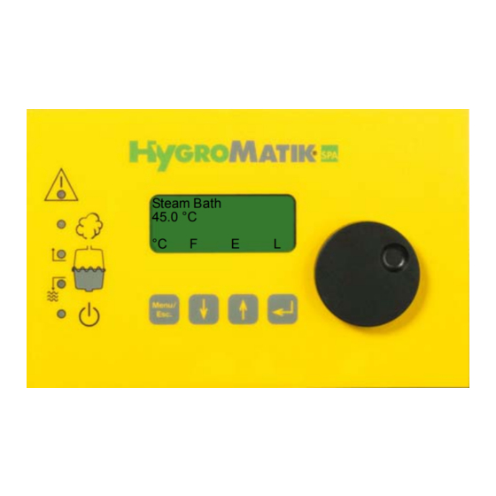
3. Comfort- DS / Comfort Plus- DS The display and operating panel enables local communication with the steam generator. 3.1 General V iew of DS-Contro l and Operating Panel DS-Control Display and Operating Panel The display is su pplied as a four-line, lig hted L C-display. O nce the humidifier is switched on, it shows: 1st Line: Operating mode of the steam bath steam generator and sta- tus of fan, essence delivery and light. -
Page 11: Communication With The Control
LED colors: yellow yellow yellow green A: Malfunction B: Steady LED = humidification; blinking LED = maximum water C: Filling D: Blow-Down E: Steady LED = ready; blinking LED = maintenance interval 3.2 Communication with the Control Local co mmunication with th e Comfort / Co mfort Plu s control (d ata input and output) is possible using the display and keypad. -
Page 12: Ds-Comfort And Ds-Comfort Plus Compared
3.3 DS-Comfort and DS-Comfort Plus Compared Comfort- DS Comfort Plus- DS Encoder Knob Unlike the DS-Comfort, the DS-Comfort Plus is equipped with an addi- tional encoder knob for easy use. Turning the knob left or right is equivalent to pressing the software keys “up arrow“... -
Page 13: User Mode - Communication With The Control (Comfort-Ds/ Comfort Plus-Ds)
4. User Mode - Communication with the Con- trol (Comfort-DS/ Comfort Plus-DS) After switchin g on the stea m hu midifier, th e use r is pla ced in user mode. This mode includes the indicators and controls needed to mo dify the following parameters: Temperature Set Value °C... -
Page 14: Steam Bath Exhaust Fan (D1)
Steam Bath 45 °C » Hold down until the temperature value 42°C appears 42 °C on the display. Menu Steam Bath » Press once. 42 °C Menu The new temperature set valu e is p rogrammed. After a few seco nds, the p rogram jum ps b ack to the st andard displ ay. -
Page 15: Light - Function
Delivery System Off By pressing the key once, the Essence Injector Parameter is set Steam Bath continuously to off. This is indicated in the display by an e and results 45 °C in no essence delivery into the steam bath. °C 4.1.4 Light - Function Light (on / off) - Page 16 Note: Lig ht contr ol, fa n contr ol an d essen ce injection control are optional a ccessories.HygroMatik steam bath systems ar e ava ilable either in 24V or 230V versions.
-
Page 17: Steam Bath Installation (Schematic Layout)
4.2.1 Steam Bath Installation (Schematic Layout) Location Designation Steam generator Essence peristaltic pump Essence reservoir Essence line to steam hose T-piece for essence feed into the steam hose Steam Steam manifold in steam bath bath supply fan Temperature sensor bath exhaust fan Cabin light Note: The illus tration below depict s a s chematic layout for a s team bath - it is not an installation instruction. -
Page 18: Steam Bath - Temperature Control
4.2.2 Steam Bath - Temperature Control With an y st eam bath, a temperature se nsor must be installed in th e cabin. The temperature sensor me asures the temperature in the steam bath and is connected to the steam generator. The DS- Comfort o r DS-Com fort Plus co ntrols the Hyg roMatik stea m generator according to the temperature reading. - Page 19 Steam is only produced as long as th e temperature in the steam bath remains b elow the “set tem perature valu e.” If the temperature in the steam ba th re mains a bove th e “se t temp erature valu e” fo r a lo ng period of time, resulting in this case in no v isible steam pr oduction, this could be due to: •...
-
Page 20: Diagramm Temperature Profile In Steam Bath
4.2.2.1 Diagramm Temperature Profile in Steam Bath Temperature Profile in Steam Bath Temperature 46,0 °C 45,0 °C 44,0 °C Time Steam Production Steam Bath Exhaust Steam Bath Sup- ply Fan Essence Delivery A: Duration / Essence Delivery B: Interval / Essence Delivery ein / on aus / off Page 20... -
Page 21: Operating Mode - Advanced Communication With The Control (Comfort-/Comfort Plus-Ds)
5.1 Introduction to the Comfort- DS / Comfort Plus- DS Control Control of yo ur HygroMatik steam humidifier is performed by so phisti- cated micr oprocessors. Th ese micro processors in telligently a nd self- adaptively select the most economical mode of operation for the steam humidifier appropriate to the existing water quality. - Page 22 LED colors: yellow yellow yellow green A: Malfunction B: LED steady = humidification; LED blinking = maximum water C: Filling D: Blow-Down E: LED steady = ready; LED blinking = maintenance interval The green LED blinks when the service interval has expired, and “Ser- vice”...
-
Page 23: Software Menu And Parameter Setting
5.2 Software Menu and Parameter Setting System Desired test Temperature Value System settings Power Parameters Page 23... - Page 24 Local co mmunication (da ta e ntry an d r eadout) is p ossible with the Comfort / Comfort Plus Control using the display and the keypad. The most important types of communication are: • Readout/Modification of steam bath operational values (in User Mode) •...
-
Page 25: Access To Operating Mode
5.2.1 Access to Operating Mode After switchin g on the stea m hu midifier, th e use r is pla ced in user mode. The display shows the following: Steam Bath Display 41,5 °C User Mode °C Function When the key is pressed, the software key “°C”... -
Page 26: Function Keys
5.2.2 Function Keys Keys are located below the display. Above each key, a context-based action (software key) is shown on the lowest line of the display (i.e. an “°C” key). The action is performed by press- ing the key. The sof tware keys in the d isplay u nit en able parameter modification. -
Page 27: Language Menu
5.3.1 Language Menu In this m enu, you can select the language in which you communicate with the humidifier. Sprache / Language German English French Spanish Japanese Italian Programming sequence to modify the language: press in Operating Mode, Sprache/Language Sprache/Language select the desired language with and confirm with English... -
Page 28: Control Parameters Submenu (Under Startup Menu)
5.3.2.1 Control Parameters Submenu (under S tartup Menu) Summary of Parameters: Para- Description Possible Settings Access Code meter Controls 1 Step (On/Off) MODBUS Mehrstufig internal PI-controller Steam ge neration 25-100% output limiter [%] Xp-PI-controller [0- 100 %] =100/E1 [Amplification] Tn-PI-controller [0- 255sec.] [Integration time] * Only when internal PI-controller is activated... - Page 29 Operation Mode » ress Parameters Output limit » press until Parameter U6 is displayed P1: 100% Operation Mode » press U6: internal PI controller Operation Mode » press to select “1-step” U6: 1-step Operation Mode » confirm with U6: 1-step Operation Mode »...
-
Page 30: System Test Submenu (Under Startup Menu)
5.3.2.2 System Test Submenu (under Startup Menu) This test ena bles checks of var ious humidifier functions (for example, during start-up). The following test routines can be executed: System Test Automatic System Test (includes all stand-alone tests) LED Test (stand-alone test) Pump/MV test (stand-alone test) Control Status Test (stand-alone test) To s elect the “Sys tem Test”... - Page 31 Sample Display Status Solenoid va lve out of order or no Test Valve / Pump water supply; also see Section: “Mal- Fault Filling functions and Messa ges”. Fault Fill- ing. Blow-down pum p ou t o f or der; also Test Valve / Pump see Section: “...
-
Page 32: Electronic Name Plate Menu
5.3.3 Electronic Name Plate Menu The display can show 6 different sets of unit data. Electronic Name Plate Cylinder number Nominal capacity [kg/h] Software version Model type Year of manufacture Serial number S10 Equipment designation » press in Operating Mode, press in Operating Mode, Sprache/Language... -
Page 33: Parameter Setting Menu
5.3.4 Parameter Setting Menu Parameters p artly de termine the h umidifier’s seq uence of o perations and processing of signals. These parameters can be modified as needed. For security r easons, access to so me parameters is pr otected by an entry code. -
Page 34: Parameters
6. Parameters 6.1 Summary Table of Parameters Para- Designation Possible Settings in Menu / Submenu Access Code meter Standby Blow-down 0 Min. - 999 Hours[ HHH : MM Parameter Setting/Blow- none Down Parameters Stand-By heating No/Yes Start-up/System settings Interval time A17 0 - 999 min. - Page 35 Para- Designation Possible Settings in Menu / Submenu Access Code meter 2. Transmitting relay same options as with E5, sta- Parameter Setting / Data tus 14 = factory setting Parameters 3. Transmitting relay same options as with E5, sta- Parameter Setting / Data tus 13 = factory setting Parameters 4.
-
Page 36: Explanation Of Parameters
Para- Designation Possible Settings in Menu / Submenu Access Code meter Parity 8-N-1 Parameter Setting/ Data 8-E-1 Parameters Timer mode Switch On and Switch Off Parameter Setting/Time Times (weekly, daily, off) Clock (only with Comfort Plus) Pumping without K1 Yes (Main Contactor=off) Parameter Setting/Blow- No (Main Contactor=on) Down Parameters... -
Page 37: Exhaust Fan D1 (Operating Mode)
6.2.1.2 Exhaust Fan D1 (Operating Mode) Possible Settings: - Automatic - On (Continuous Operation) - Off Automatic At this setting, fan o peration is a function o f the tem perature in the steam bath. The control switches the exhaust fan on when the desired temperature is r eached, and switch es it o ff again when the tempera- ture falls below the set value minus hysteresis. -
Page 38: Light D3 (Operating Mode)
6.2.1.4 Light D3 (Operating Mode) Possible Settings: - On - Off At this setting, the control continuously powers the cabin light. The letter L appears in the display and l changes to L on the 4th line. At this setting, the cabin light remains off. 6.2.1.5 Supply Fan D4 (Operating Mode) Possible Settings: - Automatic... -
Page 39: Steam Bath Parameters (G0 - G9, G13)
6.2.2 Steam Bath Parameters (G0 - G9, G13) Note: Steam bath Parameters G0 - G9 and G13 can only be accessed on the parameter lists with a code (Code 010). 6.2.2.1 Calibration °C Actual °C (G0) Using t his Par ameter, o ne c an ca librate th e t emperature s ensor c on- nected to terminals 6 and 7. - Page 40 Modifying set Temperature Value (G2) Note: The t emperature may b e m odified in increments of 1 °K in the main menu. Example: The desired temperature value should be reduced from 45 °C to 42 °C. To do this, proceed as follows: »...
-
Page 41: Hysteresis Exhaust Fan (G3)
Steam Bath °C Set Value » Finish entry of value with G2: 042 °C Steam Bath °C Set Value » Press twice to exit the submenu G2: 42 °C Confirm change with Enter » the modification must be confirmed to be permanently saved; to do this press Parameter Settings »... -
Page 42: Hysteresis Essence Injection (G6)
6.2.2.7 Hysteresis Essence Injection (G6) With this p arameter, you set the cabin temperature at which essence delivery is enabled. T he essence syst em is releas ed to operate at a temperature v alue of Steam Bat h °C Set Value ( G2) - Hys teresis Essence Injection (G6). -
Page 43: Hysteresis Supply Fan (G13)
Note: Power retention is intended as compensation for a cooling sen- sation due to continuous fresh air supply. The preset value is 0 %. 6.2.2.11 Hysteresis Supply Fan (G13) The fa n is activa ted un til the pr ogrammed va lue Steam Bath ° C Se t Value (G2) + Hysteresis Supply Fan (G13) is reached. -
Page 44: Steambath Operating Parameters
6.2.3 Steambath Operating Parameters P1 Output Limitation The st eam ou tput can be se t to a va lue b etween 25 % an d 10 0% o f nominal cap acity using th e stea m g eneration output lim itation. The actual steam output released depends on the control signal. - Page 45 Steam Generation » the cursor is now located below the 2nd. digit, press Output Limitation P1: 000% times to set the 2nd. digit to 7; then press Steam Generation Output Limitation P1: 070% » now the cursor is located below the 3rd digit, press finish modifying P1 Steam Generation Output Limitation...
- Page 46 Parameter Settings Code 010 » press Maintenance Parameters » press Maintenance interval » press P2: 3:00 Reset maintenance » press Interval P3: No Reset Maintenance Interval P3: No » press Reset Maintenance Interval P3: Yes » press » Reset Maintenance Interval »...
- Page 47 C16 Interval time A17 The C16 parameter defines the le ngth of th e pause time between the phases of the stand-by heating (active only if A17 = Yes). C17 On time A17 The C17 p arameter defines the len gth of the h eating p eriod for the stand-by heating (active only if A17 = Yes.) E1 Xp-PI-Controller Boosting PI-controller = 100/E1 [Xp = 0 - 100%]...
- Page 48 With th is p arameter, you se t the pum p ru n time d uring p artial blow- down. This is given as a specified blow-down time in seconds. The pre- set value should only be modified in consultation with HygroMatik. Page 48...
- Page 49 P11 Reset service contactor Reset main contactor interval After the preprogrammed number of ope rations of the main contactor (K1) the HygroMatik control provides the message "Maintenance K1". It is recommended to swap the main contactor and to put the message back.
- Page 50 Changing the system date corresponds to the operating sequence for the system time. Setting the Timer Mode There are three possible settings for the time clock: • off: time clock is disabled • weekly: every day the steam generator is released for the same period of time •...
-
Page 51: Values And Operational Conditions
6.2.3.1 Values and Operational Conditions If the operating mode is set to “with status” using Parameter D0 (see page 38), the operational conditions below are displayed in the 1st line of the display and a readout value is displayed in both the 2nd and 3rd lines. - Page 52 Humidifying/Heating up The steam humidifier produces steam if a demand from the hygrostat or controller is present (safety interlock must be closed). After a humid- ifier cold start-up, or after a full b low-down, Heating up displays f or a short time.
-
Page 53: Basic- Ds
Control (Comfort-DS/ Comfort Plus-DS)“ do not apply to Control type Basic-DS. 7.1 Basic Construction The HygroMatik control Type Basic-DS consists of a main PCB and a display unit with icons to describe the LED. 7.1.1 Basic-DS Display Unit... -
Page 54: Basic-Ds Main Pcb
A: Malfunction (red LED) B: humidifying (yellow LED) C: Filling (yellow LED) D: Blow-down (yellow LED) E: Stand-by (green LED) LED B, C, D and E represent the following operational conditions: LED B: Steam production (main contactor is switched) LED C: filling water LED D: draining water LED E: power supply for control is on The red LED A blinks to indicate a humidifier malfunction. -
Page 55: Brief Description Of Jumpers
The jumper is referred to as “open” if there is no plug on either pin or if only one of the pins is covered. Warning: Change jumper settings only when the system is turned off. Otherwise, the control could be damaged or unpredictable functioning could occur. -
Page 56: Explanation Of Jumper Functions
If less conductive feed water is used ( = lower salt c ontent), it may be advisable to perform partial blow-downs less often to ensure that the humidifier always attains nominal steam output efficiently (only applies to electrode steam humidifiers). Before modifying this parameter, please consult with HygroMatik. Page 56... - Page 57 Before modifying this parameter, please consult with HygroMatik. Jumper H / Full Blow-Down Switched Off If this jumper is jumpered, the “full blow-down switched off” function is active.
- Page 58 Jumper I The standard setting for this jumper is open. Note: This jumper may not be jumpered or only jumpered after consul- tation with HygroMatik. Jumper J The standard setting for this jumper is open. Note: This jumper may not be jumpered or only jumpered after consul- tation with HygroMatik.
-
Page 59: Description Of Potentiometer
= longer pump run time very low conductivity of feed water = shorter pump run time Please get in contact with HygroMatik before modifying this parameter. 7.3.4 Potentialfree Outputs The rated load of the relay contact is 250V/8A. -
Page 60: Humidification
For an o verview of possible fault messages, se e Section: “Su mmary Table of Parameters” on Page 52, description of Parameter E5. The factory setting for the switching signal is “collective fault.” 7.3.4.2 Humidification: The me ssage “h umidification” can be ac cessed dir ectly on the main contactor as specified in the wiring diagram. -
Page 61: Fault Messages (Comfort- Ds / Comfort Plus- Ds Und Basic- Ds)
8. Fault Messages (Comfort- DS / Comfort Plus- DS und Basic- DS) The control Comfort- DS / Comfo rt Plus- DS and also Ba sic-DS con- stantly monitor all important functions of the humidifier. In the case of a fault the humidifier switches off. - Page 62 Fault Thermo sensor If a thermo sensor has been tripped, the control registers this with the fault message “Thermo sensor.” Fault Max. Level If the water level in the cylinder reaches maximum five times within a five hour period, the control displays the fault Max. Level. Fault Filling The control activates the solenoid valve for a maximum of 30 minutes.
- Page 63 Fault Main Contactor The control activates the main contactor if steam is r equired from the humidifier and the safety interlock is closed. The co ntrol switch es of f th e ma in co ntactor if t he s afety int erlock is open or if steam is no longer required.
-
Page 64: To The Installer
9.1.1 Temperature Sensor Connection Connect the te mperature sensor cab le to the d esignated ter minals 6 and 7 on the HygroMatik steam generator. Test using the table below. While the sensor has been calibrated in the factory, subsequent adjustment within a range of -5K to +5K is possible using a 2nd temperature gauge. -
Page 65: Installation Of Essence Injector With Peristaltic Pump (Optional)
EP230 or EP24 can be set at the steam generator. Essence delivery only occurs during steam production. Peristaltic Pump 230V 230V or 24V EP230 Impulse blue black brown Peristaltic Pump EP24 puls brown black grey Steam generator 230V Connection diagram for HygroMatik peristaltic pumps type: EP230 and EP24 Page 65... - Page 66 Connection with 230V Peristaltic Pump type EP230 Lay the connection cable from the peristaltic pump to the steam gener- ator at terminals 17, 18 and 19 (with a 230 V peristaltic pump, see con- nection sch ematic a bove). The pe ristaltic pu mp is p rotected by the 1.6A main fuse of the steam generator.
-
Page 67: Fan Installation (Optional)
9.3 Fan Installation (Optional) In any steam bath, an exhaust fan (pos. 10 see on page 17) should be installed. T he fa n r emoves wa rm a ir f rom the st eam ba th in or der to ensure continuous steam supply and stable temperature control. -
Page 68: Connection For 24V Steam Bath Exhaust Fan (Optional)
9.3.1 Connection for 24V S team Bath Exhaust Fan (Optional)* Connect fan cables to the designated terminals 10 and 11 (24V) in the steam generator. The fan is protected by a 1.6 A micro fuse. The maxi- mum contact load is 40 W. Note: Using Parameter D1, the exhaust fan can be operated in auto- matic or continuous mode. -
Page 69: Connection For 230V Exhaust/Supply Fan For Steam Generators Type C01 And C02
E5 = Ablüfter E5 = Zulüfter E5 = supply fan E5 = exhaust fan (Benennung) (Zeichnung Nr.) Datum 31.05.11 HYGROMATIK Telefax Phone Dampfbadoption 230V für C01 - C02 +49-(0)4193 / 895 - 33 +49-(0)4193 / 895 - 0 Bearb. Lise-Meitner-Str. 3... -
Page 70: Remote Switch / Safety Interlock
9.5 Remote Switch / Safety Interlock The ste am ge nerator is on ly a llowed to st art op eration if the co ntact between terminal 1 and 2 is closed. If neither a Remote Switch nor any safety devices are wired to terminal 1 and 2 an electrical bridge has to be set. -
Page 71: Potential Free Signal Output
10. Potential Free Signal Output 10.1 Base Relay and Signal Relay PCB The contact load is 250V/5A. 10.1.1 Base Relay and Collective Fault The base relay (on the PCB) delivers a potentialfree two-way contact (load: 250V/8A) to terminals 28, 29 and 30. Signal Relay / Contacts Parameter for... - Page 72 Note: Do not modify Parameters E6 and E9 except in consultation with HygroMatik, since this could lead to malfunctions. Retrofitting a Signal Relay PCB: Plug the socket connector JP1 of the relay signal PCB int o the socket base JP3 on the main PCB, so that the two ho les on the signal relay PCB line up with the internal thread bolts (main PCB side).
-
Page 73: Initial Operation
Switch on steam generator: » Open fresh water shut-off cock. » Switch on unit by means of the control switch. The following functions are executed during the start-up routine: HygroMatik (R) Self Test • The unit performs self-tests. LED Test •... -
Page 74: Faults And Messages / Conditions
12. Faults and Messages / Conditions Switch o ff th e st eam h umidifier immediately if a fa ult oc curs. Faults ar e on ly to be r emedied by qualified per sonnel fo llowing the proper safety instructions. Note: The Se ction F ault Messages details wh ich fau lt messages a re possible for which humidifiers. - Page 75 LED Dis- Message / Mal- Probable Cause Resolution play function Dis- played* Fault Max.-Level • Solenoid valve does not close properly. Water • Check solenoid valve. ctd. level in the cylinder rises slowly even though the solenoid valve has not been activated. •...
- Page 76 LED Dis- Message / Mal- Probable Cause Resolution play function Dis- played* Fault Main Con- Main contactor does not drop out. Replace main contactor. • • tactor Unit shuts off auto- Relay on the PCB is stuck. Replace PCB. • •...
- Page 77 Feed a cable through current transducer ring. - Water conductivity too low. • Check water values and/or contact - Cold start. HygroMatik. - Re-start following full blow-down. - Changing water conductivity. - Electrodes worn out • Replace electrodes. • Unit requires maintenance.
- Page 78 • Replace fuse. • With very low water conductivity continuous • Establish water values and/or con- steam production is insufficient in order to tact HygroMatik about the problem. concentrate and raise the water conductivity. Maintenance K1 • According to manufacturer specification 90% Replace main contactor.
- Page 79 Possible Condi- Probable Cause for fault situation Resolution tions Water is leaking • Hose clamps on the steam or condensate • Tighten hose clamps. from upper part of hose do not close tightly. steam cylinder. • The heater element or thermo sensor has not •...
- Page 80 Possible Condi- Probable Cause for fault situation Resolution tions The set tempera- The unit’s steam generation output limitation Check steam generation output • • ture has not been prevents full output. limitation parameter “P1”. reached. The unit is being operated at “cylinder full” See message Maintenance / •...
- Page 81 Excess pressure in duct system (max. over- ically from the drain pressure 1200 Pa) Lengthen drain hose, consult with • • hose while the HygroMatik if necessary. pump is not run- ning. Uneven electrode Electrode(s) is/are not supplied with power. • wear Breaker has been tripped.
- Page 82 • cylinder rapid loss of electrode material (brown-black prevent it from being damaged. deposits) and very high water conductivity. In these cases, consult HygroMatik. Perform maintenance: - Replace electrodes - Clean steam cylinder - Check water quality or conductivity, also see Section „Di- rections for Use“.
-
Page 83: Basic Pcb Connections
13. Basic PCB Connections Main PCB transducer (only Humidifier type HyLine, CompactLine and MiniSteam) fault indicator lamp (red) humidify indicator lamp (yellow) D 63 filling indicator lamp (yellow) blow-down indicator lamp (yellow) operating indicator lamp (green) potentiometer steam generation output limitation; 25 - 100% humidification output potentiometer pump run time 0 - 45 sec. - Page 84 Page 84...
-
Page 85: Terminal Assignments On The Unit Connector Strip And Wiring Diagram Legend
14. Terminal Assignments on the Unit Con- nector Strip and Wiring Diagram Legend Unit Connector Strip: Terminals Assignment 1 / 2 Remote Switch / Safety Interlock 6 / 7 Temperature Sensor 8 / 9 / 13 Essence Injector max. 70 W / 24 V / 3,15 A 10 / 11 Exhaust Fan max. -
Page 86: Wiring Diagram
15. Wiring Diagram Page 86... - Page 87 Page 87...
- Page 88 Page 88...
- Page 89 HL 12 / HL 18 HL 27 / HL18 Betriebsmeldung Betriebsmeldung operation operation Halbleiterrelais an der solid state relay Halbleiterrelais an der solid state relay Geräte-Mittelwand located at middle plate Geräte-Mittelwand located at middle plate R1 - R2 in HL12 KW Heizkörper / heating element R1 - R3 in HL27...
- Page 90 Page 90...
- Page 91 Page 91...
- Page 92 Page 92...
- Page 93 Page 93...
-
Page 94: Ordering Information / Table Of Options
16. Ordering Information / Table of Options Ordering is this simple: Steam generator with exact designation (e.g. HyLine: HY17-CDS) + desired optional connection configurations (e.g. Option 230 V: B-0623093 for C17-C45 or Hy13 -Hy 30) + steam bath accessories with article designation and article number (as needed) Table of Options: Electrode Steam Generator What connections* does your steam generator need ? - Page 95 Steam Bath Accessories: • Peristaltic Pump for Essence 24V B-2604083 • Peristaltic Pump for Essence 230V B-2604091 • Steam Bath Fans, 24V , ø 98mm E-0611205 • Steam Bath Fans, 230V, ø 98mm E-0611208 • T-piece 2 x DN25, 1 x DN6, VA •...
- Page 96 System Desired test Temperature Value System settings Power Parameters Page 96...
-
Page 97: Technical Specifications
17. Technical Specifications Heater Element Steam Generator HL06 HL09 HL12 HL18 HL24 HL27 HL30 HL36 HL45 Type HeaterLine Steam Output [kg/h] 18 24 30 36 Power Rating [kW] 13,5 1 8,0 20,3 22,5 2 7,0 33,8 Power Consumption [A] 11,3 16,8 19,5 29,3 39...
Need help?
Do you have a question about the Basic- DS and is the answer not in the manual?
Questions and answers