Sign In
Upload
Manuals
Brands
HygroMatik Manuals
Humidifier
Basic-DS
HygroMatik Basic-DS Steam Humidifier Manuals
Manuals and User Guides for HygroMatik Basic-DS Steam Humidifier. We have
3
HygroMatik Basic-DS Steam Humidifier manuals available for free PDF download: Manual
HygroMatik Basic-DS Manual (102 pages)
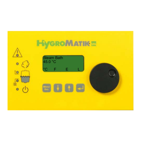
Controls
Brand:
HygroMatik
| Category:
Humidifier
| Size: 3 MB
Table of Contents
Table of Contents
3
1 Introduction
5
Typographic Distinctions
5
Documentation
5
Symbols in Use
6
Specific Symbols Related to Safety Instructions
6
Intended Use
6
2 Safety Instructions
8
Guidelines for Safe Operation
8
General
8
Unit Control
8
Unit Operation
8
Mounting, Installation, Maintenance, Repair and Dismantling of the Unit
9
Electrical
10
3 Comfort- DS / Comfort Plus- DS
11
General View of DS-Control and Operating Panel
11
Communication with the Control
12
Function Keys
12
DS-Comfort and DS-Comfort Plus Compared
13
4 User Mode - Communication with the Control (Comfort-DS/ Comfort Plus-DS)
14
Changing Steam Bath Parameters in User Mode
14
Modifying the Temperature Set Value (G2)
14
Steam Bath Exhaust Fan (D1)
15
Essence Delivery System - Function (D2)
15
Light - Function
16
Overview of Steam Bath Operation and Installation
16
Steam Bath Installation (Schematic Layout)
17
Steam Bath - Temperature Control
18
Temperature Profile in Steam Bath Diagram
19
5 Operating Mode - Advanced Communication with the Control (Comfort-/Comfort Plus-DS)
20
Introduction to the Comfort- DS / Comfort Plus-DS Control
20
Software Menu and Parameter Setting
22
Access to Operating Mode
24
Function Keys
25
Operating Mode - Description of Accessible Parameters
25
Language Menu
26
Start-Up Menu
26
Control Parameters Submenu (under Startup Menu)
27
System Test Submenu (under Startup Menu)
29
Electronic Name Plate Menu
31
Parameter Setting Menu
32
6 Parameters
33
Summary Table of Parameters
33
Explanation of Parameters
35
Steam Bath Functions
35
Steam Bath Mode D0 (Operating Mode)
35
Exhaust Fan D1 (Operating Mode)
36
Essence D2 (Operating Mode)
36
Light D3 (Operating Mode)
37
Supply Fan D4 (Operating Mode)
37
Limitation of Operating Time D5
37
Steam Bath Parameters (G0 - G9, G13)
38
Calibration °C Actual °C (G0)
38
Hysteresis Controller (G1)
38
Steam Bath °C Set Value (G2)
38
Hysteresis Exhaust Fan (G3)
40
Time Essence Injection (G4)
40
Interval Time Essence Injection (G5)
40
Hysteresis Essence Injection (G6)
41
Hysteresis °C Max (G7)
41
Fan Run-On Time (G8)
41
Power Retention (G9)
41
Hysteresis Supply Fan (G13)
41
Humidifier Operating Parameters
42
T0 Timer Mode (Only Available with Comfort Plus-DS Control)
47
Values and Operational Conditions
49
7 Basic- DS
51
Basic Construction
51
Basic-DS Display Unit
51
Basic-DS Main PCB
52
Parameter Setting with Jumpers
52
Brief Description of Jumpers
53
Explanation of Jumper Functions
54
Description of Potentiometer
57
Potentiometer P1 / Steam Generation Output Limitation
57
Potentiometer P2 / Pump Run Time
57
Potentialfree Outputs
57
Collective Fault - Base Relay
57
Humidification
58
Signal Output
58
8 Fault Messages (Comfort- DS / Comfort Plus- DS und Basic- DS)
59
9 For the Installer
62
Temperature Sensor Installation
62
Temperature Sensor Connection
62
Installation of Essence Injector with Peristaltic Pump (Optional)
63
Connection for Essence Injector with 24V Peristaltic Pump Type EP24 (Optional)
64
Fan Installation (Optional)
64
Connection for 24V Steam Bath Exhaust Fan (Optional)
65
Connection for 24V Steam Bath Supply Fan (Optional)
65
Cabin Light Installation (Optional)
65
Cabin Light Connection (Optional)
65
Remote Switch / Safety Interlock
66
10 Potential Free Signal Outputs
67
Base Relay and Signal Relay PCB Capacity
67
Base Relay and Collective Fault
67
Signal Relay PCB and Steam Bath Functions
67
11 Commissioning
69
12 Faults and Messages / Conditions
71
13 Basic PCB Connections
79
14 Terminal Assignments on the Unit Connector Strip and Wiring Diagram Legend
81
15 Wiring Diagram
82
16 Ordering Information / Table of Options
97
17 Technical Specifications
100
Advertisement
HygroMatik Basic-DS Manual (98 pages)
Controls
Brand:
HygroMatik
| Category:
Humidifier
| Size: 2 MB
Table of Contents
Table of Contents
3
1 Introduction
6
Typographic Distinctions
6
Documentation
6
Directions for Use
7
2 Safety Notes
8
Overview
8
Guidelines for Safe Operation
8
General
8
Unit Control
8
Unit Operation
9
Mounting, Dismantling, Maintenance and Repair of the Unit
9
Electrical
10
Disposal after Dismantling
10
3 Comfort- DS / Comfort Plus- DS
11
General View of DS-Control and Operating Panel
11
Communication with the Control
12
Function Keys
12
DS-Comfort and DS-Comfort Plus Compared
13
4 User Mode - Communication with the Control (Comfort-DS/ Comfort Plus-DS)
14
Changing Steam Bath Parameters in User Mode
14
Modifying the Temperature Set Value (G2)
14
Steam Bath Exhaust Fan (D1)
15
Essence Delivery System - Function (D2)
15
Light - Function
15
Overview of Steam Bath Operation and Installation
16
Steam Bath Installation (Schematic Layout)
17
Steam Bath - Temperature Control
18
Diagramm Temperature Profile in Steam Bath
19
5 Operating Mode - Advanced Communication with the Control (Comfort-/Comfort Plus-DS)
20
Introduction to the Comfort- DS / Comfort Plus-DS Control
20
Software Menu and Parameter Setting
22
Access to Operating Mode
24
Function Keys
25
Operating Mode - Description of Accessible Parameters
25
Language Menu
26
Start-Up Menu
26
Control Parameters Submenu (under Startup Menu)
27
System Test Submenu (under Startup Menu)
29
Electronic Name Plate Menu
31
Parameter Setting Menu
32
6 Parameters
33
Summary Table of Parameters
33
Explanation of Parameters
35
Steam Bath Functions
35
Steam Bath Mode D0 (Operating Mode)
35
Exhaust Fan D1 (Operating Mode)
36
Essence D2 (Operating Mode)
36
Light D3 (Operating Mode)
37
Supply Fan D4 (Operating Mode)
37
Limitation of Operating Time D5
37
Steam Bath Parameters (G0 - G9, G13)
38
Calibration °C Actual °C (G0)
38
Hysteresis Controller (G1)
38
Steam Bath °C Set Value (G2)
38
Hysteresis Exhaust Fan (G3)
40
Time Essence Injection (G4)
40
Interval Time Essence Injection (G5)
40
Hysteresis Essence Injection (G6)
41
Hysteresis °C Max (G7)
41
Fan Run-On Time (G8)
41
Power Retention (G9)
41
Hysteresis Supply Fan (G13)
42
Steambath Operating Parameters
43
Values and Operational Conditions
50
7 Basic- DS
52
Basic Construction
52
Basic-DS Display Unit
52
Basic-DS Main PCB
53
Parameter Setting with Jumpers
53
Brief Description of Jumpers
54
Explanation of Jumper Functions
55
Description of Potentiometer
58
Potentiometer P1 / Steam Generation Output Limitation
58
Potentiometer P2 / Pump Run Time
58
Potentialfree Outputs
58
Collective Fault - Base Relay
58
Humidification
59
Signal Output
59
8 Fault Messages (Comfort- DS / Comfort Plus- DS und Basic- DS)
60
9 For the Installer
63
Temperature Sensor Installation
63
Temperature Sensor Connection
63
Installation of Essence Injector with Peristaltic Pump (Optional)
64
Electrical Connection Peristaltic Pump
64
Fan Installation (Optional)
66
Connection for 24V Steam Bath Exhaust Fan (Optional)
66
Connection for 24V Steam Bath Supply Fan (Optional)
66
Connection for 230V Steam Bath Fans (Optional)
67
Cabin Light Installation (Optional)
67
Cabin Light Connection (Optional)
67
Connection for 230V Exhaust/Supply Fan for Steam Generators Type C01 and C02
68
Switch/Safety Interlock
69
10 Potential Free Signal Output
71
Base Relay and Signal Relay PCB
71
Base Relay and Collective Fault
71
Signal Relay PCB and Steam Bath Operation
71
11 Initial Operation
73
12 Faults and Messages / Conditions
74
13 Basic PCB Connections
83
14 Terminal Assignments on the Unit Connector Strip and Wiring Diagram Legend
85
15 Wiring Diagram
86
16 Ordering Information / Table of Options
94
17 Technical Specifications
97
HygroMatik Basic-DS Manual (98 pages)
Steam humidifier
Brand:
HygroMatik
| Category:
Humidifier
| Size: 3 MB
Table of Contents
Table of Contents
3
1 Introduction
6
Typographic Distinctions
6
Documentation
6
Directions for Use
7
2 Safety Notes
8
Overview
8
Guidelines for Safe Operation
8
Disposal after Dismantling
9
3 Comfort- DS / Comfort Plus- DS
10
General View of DS-Control and Operating Panel
10
Communication with the Control
11
Function Keys
11
DS-Comfort and DS-Comfort Plus Compared
12
4 User Mode - Communication with the Control (Comfort-DS/ Comfort Plus-DS)
13
Changing Steam Bath Parameters in User Mode
13
Modifying the Temperature Set Value (G2)
13
Steam Bath Exhaust Fan (D1)
14
Essence Delivery System - Function (D2)
14
Light - Function
15
Overview of Steam Bath Operation and Installation
15
Steam Bath Installation (Schematic Layout)
17
Steam Bath - Temperature Control
18
Diagramm Temperature Profile in Steam Bath
20
5 Operating Mode - Advanced Communication with the Control (Comfort-/Comfort Plus-DS)
21
Introduction to the Comfort- DS / Comfort Plus-DS Control
21
Software Menu and Parameter Setting
23
Access to Operating Mode
25
Function Keys
26
Operating Mode - Description of Accessible Parameters
26
Language Menu
27
Start-Up Menu
27
Control Parameters Submenu (under Startup Menu)
28
System Test Submenu (under Startup Menu)
30
Electronic Name Plate Menu
32
Parameter Setting Menu
33
6 Parameters
34
Summary Table of Parameters
34
Explanation of Parameters
36
Steam Bath Functions
36
Steam Bath Mode D0 (Operating Mode)
36
Exhaust Fan D1 (Operating Mode)
37
Essence D2 (Operating Mode)
37
Light D3 (Operating Mode)
38
Supply Fan D4 (Operating Mode)
38
Limitation of Operating Time D5
38
Steam Bath Parameters (G0 - G9, G13)
39
Calibration °C Actual °C (G0)
39
Hysteresis Controller (G1)
39
Steam Bath °C Set Value (G2)
39
Hysteresis Exhaust Fan (G3)
41
Time Essence Injection (G4)
41
Interval Time Essence Injection (G5)
41
Hysteresis Essence Injection (G6)
42
Hysteresis °C Max (G7)
42
Fan Run-On Time (G8)
42
Power Retention (G9)
42
Hysteresis Supply Fan (G13)
43
Steambath Operating Parameters
44
Values and Operational Conditions
51
7 Basic- DS
53
Basic Construction
53
Basic-DS Display Unit
53
Basic-DS Main PCB
54
Parameter Setting with Jumpers
54
Brief Description of Jumpers
55
Explanation of Jumper Functions
56
Description of Potentiometer
59
Potentiometer P1 / Steam Generation Output Limitation
59
Potentiometer P2 / Pump Run Time
59
Potentialfree Outputs
59
Collective Fault - Base Relay
59
Humidification
60
Signal Output
60
8 Fault Messages (Comfort- DS / Comfort Plus- DS und Basic- DS)
61
9 To the Installer
64
Temperature Sensor Installation
64
Temperature Sensor Connection
64
Installation of Essence Injector with Peristaltic Pump (Optional)
65
Electrical Connection Peristaltic Pump
65
Fan Installation (Optional)
67
Connection for 24V Steam Bath Exhaust Fan (Optional)
68
Connection for 24V Steam Bath Supply Fan (Optional)
68
Connection for 230V Steam Bath Fans (Optional)
68
Cabin Light Installation (Optional)
68
Cabin Light Connection (Optional)
68
Connection for 230V Exhaust/Supply Fan for Steam Generators Type C01 and C02
69
Remote Switch / Safety Interlock
70
10 Potential Free Signal Output
71
Base Relay and Signal Relay PCB
71
Base Relay and Collective Fault
71
Signal Relay PCB and Steam Bath Operation
71
11 Initial Operation
73
12 Faults and Messages / Conditions
74
13 Basic PCB Connections
83
Terminal Assignments on the Unit Connector Strip and Wiring Diagram Legend
85
Wiring Diagram
86
Ordering Information / Table of Options
94
Technical Specifications
97
Advertisement
Advertisement
Related Products
HygroMatik Basic
HygroMatik B-DS
HygroMatik C-DS
HygroMatik C01 KIT
HygroMatik C02 KIT
HygroMatik C06 KIT
HygroMatik C10 KIT
HygroMatik C17 KIT
HygroMatik C30 KIT
HygroMatik C45 KIT
HygroMatik Categories
Humidifier
Electric Heater
Fan
Water Dispenser
Remote Control
More HygroMatik Manuals
Login
Sign In
OR
Sign in with Facebook
Sign in with Google
Upload manual
Upload from disk
Upload from URL