
Related Manuals for HygroMatik Basic-DS


Summary of Contents for HygroMatik Basic-DS
- Page 1 Manual Controls Basic- DS Comfort- DS Comfort Plus- DS Steam Bath 45.0 °C °C Steam Bath 45.0 °C °C ÁDS.ENLÈ DS.EN E-8881116 READ AND SAVE THESE INSTRUCTIONS!
- Page 2 Current version of this manual can be found at: www.hygromatik.co.uk HygroMatik GmbH grants the legal user of this product [or device] the right to use the Work(s) solely within the scope of the legitimate operation of the product [or device]. No other right is granted under this licence.
-
Page 3: Table Of Contents
1. Introduction ............................6 1.1 Typographic Distinctions ........................6 1.2 Documentation ..........................6 1.3 Directions for Use ..........................7 2. Safety Notes ............................. 8 2.1 Overview ............................8 2.2 Guidelines for Safe Operation ......................8 2.2.1 General ............................8 2.2.2 Unit control ............................ 8 2.2.3 Unit operation .......................... - Page 4 6.2.3.1 Values and Operational Conditions .................... 50 7. Basic- DS ............................52 7.1 Basic Construction ........................... 52 7.1.1 Basic-DS Display Unit ........................52 7.2 Basic-DS Main PCB ........................53 7.3 Parameter Setting with Jumpers ...................... 53 7.3.1 Brief Description of Jumpers ......................54 7.3.2 Explanation of Jumper Functions ....................
- Page 5 13. Basic PCB Connections ........................ 83 14. Terminal Assignments on the Unit Connector Strip and Wiring Diagram Legend ....85 15. Wiring Diagram ..........................86 16. Ordering Information / Table of Options ..................94 17. Technical Specifications ....................... 97 Page 5...
-
Page 6: Introduction
They will impress you with their safety, ease of use and economical operation. In order to operate your HygroMatik steam humidifier safely, properly and efficiently, please read these operating instructions. Employ your steam humidifier only in sound condition and as directed. -
Page 7: Directions For Use
1.3 Directions for Use The HygroMatik steamgenerator serves for steam production based on tap water or partially softened water (valid for all of the HygroMatik humidifier models). With the HeaterLine familiy of products, also fully desalinated water/cleaned condensate may be used. -
Page 8: Safety Notes
2. Safety Notes 2.1 Overview These safety notes are required by law. They promote workplace safety and accident prevention. In this document, the following signal words are used for hazard classification: DANGER indicates a hazardous situation which, if not avoided, will result in death or serious injury. -
Page 9: Unit Operation
2.2.4 Mounting, dismantling, maintenance and repair of the unit The HygroMatik steam humidifier is IP20 protected. Make sure that the unit is not object to dripping water in the mounting location. When installation is made in a room without a drain, safety precautions must be taken in order for to shut off the humidifier‘s water supply in... -
Page 10: Electrical
Use genuine spare parts only. After any repair work, have qualified personnel check the safe opera- tion of the unit. Attaching or installing of additional components is permitted only with the written consent of the manufacturer. 2.2.5 Electrical Hazardous electrical voltage! Any work on the electrical system may only be performed by qualified personnel. -
Page 11: Comfort- Ds / Comfort Plus- Ds
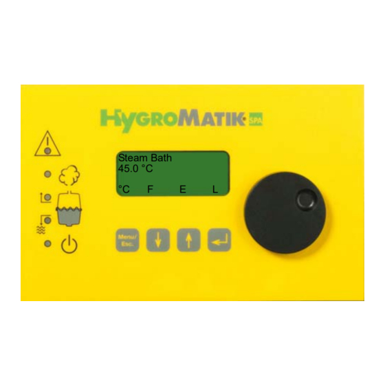
3. Comfort- DS / Comfort Plus- DS The display and operating panel enables local communication with the steam generator. 3.1 General View of DS-Control and Operating Panel DS-Control Display and Operating Panel The display is supplied as a four-line, lighted LC-display. Once the humidifier is switched on, it shows: 1st Line: Operating mode of the steam bath steam generator and sta- Steam Bath... -
Page 12: Communication With The Control
LED colors: yellow yellow yellow green A: Malfunction B: Steady LED = humidification; blinking LED = maximum water C: Filling D: Blow-Down E: Steady LED = ready; blinking LED = maintenance interval 3.2 Communication with the Control Local communication with the Comfort / Comfort Plus control (data input and output) is possible using the display and keypad. -
Page 13: Ds-Comfort And Ds-Comfort Plus Compared
3.3 DS-Comfort and DS-Comfort Plus Compared Comfort- DS Comfort Plus- DS Encoder Knob Unlike the DS-Comfort, the DS-Comfort Plus is equipped with an addi- tional encoder knob for easy use. Turning the knob left or right is equivalent to pressing the software keys “up arrow“... -
Page 14: User Mode - Communication With The Control (Comfort-Ds/ Comfort Plus-Ds)
4. User Mode - Communication with the Con- trol (Comfort-DS/ Comfort Plus-DS) After switching on the steam humidifier, the user is placed in user mode. This mode includes the indicators and controls needed to modify the following parameters: Temperature Set Value °C - (Key Steam Bath Fan Function... -
Page 15: Steam Bath Exhaust Fan (D1)
Steam Bath Steam Bath » Press once. 45 °C 42 °C 42 °C Menu Menu The new temperature set value is programmed. After a few seconds, the program jumps back to the standard display. The display again indicates the active cabin temperature. Concerning Parameter G2, also see Section “Steam Bath Parameters Please note (G0 - G9, G13)”... -
Page 16: Overview Of Steam Bath Operation And Installation
Light control, fan control and essence injection control are optional Please note accessories. HygroMatik steam bath systems are available either in 24V or 230V versions. Risk of electrical shock hazard! Inside the steam cabin, safe low voltage (24V) for the fan and light is a must. -
Page 17: Steam Bath Installation (Schematic Layout)
4.2.1 Steam Bath Installation (Schematic Layout) Location Designation Steam generator Essence peristaltic pump Essence reservoir Essence line to steam hose T-piece for essence feed into the steam hose Steam hose Steam manifold in steam bath bath supply fan Temperature sensor bath exhaust fan Cabin light The illustration below depicts a schematic layout for a steam bath - it is not an installation... -
Page 18: Steam Bath - Temperature Control
The temperature sensor measures the temperature in the steam bath and is connected to the steam generator. The DS-Comfort or DS-Comfort Plus controls the HygroMatik steam generator according to the temperature reading. The relative humid- ity is not measured since it is always 100% following the heat-up phase. -
Page 19: Diagramm Temperature Profile In Steam Bath
4.2.2.1 Diagramm Temperature Profile in Steam Bath Temperature Profile in Steam Bath Temperature 46.0 °C 45.0 °C 44.0 °C Time Steam Production Steam Bath Exhaust Steam Bath Supply Essence Delivery A: Duration / Essence Delivery B: Interval / Essence Delivery ein / on aus / off Page 19... -
Page 20: Operating Mode - Advanced Communication With The Control (Comfort-/Comfort Plus-Ds)
Control Type DS-Comfort and DS-Comfort Plus are explained below in detail. Both the HygroMatik Comfort Control and the Comfort Plus consist of a main PCB and a display unit with back-lighted display, as well as an LED with icons and keys for direct communication with the control. - Page 21 LED colors: yellow yellow yellow green A: Malfunction B: LED steady = humidification; LED blinking = maximum water C: Filling D: Blow-Down E: LED steady = ready; LED blinking = maintenance interval The green LED blinks when the service interval has expired, and “Ser- vice”...
-
Page 22: Software Menu And Parameter Setting
5.2 Software Menu and Parameter Setting System Desired test Temperature Value System settings Power Parameters Page 22... - Page 23 Local communication (data entry and readout) is possible with the Comfort / Comfort Plus Control using the display and the keypad. The most important types of communication are: • Readout/Modification of steam bath operational values (in User Mode) • Selection of the active language (in Operating Mode) •...
-
Page 24: Access To Operating Mode
5.2.1 Access to Operating Mode After switching on the steam humidifier, the user is placed in user mode. The display shows the following: Steam Bath Display 41,5 °C °C User Mode Function When the key is pressed, the software key “°C” is activated and the following display appears: Steam Bath 41,5 °C... -
Page 25: Function Keys
5.2.2 Function Keys Keys are located below the display. Above each key, a context-based action (software key) is shown on the lowest line of the display (i.e. an “°C” key). The action is performed by press- ing the key. The software keys in the display unit enable parameter modification. -
Page 26: Language Menu
5.3.1 Language Menu In this menu, you can select the language in which you communicate with the humidifier. Sprache / Language German English French Spanish Japanese Italian Programming sequence to modify the language: press in Operating Mode, Sprache/Language Sprache/Language select the desired language with and confirm with English Exit the language menu with... -
Page 27: Control Parameters Submenu (Under Startup Menu)
5.3.2.1 Control Parameters Submenu (under Startup Menu) Summary of Parameters: Para- Description Possible Settings Access Code meter Controls 1 Step (On/Off) MODBUS Mehrstufig internal PI-controller Steam generation 25-100% output limiter [%] Xp-PI-controller [0- 100 %] =100/E1 [Amplification] Tn-PI-controller [0- 255sec.] [Integration time] * Only when internal PI-controller is activated Programming sequence to modify the control parameters. - Page 28 Operation Mode » press Parameters Output limit » press until Parameter U6 is displayed P1: 100% Operation Mode » press U6: internal PI controller Operation Mode » press to select “1-step” U6: 1-step Operation Mode » confirm with U6: 1-step Operation Mode »...
-
Page 29: System Test Submenu (Under Startup Menu)
5.3.2.2 System Test Submenu (under Startup Menu) This test enables checks of various humidifier functions (for example, during start-up). The following test routines can be executed: System Test Automatic System Test (includes all stand-alone tests) LED Test (stand-alone test) Pump/MV test (stand-alone test) Control Status Test (stand-alone test) To select the “System Test”... - Page 30 Sample Display Status Solenoid valve out of order or no Test Valve / Pump water supply; also see Section: “Mal- Fault Filling functions and Messages”. Fault Fill- ing. Blow-down pump out of order; also Test Valve / Pump see Section: “Malfunctions and Mes- Blow-Down Fault sages”.
-
Page 31: Electronic Name Plate Menu
5.3.3 Electronic Name Plate Menu The display can show 6 different sets of unit data. Electronic Name Plate Cylinder number Nominal capacity [kg/h] Software version Model type Year of manufacture Serial number S10 Equipment designation » press in Operating Mode, press in Operating Mode, Sprache/Language... -
Page 32: Parameter Setting Menu
5.3.4 Parameter Setting Menu Parameters partly determine the humidifier’s sequence of operations and processing of signals. These parameters can be modified as needed. For security reasons, access to some parameters is protected by an entry code. Two separate access levels have been defined: •... -
Page 33: Parameters
6. Parameters 6.1 Summary Table of Parameters Para- Designation Possible Settings in Menu / Submenu Access Code meter Standby Blow-down 0 Min. - 999 Hours[ HHH : MM Parameter Setting/Blow- none Down Parameters Stand-By heating No/Yes Start-up/System settings Interval time A17 0 - 999 min. - Page 34 Para- Designation Possible Settings in Menu / Submenu Access Code meter 2. Transmitting relay same options as with E5, sta- Parameter Setting / Data tus 14 = factory setting Parameters 3. Transmitting relay same options as with E5, sta- Parameter Setting / Data tus 13 = factory setting Parameters 4.
-
Page 35: Explanation Of Parameters
Para- Designation Possible Settings in Menu / Submenu Access Code meter Parity 8-N-1 Parameter Setting/ Data 8-E-1 Parameters Timer mode Switch On and Switch Off Parameter Setting/Time Times (weekly, daily, off) Clock (only with Comfort Plus) Pumping without K1 Yes (Main Contactor=off) Parameter Setting/Blow- No (Main Contactor=on) Down Parameters... -
Page 36: Exhaust Fan D1 (Operating Mode)
6.2.1.2 Exhaust Fan D1 (Operating Mode) Possible Settings: - Automatic - On (Continuous Operation) - Off Automatic At this setting, fan operation is a function of the temperature in the steam bath. The control switches the exhaust fan on when the desired temperature is reached, and switches it off again when the tempera- ture falls below the set value minus hysteresis. -
Page 37: Light D3 (Operating Mode)
6.2.1.4 Light D3 (Operating Mode) Possible Settings: - On - Off At this setting, the control continuously powers the cabin light. The letter L appears in the display and l changes to L on the 4th line. At this setting, the cabin light remains off. 6.2.1.5 Supply Fan D4 (Operating Mode) Possible Settings: - Automatic... -
Page 38: Steam Bath Parameters (G0 - G9, G13)
6.2.2 Steam Bath Parameters (G0 - G9, G13) Note: Steam bath Parameters G0 - G9 and G13 can only be accessed on the parameter lists with a code (Code 010). 6.2.2.1 Calibration °C Actual °C (G0) Using this Parameter, one can calibrate the temperature sensor con- nected to terminals 6 and 7. - Page 39 Modifying set Temperature Value (G2) Note: The temperature may be modified in increments of 1°K in the main menu. Example: The desired temperature value should be reduced from 45 °C to 42 °C. To do this, proceed as follows: » press in Operating Mode Sprache / Language...
-
Page 40: Hysteresis Exhaust Fan (G3)
Steam Bath °C Set Value » Finish entry of value with G2: 042 °C Steam Bath °C Set Value » Press twice to exit the submenu G2: 42 °C Confirm change with Enter » the modification must be confirmed to be permanently saved; to do this press Parameter Settings »... -
Page 41: Hysteresis Essence Injection (G6)
6.2.2.7 Hysteresis Essence Injection (G6) With this parameter, you set the cabin temperature at which essence delivery is enabled. The essence system is released to operate at a temperature value of Steam Bath °C Set Value (G2) - Hysteresis Essence Injection (G6). Example: G2 is set to 45 °C and G6 is set to 25 K. -
Page 42: Hysteresis Supply Fan (G13)
Power retention is intended as compensation for a cooling sensation Please note due to continuous fresh air supply. The preset value is 0 %. 6.2.2.11 Hysteresis Supply Fan (G13) The fan is activated until the programmed value Steam Bath °C Set Value (G2) + Hysteresis Supply Fan (G13) is reached. -
Page 43: Steambath Operating Parameters
6.2.3 Steambath Operating Parameters P1 Output Limitation The steam output can be set to a value between 25% and 100% of nominal capacity using the steam generation output limitation. The actual steam output released depends on the control signal. Limitation of the steam output may be needed for better control. Example: The steam generation output limitation should be reduced from P1 = 100% (factory setting) to P1 = 70%. - Page 44 Steam Generation » the cursor is now located below the 2nd. digit, press Output Limitation P1: 000% times to set the 2nd. digit to 7; then press Steam Generation Output Limitation P1: 070% » now the cursor is located below the 3rd digit, press finish modifying P1 Steam Generation Output Limitation...
- Page 45 Parameter Settings Code 010 » press Maintenance Parameters » press Maintenance interval P2: 3:00 » press Reset maintenance » press Interval P3: No Reset Maintenance Interval P3: No » press Reset Maintenance Interval P3: Yes » press » Reset Maintenance Interval »...
- Page 46 A17 Stand-by heating The stand-by heating keeps the cylinder water warm when no request is pending. The heating takes place if the safety chain is closed at intervals according to parameter C16 for the interval time A17 and according to parameter C17 for the on time A17. C16 Interval time A17 The C16 parameter defines the length of the pause time between the phases of the stand-by heating (active only if A17 = Yes).
- Page 47 H12 Time Partial Blow-Down (only for HeaterLine Type humidifiers) With this parameter, you set the pump run time during partial blow- down. This is given as a specified blow-down time in seconds. The pre- set value should only be modified in consultation with HygroMatik. Page 47...
- Page 48 P11 Reset service contactor Reset main contactor interval After the preprogrammed number of operations of the main contactor (K1) the HygroMatik control provides the message "Maintenance K1". It is recommended to swap the main contactor and to put the message back.
- Page 49 Changing the system date corresponds to the operating sequence for the system time. Setting the Timer Mode There are three possible settings for the time clock: • off: time clock is disabled • weekly: every day the steam generator is released for the same period of time •...
-
Page 50: Values And Operational Conditions
6.2.3.1 Values and Operational Conditions If the operating mode is set to “with status” using Parameter D0 (see page 38), the operational conditions below are displayed in the 1st line of the display and a readout value is displayed in both the 2nd and 3rd lines. - Page 51 Humidifying/Heating up The steam humidifier produces steam if a demand from the hygrostat or controller is present (safety interlock must be closed). After a humid- ifier cold start-up, or after a full blow-down, Heating up displays for a short time. The display reads Humidifying only after the first refill. Stand-By The safety interlock is open.
-
Page 52: Basic- Ds
The HygroMatik control Type Basic-DS consists of a main PCB and a display unit with icons to describe the LED. 7.1.1 Basic-DS Display Unit Using 5 LED, the display unit of the Basic-DS Control provides the user with information about operational conditions and fault messages: Page 52... -
Page 53: Basic-Ds Main Pcb
7.3 Parameter Setting with Jumpers Normally, settings (parameters) for the Basic-DS Control can only be modified using jumpers. Jumpers are small blocks with two pins over which a circuit plug can be placed, creating an electrical contact inside the plug. -
Page 54: Brief Description Of Jumpers
The jumper is referred to as “open” if there is no plug on either pin or if only one of the pins is covered. Change jumper settings only when the system is turned off! Disregard may result in damage to the control or unpredictable behavier The jumper strip JP1 has 12 jumper positions, designated by the let- ters A to L. -
Page 55: Explanation Of Jumper Functions
If less conductive feed water is used ( = lower salt content), it may be advisable to perform partial blow-downs less often to ensure that the humidifier always attains nominal steam output efficiently (only applies to electrode steam humidifiers). Before modifying this parameter, please consult with HygroMatik. Page 55... - Page 56 Before modifying this parameter, please consult with HygroMatik. Jumper H / Full Blow-Down Switched Off If this jumper is jumpered, the “full blow-down switched off” function is active.
- Page 57 Jumper E and J inverted After the preprogrammed number of operations of the main contactor (K1) the HygroMatik control provides the message "Maintenance K1". During this, the green LED blinks rapidly. By appropriately setting of the jumpers, this message can be reset. Therefore please turn off the unit and identify the status (open or closed) of the jumpers E and J.
-
Page 58: Description Of Potentiometer
The rated load of the relay contact is 250V/8A. 7.3.4.1 Collective Fault - Base Relay The Basic-DS Control is normally supplied with a base relay pro- grammed for a collective fault i.e. the base relay is triggered in case of a malfunction. -
Page 59: Humidification
For an overview of possible fault messages, see Section: “Summary Table of Parameters” on Page 52, description of Parameter E5. The factory setting for the switching signal is “collective fault.” 7.3.4.2 Humidification: The message “humidification” can be accessed directly on the main contactor as specified in the wiring diagram. -
Page 60: Fault Messages (Comfort- Ds / Comfort Plus- Ds Und Basic- Ds)
8. Fault Messages (Comfort- DS / Comfort Plus- DS und Basic- DS) The control Comfort- DS / Comfort Plus- DS and also Basic-DS con- stantly monitor all important functions of the humidifier. In the case of a fault the humidifier switches off. - Page 61 Fault Thermo sensor If a thermo sensor has been tripped, the control registers this with the fault message “Thermo sensor.” Fault Max. Level If the water level in the cylinder reaches maximum five times within a five hour period, the control displays the fault Max. Level. Fault Filling The control activates the solenoid valve for a maximum of 30 minutes.
- Page 62 Fault Main Contactor The control activates the main contactor if steam is required from the humidifier and the safety interlock is closed. The control switches off the main contactor if the safety interlock is open or if steam is no longer required. If the control detects current for a minimum of 15 seconds, even though the main contactor should have been deactivated, the control displays “Fault Main Contactor.”...
-
Page 63: For The Installer
9.2 Temperature Sensor Connection Connect the temperature sensor cable to the designated terminals 6 and 7 on the HygroMatik steam generator. Test using the table below. While the sensor has been calibrated in the factory, subsequent adjustment within a range of -5K to +5K is possible using a 2nd temperature gauge. -
Page 64: Installation Of Essence Injector With Peristaltic Pump (Optional)
EP230 or EP24 can be set at the steam generator. Essence delivery only occurs during steam production. Peristaltic Pump 230V 230V or 24V EP230 Impulse blue black brown Peristaltic Pump EP24 puls brown black grey Steam generator 230V Connection diagram for HygroMatik peristaltic pumps type: EP230 and EP24 Page 64... - Page 65 Connection with 230V Peristaltic Pump type EP230 Lay the connection cable from the peristaltic pump to the steam gener- ator at terminals 17, 18 and 19 (with a 230 V peristaltic pump, see con- nection schematic above). The peristaltic pump is protected by the 1.6A main fuse of the steam generator.
-
Page 66: Fan Installation (Optional)
9.4 Fan Installation (Optional) In any steam bath, an exhaust fan (pos. 10 see on page 17) should be installed. The fan removes warm air from the steam bath in order to ensure continuous steam supply and stable temperature control. Depending on the configuration of the steam bath, an air supply fan (8) can also be operated. -
Page 67: Connection For 230V Steam Bath Fans (Optional)
9.4.3 Connection 230V Steam Bath Fans (Optional) Risk of electrical shock hazard if not observed! Use safe low voltage (24V) for the fans and light in the steam cabin. When employing 230V fans, ensure sufficient distance between the fans and the steam cabin.In the steam generator, connect exhaust fan cable to the designated terminals 20 and 21 (230V) and connect sup- ply fan cable to terminals 20 and 22 (230V). -
Page 68: Connection For 230V Exhaust/Supply Fan For Steam Generators Type C01 And C02
E5 = Zulüfter E5 = Ablüfter E5 = exhaust fan E5 = supply fan (Benennung) (Zeichnung Nr.) Datum 31.05.11 HYGROMATIK Telefax Phone Dampfbadoption 230V für C01 - C02 +49-(0)4193 / 895 - 33 +49-(0)4193 / 895 - 0 Bearb. S-043214 Lise-Meitner-Str. -
Page 69: Switch/Safety Interlock
Factory setting has no wire bridge across terminals 1 and 2. Remote switch For switching the HygroMatik steam generator on and off remotely, a remote switch is to be connected across terminals 1 and 2. With the switch closed the steam generator is operative. When opening the con- tact across terminals 1 and 2, the steam generator ceases operation. - Page 70 Ensure proper contact specification! Contacts must be potential-free and rated for 230 VAC switching. Risk of electrical shock hazard! Within the steam cabin, only save low voltage (24V) may be used. Page 70...
-
Page 71: Potential Free Signal Output
10.1.2 Signal Relay PCB and Steam Bath Operation* The signal relay PCB is optinal attached to the main PCB of the DS- Comfort / Plus Control or the Basic-DS. The signal relay PCB provides four additional signal relays. Each relay is designed to control a speci- fied steam bath component. - Page 72 Please note Do not modify Parameters E6 and E9 except in consultation with HygroMatik, since this could lead to malfunctions. Retrofitting a Signal Relay PCB: Plug the socket connector JP1 of the relay signal PCB into the socket base JP3 on the main PCB, so that the two holes on the signal relay PCB line up with the internal thread bolts (main PCB side).
-
Page 73: Initial Operation
How to switch on the steam generator: » Open supply water shut-off cock. » Switch on unit by means of the control switch. The following functions are executed during the start-up routine: HygroMatik (R) Self Test • The unit performs self-tests. LED Test •... -
Page 74: Faults And Messages / Conditions
12. Faults and Messages / Conditions Switch off the steam humidifier immediately if a fault occurs! Faults are only to be remedied by qualified personnel following the pro- per safety instructions. Please note The Section Fault Messages details which fault messages are possible for which humidifiers. - Page 75 LED Dis- Message / Mal- Probable Cause Resolution play function Dis- played* • Solenoid valve does not close properly. Water • Check solenoid valve. Fault Max.-Level ctd. level in the cylinder rises slowly even though the solenoid valve has not been activated. •...
- Page 76 LED Dis- Message / Mal- Probable Cause Resolution play function Dis- played* • • Fault Main Con- Main contactor does not drop out. Replace main contactor. tactor • • Unit shuts off auto- Relay on the PCB is stuck. Replace PCB. matically •...
- Page 77 Feed a cable through current transducer ring. • Check water values and/or contact - Water conductivity too low. - Cold start. HygroMatik. - Re-start following full blow-down. - Changing water conductivity. • Replace electrodes. - Electrodes worn out • Unit requires maintenance.
- Page 78 • Replace fuse. • With very low water conductivity continuous • Establish water values and/or con- steam production is insufficient in order to tact HygroMatik about the problem. concentrate and raise the water conductivity. • According to manufacturer specification 90% •...
- Page 79 Possible Condi- Probable Cause for fault situation Resolution tions • Hose clamps on the steam or condensate • Tighten hose clamps. Water is leaking from upper part of hose do not close tightly. steam cylinder. • The heater element or thermo sensor has not •...
- Page 80 Possible Condi- Probable Cause for fault situation Resolution tions • • The set tempera- The unit’s steam generation output limitation Check steam generation output ture has not been prevents full output. limitation parameter “P1”. reached. The unit is being operated at “cylinder full” See message Maintenance / •...
- Page 81 Excess pressure in duct system (max. over- ically from the drain • • pressure 1200 Pa) Lengthen drain hose, consult with hose while the HygroMatik if necessary. pump is not run- ning. • Uneven electrode Electrode(s) is/are not supplied with power. wear Breaker has been tripped.
- Page 82 Deactivate the unit immediately to cylinder rapid loss of electrode material (brown-black prevent it from being damaged. deposits) and very high water conductivity. In these cases, consult HygroMatik. Perform maintenance: - Replace electrodes - Clean steam cylinder - Check water quality or conductivity, also see Section „Di-...
-
Page 83: Basic Pcb Connections
13. Basic PCB Connections Main PCB transducer (only Humidifier type HyLine, CompactLine and MiniSteam) fault indicator lamp (red) humidify indicator lamp (yellow) D 63 filling indicator lamp (yellow) blow-down indicator lamp (yellow) operating indicator lamp (green) potentiometer steam generation output limitation; 25 - 100% humidification output potentiometer pump run time 0 - 45 sec. - Page 84 Page 84...
-
Page 85: Terminal Assignments On The Unit Connector Strip And Wiring Diagram Legend
14. Terminal Assignments on the Unit Con- nector Strip and Wiring Diagram Legend Unit Connector Strip: Terminals Assignment 1 / 2 Remote Switch / Safety Interlock 6 / 7 Temperature Sensor 8 / 9 / 13 Essence Injector max. 70 W / 24 V / 3,15 A 10 / 11 Exhaust Fan max. -
Page 86: Wiring Diagram
15. Wiring Diagram Page 86... - Page 87 Page 87...
- Page 88 Page 88...
- Page 89 HL 12 / HL 18 HL 27 / HL18 Betriebsmeldung Betriebsmeldung operation operation Halbleiterrelais an der solid state relay Halbleiterrelais an der solid state relay Geräte-Mittelwand located at middle plate Geräte-Mittelwand located at middle plate R1 - R2 in HL12 KW Heizkörper / heating element R1 - R3 in HL27...
- Page 90 Page 90...
- Page 91 Page 91...
- Page 92 Page 92...
- Page 93 Page 93...
-
Page 94: Ordering Information / Table Of Options
16. Ordering Information / Table of Options Ordering is this simple: Steam generator with exact designation (e.g. HyLine: HY17-CDS) + desired optional connection configurations (e.g. Option 230 V: B-0623093 for C17-C45 or Hy13 -Hy 30) + steam bath accessories with article designation and article number (as needed) Table of Options: Electrode Steam Generator What connections* does your steam generator need ? - Page 95 Steam Bath Accessories: • Peristaltic Pump for Essence 24V B-2604083 • Peristaltic Pump for Essence 230V B-2604091 • Steam Bath Fans, 24V , ø 98mm E-0611205 • Steam Bath Fans, 230V, ø 98mm E-0611208 • T-piece 2 x DN25, 1 x DN6, VA •...
- Page 96 System Desired test Temperature Value System settings Power Parameters Page 96...
-
Page 97: Technical Specifications
17. Technical Specifications Heater Element Steam Generator HL06 HL09 HL12 HL18 HL24 HL27 HL30 HL36 HL45 Type HeaterLine Steam Output [kg/h] Power Rating [kW] 13,5 18,0 20,3 22,5 27,0 33,8 Power Consumption [A] 11,3 16,8 19,5 29,3 39,0 29,3 39,0 58,5 58,5 Circuit Protection [A]... - Page 98 Lise-Meitner-Str.3 • D-24558 Henstedt-Ulzburg Phone +49(0)4193/ 895-0 • Fax -33 eMail hy@hygromatik.de • www.hygromatik.com A member of the Group...
Need help?
Do you have a question about the Basic-DS and is the answer not in the manual?
Questions and answers