
Related Manuals for HygroMatik HyLine Series


Summary of Contents for HygroMatik HyLine Series
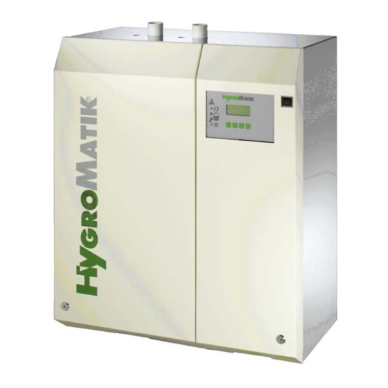
- Page 1 Manual Electrode Steam Humidifier Electrode Steam Humidifier IMPORTANT: READ AND SAVE THESE INSTRUCTIONS ÁHYL.CSA9È HYL.CSA E-8881700...
- Page 2 Current version of this manual can be found at: www.hygromatik.de/us All rights reserved. HygroMatik GmbH grants the legal user of this product [or device] the right to use the Work(s) solely within the scope of the legitimate operation of the product [or device]. No other right is granted under this licence.
-
Page 3: Table Of Contents
1. Introduction ........................5 1.1 Typographic Distinctions ....................5 1.2 Documentation ........................5 1.3 Symbols in Use ......................... 6 1.3.1 Specific Symbols related to Safety Instructions ............. 6 1.3.2 General Symbols ......................6 1.4 Intended Use ........................6 2. Safety Instructions ......................8 2.1 Guidelines for Safe Operation ................... - Page 4 5.6 Unit Installation Check ....................... 35 6. Water Installation ......................36 6.1 Operation with Softened Water ..................37 6.2 Water Supply ........................38 6.3 Water discharge ........................ 39 6.4 HyFlow Provision (Special order unit types) ..............40 6.5 Water Installation Checklist ....................41 7.
-
Page 5: Introduction
Thank you for choosing a HygroMatik steam humidifier. HygroMatik steam humidifiers represent the latest in humidifica- tion technology. In order to operate your HygroMatik steam humidifier safely, pro- perly and efficiently, please read these operating instructions. Employ your steam humidifier only in sound condition and as directed. -
Page 6: Symbols In Use
The HygroMatik steamgenerator serves for steam production based on various water qualities or partially softened water (valid for all of the HygroMatik humidifier models). With the Hea- terLine, HeaterCompact/Kit and HeaterSlim familiy of products, also fully desalinated water/cleaned condensate may be used. - Page 7 You should place a copy of the Operation and Maintenance Instructions at the unit‘s operational location (or near the unit). By construction, HygroMatik steam humidifiers are not qua- lified for exterior application. Risk of scalding! Steam with a temperature of up to 212 °F is produced.
-
Page 8: Safety Instructions
2. Safety Instructions These safety instructions are required by law. They promote workplace safety and accident prevention. 2.1 Guidelines for Safe Operation 2.1.1 General Comply with the accident prevention regulation „DGUV Regula- tion 3“ to prevent injury to yourself and others. Beyond that, national regulations apply without restrictions. -
Page 9: Mounting, Maintenance, Repair And Dismantling Of The Unit
Do not remove or disable safety devices 2.1.4 Mounting, maintenance, repair and dismantling of the unit The HygroMatik steam humidifier is IP20 protected. Make sure that the unit is not object to dripping water in the mounting loca- tion. When installation is made in a room without a drain, safety pre- cautions must be taken in order for to shut off the humidifier‘s... -
Page 10: Transport
3. Transport 3.1 Overview Please note Proceed carefully when transporting the steam humidifier in order to prevent damage due to stress or careless loading and unloading. 3.2 Carton outer Size and Weight HyLine: Type* Height Width Depth Weight [cm]/[inch] [cm]/[inch] [cm]/[inch] [kg]/[lbs] HY05- 08... -
Page 11: Packing
3.3 Packing Please note Notice the symbols affixed to the packing box. 3.4 Interim Storage Store the unit in a dry place and protect against frost. 3.5 Check for Complete and Correct Delivery of Goods Upon receipt of the unit, confirm that: •... -
Page 12: Functional Description And Device Composition
4. Functional description and device compo- sition 4.1 Mode of Operation Electrodes through which electrical current flows heat conduc- tive water in a cylinder to create unpressurized, hygienic steam. Electrode steam humidifiers are suitable for use with normal tap water, as this is normally conductive. The steam produced has a temperature of about 100°C/212°F with minimal excess pressure ("pressureless steam"). -
Page 13: Installation
Unit may drop during mounting involving a single person. Helping hand of a second person is required. Please note HygroMatik accepts no liability for damage due to faulty installa- tion. Please note Attaching or installing additional components is permitted only with the written consent of the manufacturer, or else the war- ranty is void. - Page 14 • Ambient temperature must lie between +41 and +104 °F in order to protect the unit electronics against damage; frost may damage the steam cylinder • Relative humidity must not exceed 80 % r.h., since values beyond may lead to electronic malfunction or damage •...
-
Page 15: Fitting Measures
5.1.1 Fitting measures Clearances > 50mm/ > 200mm/ > 500mm/ > 300mm/ When choosing the site for the steam humidifier, consider the Please note location of existing water installations (feed and drain lines). Mounting Fixtures (for HY45 to HY116) The unit should be mounted on a stable wall. Please note To achieve a uniform immersed surface area for the electrodes, the humidifier must be installed plumb and level. - Page 16 to Install Units Type HY05- HY30: » Place the steam humidifier in its intended location, use a level to adjust position, and secure. See chapter "Unit Dimensions". » Attach the unit to the lower mounting fixtures. to Install Units HY45- HY116: »...
-
Page 17: Unit Dimensions Hy05-Hy45
5.1.2 Unit Dimensions HY05-HY45 View from below Water inlet Waste water connection Cable entries Rear view View from top Steam outlet (1x/2x) Page 17... - Page 18 Type / Dimensions [mm]/ [inch] HY05-HY08 480/ 449/ 251/ 415/ 438/ 120/ 120/ 103/ 147/ 18.9 17.7 16.3 17.2 HY13-HY23 650/ 522/ 301/ 486/ 619/ 210/ 152/ 136/ 184/ 25.6 20.6 11.9 19.1 24.4 HY30 708/ 561/ 344/ 515/ 665/ 250/ 172/ 156/...
-
Page 19: Unit Dimensions Hy60-Hy116
5.1.3 Unit Dimensions HY60-HY116 Cable entries Waste water connection (2x) Water inlet (2x) Steam outlet (2x/4x) Page 19... - Page 20 Type / Dims. [mm]/ d1 d2 d3 [inch] HY60 709/ 927/ 333/ 327/ 371/ 133/ 680/ 368/ 195/ 525/ 186/ 27.9 36.5 13.1 12.9 14.6 26.8 14.5 20.7 7.3. HY90-HY116 788/ 1061 403/ 398/ 398/ 132/ 132/ 758/ 432/ 238/ 635/ 220/ 31.0...
-
Page 21: Fan Units (Options)
5.2 Fan Units (Options) Please note The fan units should be positioned in a way that avoids drafts. In general, a minimum height of 6 ft 7 in (2 m) above floor is suffi- cient. Install the fan unit directly on a wall. Risk of skin burning or scalding! During operation and for at least 10 mins afterwards the steam nozzles are hot. -
Page 22: Fan Unit Cover
5.2.2 Fan Unit Cover Covers for humidifier types HY05 and HY30 are optionally avail- able to protect the steam and condensate hoses between the steam humidifier and the fan unit. The vertical distance between the humidifier and the fan unit is determined by the height of the cover (see table of dimensions, H). -
Page 23: Absorption Distance Bn
5.3 Absorption Distance B The "absorption distance" (B ) is defined as the distance from the steam feed to where the steam is completely absorbed in the treated air. Within the absorption distance, steam is visible as mist in the air stream. Condensation may occur on anything installed within the absorption distance. - Page 24 Length I of the usable steam manifold depends on the dimen- sions of the air duct. The length of the absorption distance can be reduced by using multiple steam manifolds (also see section on the steam manifold). Method: Graphically determine absorption distance B using the absorp- tion distance nomogram (also see Section „Absorption Distance Nomogramm“).
-
Page 25: Absorption Distance Nomogram
5.3.2 Absorption Distance Nomogram Source: Henne, Erich: Luftbefeuchtung (Air Humidification), 3 Edition 1984 (Page 101), Olden- bourg Industrieverlag, Munich Page 25... -
Page 26: Steam Manifold
5.4 Steam Manifold 5.4.1 Guidelines for Installation Positioning within duct • Install the steam manifold as close as possible to the steam humidifier in order to minimize steam loss through condensation • Steam manifold placement on the supply side of the air duct is preferable •... -
Page 27: Recommendations For Dimensioning
5.4.2 Recommendations for dimensioning Horizontal installation of The recommendations given below are based on homogenous steam manifold air flow in the duct. Standard steam manifold arrangement Duct Steam Manifold Air flow L1=L2=L3 An even distribution of steam manifolds ensures a uniform steam distribution. - Page 28 Steam manifold arrangement for special air duct shapings Air duct Positioning of steam manifolds Sample flat Staggered vertically and laterally Air flow very flat By tilting the steam manifold 30 - 45° very flat duct towards the air flow direction, the mini- mum upper clearance can be reduced to 70mm/2.8inch.
- Page 29 Length of steam manifold [mm]/[inch]*: 220/ 400/ 600/ 900/ 1200/ 1450/ 15.7 23.6 35.4 47.2 57.1 DN25/1“ DN40/1 1/2“ * special lenght on request 70mm/ 120mm/ 90mm/ 2.8 inch 4.7 inch 3.5 inch 1,5mm/ 0.06 inch The number and size of appropriate steam manifolds, as well the nominal width of their respective steam and condensate hoses, are found in the tables below.
- Page 30 “ “ * For units HL 6 - 12 delivers one adapter DN40 / 25. ** For units HL 36 - 45 HygroMatik delivers one t-connector for separating the steam on two steam manifold. *** Special lenght on request. Page 30...
-
Page 31: Steam Line And Condensate Hose Layout
HygroMatik hoses only. 5.5.1 Guidelines for steam line design • Steam hose nominal diameter must not be smaller than the steam outlet of the HygroMatik steam humidifier (do not restrict the cross-section, otherwise back pressure will increase) • Steam hoses must be laid without sags and kinks and with a continuous slope of 5-10% (otherwise sags may result). -
Page 32: Condensate Hose Layout
5.5.2 Condensate hose layout The condensate hose may be run from the steam manifold back to the steam cylinder, as depicted in the schematic drawing below with concern to installation type 1. Depending on the par- ticular model, the condensate hose is then connected to a stub on the cylinder top directly (1 condensate hose) or via a T-piece (2 condensate hoses). - Page 33 Steam manifold Steam hose 500 mm 20 inch min. Rmin DN25: 200 mm/8 inch DN40: 400 mm/16 inch Device Steam cylinder upper edge Installation type 1, schematic representation How to connect two condensate hoses to the C45 steam cylin- For connecting two condensate hoses, steam humidifier model C45 delivery comprises a Nylon T-piece.
- Page 34 Installation type 2 Steam manifold is positioned less than 500 mm/20 inch above or below device upper edge: Please note In this arrangement the condensate hose cannot be fed back to the steam humidifier. » Run steam hose to a height of 400 mm/16 inch mini- mum above the steam humidfier and then to the steam manifold with a continous decline of 5 to 10 %.
-
Page 35: Unit Installation Check
5.6 Unit Installation Check Please check the installation using the following list: Does unit hang vertically? Are wall distances to the unit within the range Does steam hose have a slope of 5-10%? Is condensate hose installed with a loop of min. 200 mm/8 inch? ... -
Page 36: Water Installation
6. Water Installation Risk of scalding! Very hot water on the humidifier drain side! Have all installation work done by expert staff in order to avoid scalding hazards due to improper water guidance. Risk of electrical shock! Hazardous electrical high voltage! Before starting installation work make sure that the unit is not connected to the power supply. -
Page 37: Operation With Softened Water
6.1 Operation with Softened Water Do not use softened water unless special measures are taken! When feeding softened water into the HygroMatik steam humidi- fier, the aspects outlined below must be taken into account. Softened water may cause • unacceptably high conductivity •... -
Page 38: Water Supply
In case of no safety device for drinking water protection accord- ing to DIN EN 1717 present in the house installation system, a system separator at least of the CA type is mandatory. Alterna- tively, a HygroMatik steam humidifier special type featuring the HyFlow provision may be used. »... -
Page 39: Water Discharge
Risk of material damage! Excessive tightening will destroy the solenoid fitting thread. Do not overtighten the cap nut. » Screw the other hose end cap nut with its inner seal on a customer-provided water tap (cup nut internal thread is ¾“). 6.3 Water discharge Risk of scalding! During blow down up to .3 l/sec (.08 gal./sec) are being drained... -
Page 40: Hyflow Provision (Special Order Unit Types)
6.4 HyFlow Provision (Special order unit types) HygroMatik HyLine and CompactLine humidifiers are available featuring the certified plastic HyFlow system separator (DVGW CERT AS-0625CP0094 for HyLine, DVWG CERT AS- 0625CP0095 for CompactLine). -
Page 41: Water Installation Checklist
6.5 Water Installation Checklist Verify correct system installation using the checklist below: All screws and clamps been properly tightened? Water supply line carefully flushed out? Water installation performed correctly? Drainage system correctly installed? Flushed-out water can drain freely? Water supply and drain free of leaks? Page 41... -
Page 42: Electrical Connection
7. Electrical Connection Risk of electrical shock! Hazardous electrical high voltage! All work related to electrical installation to be performed by authorized personnel only (electricians or professionals with equivalent training). Please note The customer is responsible for checking qualifications. Do not connect the steam humidifier to the live power sup- ply before all installation work has been completed! General installation rules •... - Page 43 We recommend employing medium blow main fuses. The tables below show input currents and the circuit protection required for the various HygroMatik humidifier models. *) After full blow down, power input is 1.3 times higher than in nor- Please note mal operation.
-
Page 44: Cable Connections
MiniSteam: Technical Specifications Steam Humidifier MiniSteam Model MS05 MS10 Data at 208V/1 Phase, Power Rating [kW] 60 Hz Input Current [A] 2 x 20 2 x 20 Circuit Protection [A]*) Data at 208V/3 Phase, Power Rating [kW] 60 Hz 10.4 16.0 Input Current [A] 3 x 15... -
Page 45: Safety Interlock
7.3 Safety Interlock Please note Install contact interlocks, i.e. max. hygrostat, vane relay, pres- sure controller, air interlock, etc. in series across terminals 1 and 2. Use max.-hygrostat for protection! A max-hygrostat should be installed in the safety interlock. The max-hygrostat acts as a safety device in case the humidity sen- sor malfunctions. - Page 46 (applies only to humidifier types HyLine and MiniSteam). Please note Detailed information concerning initial operation, control, service and malfunctions as well as circuit diagrams can be found in the operation manuals for HygroMatik control units. Page 46...
-
Page 47: Commissioning
8. Commissioning Risk of electrical shock! Hazardous high electrical voltage! Start-up of the unit is restricted to expert staff only (electricians or expert personnel with equivalent training). Step 1: Check of mechanical integrity » Check cylinder seating. » Check steam and condensate hose clamps. Step 2: Check of electrical wire connections »... -
Page 48: Maintenance
9. Maintenance Perform regular maintenance to give your unit a long life span. Inadequate or improper maintenance may cause operational malfunctions. Risk of electrical shock! Unit must be switched off and protected against restart by expert staff (electricians or expert personnel with equivalent training) before any maintenance work is commenced. -
Page 49: Maintenance Work
In extreme cases, water pretreatment may be necessary (softe- ning by dilution to approx. 4 - 8 °dH; decarbonization/partial desalination to achieve target reductions in carbonate hard- ness). HygroMatik would be pleased to refer you to companies specia- lizing in water treatment systems. Page 49... -
Page 50: Access To Electrical Enclosure
9.2 Access to Electrical Enclosure Risk of electrical shock! Hazardous electrical high voltage! Make sure the unit is switched off before installing or removing the display panel. » Remove cover from humidifier (B) and lift display panel (A) off guiding. »... - Page 51 Risk of injuries to the eyes! Cylinder clips may jump off due to pretension. Wear proper PPE (Personal protection equipment)! Risk of cut injuries! Both the clamps that fix the steam cylinder halves and the elec- trodes have sharp edges and angles. Wear proper PPE (Personal protection equipment)! Risk of electrical shock! Hazardous electrical high voltage!
- Page 52 Verify safe isolation Remove stopper Disconnect unit from Completely drain the cylinder water supply Remove steam Check cylinder temperature hose from adapter Push clip on adapter Lift steam cylinder out of base outside cabine Page 52...
- Page 53 Unplug electrodes / Remove flange clamps sensor electrode Remove used O-ring Open cylinder Clean cylinder inside. Do not use acids or other chemicals. Clean strainer » Check the inside of the top part of steam cylinder for crust build-up and possible salt bridges (black grooves between the electrode leads).
- Page 54 Reassembly Connect upper and lower Insert new O-ring part with clamps When re-assembling the cylinder, the joints and reinforcements Please note of both sections must fit together snugly. Insert new O-ring Remove used O-ring Remove old O-ring, insert new O-ring Before the electrode plugs are attached, please make sure that Please note they are free of corrosion.
- Page 55 Ensure proper plug seating on electrodes! The plugs must be pressed down onto the electrodes as far as they will go. Please note Wiring color corresponds with the color of the knurled nut. Please note When reinstalling the steam cylinder, make sure that the con- densate connection shows towards the unit front on the left hand side.
- Page 56 Risk of electrical shock! Hazardous electrical high voltage! Follow safety instructions for work on live equipment. » Switch on unit and monitor for leakage during 15-30 minutes of operating. » In case of leakage switch of unit and redeem lea- kage(s).
-
Page 57: Electrode Wear
This maintenance message will appear after one hour of operation at maximum water level. The humidifier operation will then stop. 9.4.1 Original Electrode Lengths Original lengths of HygroMatik large area stainless-steel elec- trodes are: HyLine: Type... -
Page 58: Uneven Electrode Lengths
Replace electrodes with significantly uneven wear. Check the Please note power supply (circuit breaker, voltage drop). Also see operating manual of the relevant HygroMatik control, section "Faults and Messages." 9.5 Replacing Electrodes remove electrode remove handnut... - Page 59 Loosen knurled nuts (5) and remove electrodes (48). » Install new electrodes and hand tighten the nuts. » Use solvent-free, HygroMatik-quality o-rings (for flange, cylinder base and steam hose adapter). » Assemble steam cylinder and place it into cylinder. »...
-
Page 60: Cleaning The Blow- Down Pump
9.6 Cleaning the blow- down pump The numbers in paranthesis refer to the exploded view figure. » Remove cylinder. » Detach e-cable from pump. » Detach adapter (30) from pump. » Loosen screws (44) and remove pump from base. » Open pump (bayonet lock). -
Page 61: Cleaning The Water Inlet Solenoid Valve And Hyflow System Separator (Special Models Only)
Re-installation » Insert fine mesh filter. » Reinsert solenoid valve with seal in unit housing open- ing an bolt down. » Screw on water installation hose. » Connect electrical cable to solenoid valve. » Attach connecting hose (21) to cylinder base. »... -
Page 62: Checking Cable Connections And Electrode Cables
Re-installation » Reinsert solenoid valve with seal in the unit housing opening and bolt down. » Screw on water supply hose. » Connect electrical cable to the solenoid valve. » Attach HyFlow with screw. » Attach connecting hose (21) to the base. Squeeze the John Guest connections firmly. -
Page 63: Checking Hoses
9.10 Checking Hoses Since steam and condensate hoses are also subject to wear they have to be checked regularly. 9.11 Checking Operation Start up the unit and operate for a few minutes at maximum out- put if possible. » Check safety devices. »... -
Page 64: Dismantling
10. Dismantling Once the steam humidifier will no longer be used, dismantle (demolish or scrap) it by following the installation procedures in reverse order. Warning: Dismantling of the unit may only be performed by qualified personnel. Electrical dismantling may only be per- formed by trained electricians. -
Page 65: Csa Certificate Of Compliance
1887098 Master Contract: 238708 Certificate: 70027121 Date Issued: March 23, 2015 Project: Issued to: Hygromatik GmbH Lise-Meitner Strasse 3 Henstedt-Ulzburg, D-24558 GERMANY Attention: Michael Lutkemann The products listed below are eligible to bear the CSA Mark shown with adjacent indicators 'C' and 'US' for Canada and US or with adjacent indicator 'US' for US only or without either indicator for Canada only. - Page 66 Certificate: 1887098 Master Contract: 238708 70027121 Date Issued: March 23, 2015 Project: APPLICABLE REQUIREMENTS CSA Std C22.2 No. 104-11 (4 Humidifiers UL Std No. 998 (5 Humidifiers DQD 507 Rev. 2012-05-22 Page 2 Page 66...
- Page 67 Supplement to Certificate of Compliance 1887098 Master Contract: 238708 Certificate: The products listed, including the latest revision described below, are eligible to be marked in accordance with the referenced Certificate. Product Certification History Project Date Description 70027121 Mar 23 2015 Update report 1887098 to add new model Series MS and add 230 V Control option.
-
Page 68: Spare Parts
12. Spare Parts HY05 HY13 Article No. Description HY08 HY17 HY23 HY30 HY45 HY60 HY90 HY116 E-2124010 Keys for safety, set=2pc. E-2124012 Safety lock incl. 2 keys Steam generation universal Steam cylinder CY8 compl. with electrodes and hand nuts B-3204031 Steam cylinder CY17 DN 25 compl. - Page 69 HY05 HY13 Article No. Description HY08 HY17 HY23 HY30 HY45 HY60 HY90 HY116 B-3204027 Sensor electrode compl. with hand nut B-2204075 Sensor electrode compl. with hand nut E-3216025 Plug-in contact with isolating hose for sensorelectrode Plug-in contact with isolating hose for steam generating E-3216024 electrodes Plug-in contact with isolating hose for steam generating...
- Page 70 HY05 HY13 Article No. Description HY08 HY17 HY23 HY30 HY45 HY60 HY90 HY116 Steam generation with electrical supply 500V and higer Steam cylinder CY8 compl. with electrodes and hand nuts B-3204033 Steam cylinder CY17 DN 25 compl. with electrodes and B-2206109 hand nuts ** Steam cylinder CY17 DN 40 compl.
- Page 71 HY05 HY13 Article No. Description HY08 HY17 HY23 HY30 HY45 HY60 HY90 HY116 Steam generation with electrical supply between 380 and 480V Steam cylinder CY8 compl. with electrodes and hand nuts B-3204031 Steam cylinder CY17 DN 25 compl. with electrodes and B-2204101 hand nuts ** Steam cylinder CY17 DN 40 compl.
- Page 72 HY05 Article No. Description HY08 HY13 HY23 HY30 HY45 HY60 HY90 HY116 Steam generation with electrical supply 240V or lower Steam cylinder CY8 compl. with electrodes and hand nuts B-3216109 Steam cylinder CY17 DN 25 compl. with electrodes and B-2204101 hand nuts ** Steam cylinder CY17 DN 40 compl.
- Page 73 HY05 HY13 HY08 HY17 HY23 HY30 HY45 HY60 HY90 HY116 Article No. Description Water feed 0,90 1,60 1,60 1,60 1,90 1,60 1,90 1,90 E-2604002 Connecting hose solenoid valve - cylinder base, per m Solenoid valve, servo controlled, straight type, 0,2-10bar, 2,5 l/min. B-2304029 (at 4 bar), 24V Solenoid valve, servo controlled, straight type, 0,2-10bar, 3,5 l/min.
- Page 74 HY05 HY13 Article No. Description HY08 HY17 HY23 HY30 HY45 HY60 HY90 HY116 Control, electrical supply 500V or higher E-2504158 Transformer 690V/230V, 25VA E-2504224 Transformer 210-540V / 24V E-2504220 Transformer 230-400-460-520V / 230V E-2504042 Safety fuse 0,5A E-2590102 Line safety switch, 1 A Connecting cables for electrodes with plug-in contact, B-3526021 set=3pc...
- Page 75 HY05 HY13 Article No. Description HY08 HY17 HY23 HY30 HY45 HY60 HY90 HY116 Control, electrical supply 240V or lower E-2504224 Transformer 210-540V / 24V E-2504220 Transformer 230-400-460-520V / 230V B-2507113 Main contactor 80 A incl. 2 x NO contact, 24V B-2507083 Main contactor 65 A incl.
- Page 76 HY05 HY13 Article No. Description HY08 HY17 HY23 HY30 HY45 HY60 HY90 HY116 B-2120905 Mounting plate (advanced) with foil B-2526401 Display (standard) with mounting plate and foil B-2526403 Display (advanced) with mounting plate and foil E-0605228 Temperature sensor TF104 B-2505207 Holder for temperature sensor TF104 incl.
-
Page 77: Fax Form - Order For Spare Parts
13. Fax Form - Order for spare parts Fax Form Please copy, fill in and fax to HygroMatik GmbH Lise-Meitner-Str. 3 . +49(0)4193/895-31 Fax.No 24558 Henstedt-Ulzburg Tel. +4904193/895-0 Order of spare parts unit type *______________ serial no.* ___________________ commission: ______________ order no.: __________________... - Page 78 This page intentionally left blank Page 78...
-
Page 79: Exploded View
14. Exploded View Special model „HyFlow“ Page 79... -
Page 80: View Of Housing
15. View of housing Page 80... -
Page 81: Technical Specification
16. Technical Specification Technical Specifications Steam Humidifier HyLine (with Basic, Comfort/-Plus control) Type HY05 HY08 HY13 HY17 HY23 Data at 208V/3 Phase, 60 Hz Steam output [kg/h / lbs/h] 5.0 / 11 7.7 / 17 13.0 / 29 14.4 / 32 23.0 / 51 3.75 10.8... - Page 82 Lise-Meitner-Str.3 • D-24558 Henstedt-Ulzburg Phone +49(0)4193/ 895-0 • Fax -33 eMail hy@hygromatik.de • www.hygromatik.com 12/2004 A member of the Group...
Need help?
Do you have a question about the HyLine Series and is the answer not in the manual?
Questions and answers