Advertisement
Quick Links
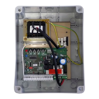
CONTROL UNIT SCOR.AS FOR BARRIERS BEVK
1. Introduction
The control unit SCOR.AS BEVK is suitable for barriers direct current 24V with encoder and a maximum absorption of 7A. The control unit allows a precise
adjusting of the barrier thrust and regulation of the velocity and sensibility on slowing phase. This control unit can memorize up to 30 transmitters and up
to 8000 transmitters with the external memory, with the step by step and pedestrian functions. It is provided with inputs for photocell, rib, opening limit
switch, input for closing magnetical loop, possibility to connect the buttons for step by step/open, close and stop. The outputs include a 24 Vac flashing
light. Buffer batteries use is available in case it would be necessary to assure the service in case of lack of power.
WARNING: The adjustments must be carried out so that it is possible to declare the conformity according to the Machine
Directive 98\37\CE and particularly to the EN 12445; EN 12453 ed EN 12635 regulation and successive modifications.
2. Configuration
Trimmer of regulation:
TR1: RUNNING AMP.SENS.
TR2: SLOW.DOWN AMP.SENS
TR3: SLOW.DOWN VELOCITY
TR4: AUTOMATIC RECLOSING
Button
Radio module connector
3. Electrical connections
Table of contents:
AP/PP: Step by step button / Open.
CH : Close.
STOP: Stop.
COM : Common.
GND ANT.: Braiding antenna
ANT.: Antenna
PHOTO: Photocell.
COSTA/OROL:input rib/clock .
LOOP CH: closing loop
L.S.OP.: limit switch opening
EARTH CONNECTION
In order to obtain correct operation of the accessories (photo devices in particular) connected to the control panel, it is very important that the entire system
(automation + motors + control panel) has a single mass reference. You must therefore connect the metallic automation structure, the motor casing and the
control panel to each other with the terminal earthed. For the connection on the control panel see figure 1
WARNING: Before carrying out any activation and/or setting up, carefully read the following paragraphs which describe the programming and
the main setting up of the automation. During the programming, carefully follow the order and the instructions shown. Do not enter into the
working range of the system whilst it is moving or being programmed. Before carrying out any modification wait for the complete stop of the
system. Do not allow unauthorized and/or unqualified people to intervene or to enter into the system's working range.
6-1622381
rev.2
04/02/2016
Control unit for 1 motor 24Vcc
RED
P1
BLUE
P2
Signaling led
Jumper
RED
4W MAX
(170mA)
Any Normally Closed contact (N.C.)
must be jumped to the common if not
used.
ITA
ENG
Fuse 200 mA for
Dip switch
photocell's and inputs
Fuse 2.5A for
blinker
FRA
ESP
DEU
POR
Battery
charger
connector
Fuse 10A
for motor
A B C D E
Examples of maximum load for Vdc
accessories (4W):
•
3 couples of FTALL photocells.
•
2 couples of FTALL photocells and
1 R.CO.O receiver (safety edge
system).
•
2 couples of FTALL photocells and
1 B.RO X40 DISPLAY receiver.
•
1 couples of FTALL photocells and
1 B.RO X40 DISPLAY receiver
and 1 R.CO.O receiver.
Motor and Encoder connector
Red
Green/blue
White
Utilize this point
to connect the
casing
of
the
motors
to
the
control unit and
to the earth
Motor
connector
Encoder
connector
Encoder
Motor
Pag 1 di 8
Advertisement

Related Manuals for Allmatic SCOR.AS


Summary of Contents for Allmatic SCOR.AS
- Page 1 1. Introduction The control unit SCOR.AS BEVK is suitable for barriers direct current 24V with encoder and a maximum absorption of 7A. The control unit allows a precise adjusting of the barrier thrust and regulation of the velocity and sensibility on slowing phase. This control unit can memorize up to 30 transmitters and up to 8000 transmitters with the external memory, with the step by step and pedestrian functions.
-
Page 2: Preliminary Checks
4. Preliminary checks Before giving power to the control unit, check all the connections carried out. Check particularly that there are no grazed cables, short circuits between the wires and that all the accessories are connected to the terminal on the points indicated on the scheme at page 1.Once given power supply check that: The led POWER is light on fix The inputs normally closed must have the correspondent led lighted on. - Page 3 6. Setting the wing stroke This procedure must ONLY be carried out by the installer and ONLY during the put in function of the system. If a transmitter is not used, it is necessary to use the red key (P1) present on the card or with the P.P. buttons. The system automatically stops on the mechanical stop or on the limit switch.
- Page 4 9. Adjusting of the motors velocity in slowing down This procedure must ONLY be carried out by the installer and ONLY during the put in function of the system. For a correct programming, before carrying out any modification, bring always back the door to the totally closed position. SLOW.DOWN.
- Page 5 11. Personalization of pedestrian opening (partial opening) This procedure must ONLY be carried out by the installer and ONLY during the put in function of the system. For a correct programming, before carrying out any modification, bring always back the door to the totally closed position. If it is not personalized, the pedestrian opening corresponds to the total opening of the automation.
- Page 6 13.8 Velocity of the automation The control unit SCOR.AS BEVK can work at 2 speeds. This setting is carried out positioning the dip nr.8 on OFF if you want the functioning at reduced speed and on ON if you want the functioning at maximum speed. This setting MUST be carried out BEFORE of the learning of the strokes.
- Page 7 16. Magnetical loop connections Closing loop: the control unit is provided with an input conceived for a closing magnetical loop, the control units will command the closing when the contact opens, set the loop detector to provide a normal open contact, in this way when a vehicle exits an free the loop the control unit will com- mand the closing.
- Page 8 19. State of alarm of the control unit If the flashing light blinks fastly or remains light on fix, it means that the control unit is in state of alarm. Any command is ignored until the resolution of the problem. Type of problem Probable cause Solution...
Need help?
Do you have a question about the SCOR.AS and is the answer not in the manual?
Questions and answers