Advertisement
Quick Links
Advertisement

Related Manuals for Allmatic AS24


Summary of Contents for Allmatic AS24
- Page 1 CONTROL UNIT AS24 Control unit for 1-2 motors 24Vdc Manual for installation...
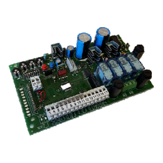
- Page 2 1. Introduction The control unit AS24 is particularly indicated for the installation of 1 or 2 wing gates with motors with direct current 24V and a maximum absorption of 7A.The control unit allows a precise regulation of the thrust of the gates, of the velocity and sensitivity on slowing phase and of the velocity and sensitivity on the running phase.
- Page 3 4. Preliminary checks Before connecting the control panel to the power supply, check all wirings which have been carried out. In particular check that there are no damaged wires, short-circuits between wires and that all accessories are connected to the terminal board in the points shown on the diagram on the previous page.
- Page 4 6. Setting the wing stroke This procedure must ONLY be carried out by the installer and ONLY during the setting up of the system. If you do not utilize any transmitter, it is necessary to use the Red key (P1) and BLUE (P2) present on the card or with P.P and PED buttons. Then you must carry out the following procedure: Close the door, see point 4, to move the wings manually.
- Page 5 8. Adjusting threshold of the ampere sensor in slowing down This procedure must ONLY be carried out by the installer and ONLY during the put in function of the system. For a correct programming, before carrying out any modification, bring always back the door to the totally closed position. SLOW.DOWN.
- Page 6 10. Adjusting of the motors velocity in slowing down This procedure must ONLY be carried out by the installer and ONLY during the put in function of the system. For a correct programming, before carrying out any modification, bring always back the door to the totally closed position. SLOW.DOWN.
- Page 7 12. Personalization of pedestrian opening This procedure must ONLY be carried out by the installer and ONLY during the put in function of the system. For a correct programming, before carrying out any modification, bring always back the door to the totally close position. If not personalized, pedestrian opening corresponds to the total opening of first wing.
- Page 8 14.8 Wings number setting The control unit AS24 can work with 1 or 2 wing gates. This setting is carried out putting the dip n° 8 on OFF if you want a 2 wing functioning and on ON if you want a single wing functioning. This setting MUST be carried out before the learning of the strokes.
- Page 9 15. Modality of photocells intervention The modality of photocells intervention is different: • The internal photocells unlock the movement until the obstacle is removed, so they involve the complete opening of the gate. • The external photocells do not intervene in opening, while they immediately invert the motion until the complete re opening in case of ob- stacle in closing.
- Page 10 19. Additional card (not supplied as standard) The control unit AS24 has a connector (see diagram on page 1) where it is possible to insert an additional card in order to have the outputs for connection of the electric lock and the courtesy light. The lighting time of the courtesy light is fixed at 1 minute and 30 seconds. It lights for every operation of the user.
Need help?
Do you have a question about the AS24 and is the answer not in the manual?
Questions and answers