
Related Manuals for Festo Checkbox Compact CHB-C-X


Summary of Contents for Festo Checkbox Compact CHB-C-X
- Page 1 Checkbox Compact Manual Checkbox Compact Type CHB-C-X Manual 533412 en 1102d [757659]...
- Page 2 Festo Checkbox ® is a registered trademark of Festo AG & Co. KG, D-73726 Esslingen, Germany...
- Page 3 ........533412 E (Festo AG & Co. KG, D-73726 Esslingen, Germany, 2011) Internet: http://www.festo.com E-mail: service_international@festo.com...
- Page 4 Contents and general instructions Festo P.BE-CB-COMP-EN en 1102d...
-
Page 5: Table Of Contents
..........2-20 Festo P.BE-CB-COMP-EN en 1102d... - Page 6 ..........Festo P.BE-CB-COMP-EN en 1102d...
- Page 7 ............Festo P.BE-CB-COMP-EN en 1102d...
-
Page 8: Intended Use
Please observe the standards specified in the relevant chapters and comply with the regulations of the trade associ- ation and the German Technical Control Board (TÜV), the VDE conditions as well as the relevant national regulations. Festo P.BE-CB-COMP-EN en 1102d... - Page 9 • If the laser beam hits the eye, consciously close your eyes and move your head out of the beam. Work with laser devices is subject to accident prevention regulations. Users must be instructed on the risks of look- ing directly into the beam. Festo P.BE-CB-COMP-EN en 1102d...
-
Page 10: Operating Requirements
This manual is intended exclusively for technicians trained in control and automation technology who have experience in installing and commissioning electronic systems. Service Please consult your local Festo Service if you have any technical problems. Scope of delivery Checkbox Compact... -
Page 11: Important User Instructions
This means that failure to observe this instruction may result in damage to property. The following pictograms also mark passages in the text which warn about the incorrect handling of certain components. Electrostatically sensitive devices. Incorrect handling can result in damage to components. Festo P.BE-CB-COMP-EN en 1102d... - Page 12 Marks sections dealing with environmentally protective measures. Text markings Bullet points indicate activities that may be carried out in any order. 1. Figures denote activities which must be carried out in the numerical order specified. – Hyphens indicate general activities. Festo P.BE-CB-COMP-EN en 1102d...
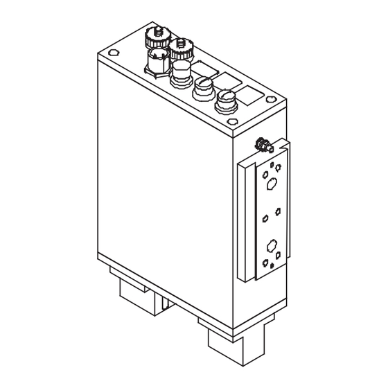
- Page 13 Input pin 1 Output pin 2 – Plug connectors are represented as when viewed on the device. This representation corresponds to the view of the (cable) connections which are to be wired. Festo P.BE-CB-COMP-EN en 1102d...
-
Page 14: Notes On The Use Of This Manual
Checkbox. Manuals on the software packages – Software CheckKon P.SW-KON – Operation of the CheckKon software – Software CheckOpti P.SW-OPTI – Operation of the CheckOpti software Tab. 0/1: Documentation on the Checkbox Festo P.BE-CB-COMP-EN en 1102d... -
Page 15: Product-Specific Terms And Abbreviations
0.25 s), or to look repeatedly into the laser beam or mirror-reflected laser beam. Class 3B Lasers of class 3B can produce serious eye damage. Longer radiation of a class 3B laser onto the skin causes erythema formation (reddened skin), pigmenting, burns or photochemical damage. XIII Festo P.BE-CB-COMP-EN en 1102d... - Page 16 This is also referred to as “Testing parts”. Tolerance Factor in per cent related to the average values and which affects the min./max. limits of all features. Tab. 0/2: Terms and abbreviations Festo P.BE-CB-COMP-EN en 1102d...
- Page 17 Contents and general instructions Festo P.BE-CB-COMP-EN en 1102d...
-
Page 18: System Summary
System summary System summary Chapter 1 Festo P.BE-CB-COMP-EN en 1102d... - Page 19 ........... . Festo P.BE-CB-COMP-EN en 1102d...
-
Page 20: The Festo Checkbox
1. System summary The Festo Checkbox ® The Festo Checkbox enables the optical (contactless) positioning and quality inspection of conveyed parts. Festo P.BE-CB-COMP-EN en 1102d... -
Page 21: Software Packages For The Checkbox
Tab. 1/1: Software package The CheckKon software package, operating system updates and current product information on the Checkbox Compact can be found in the Festo Internet pages under the address www.festo.com in the area “Support / Downloads”. Festo P.BE-CB-COMP-EN en 1102d... -
Page 22: Functional Range
= 1”, “External signal input activated= no”. Factory setting, can be set with CheckKon Extended quality inspection with CheckOpti (as from version 2.1) The system parameters must be activated or set in CheckKon Tab. 1/2: Functional range Festo P.BE-CB-COMP-EN en 1102d... -
Page 23: Operating Principle
Further transfer of good parts to a buffer zone or the next machine Sorting out bad parts (faulty parts, foreign parts) Return of incorrectly oriented parts to the small parts conveyor Fig. 1/1: Integrating the Checkbox in a conveyor device Example with conveyor belt and two actuators Festo P.BE-CB-COMP-EN en 1102d... - Page 24 (= scan) in the nominal orientation. 2. You scan the sample parts in further orientations if required. 3. You save the features of the parts type as Teach data. 4. You test the Teach data in the test mode. Festo P.BE-CB-COMP-EN en 1102d...
- Page 25 3 conveying paths: – Good parts are passed on e.g. to an assembly system. – Incorrectly oriented parts are returned to the small parts conveyor. – Faulty or foreign parts (bad parts) are rejected. Festo P.BE-CB-COMP-EN en 1102d...
-
Page 26: Buffer Zone
Planning the size of the buffer zone The buffer zone sections (see Fig. 1/2) must be dimensioned so that uninterrupted operation of the machine is possible. Instructions on dimensioning the buffer zone can be found in the following table. Festo P.BE-CB-COMP-EN en 1102d... - Page 27 The longer the section is, the less the switching frequency. Set the “Number of buffer zone sensors = 2” with CheckKon Tab. 1/3: Buffer zone sections Also observe Chapter 3.3 and Chapter 3.6.6 when connecting the buffer zone sensors. 1-10 Festo P.BE-CB-COMP-EN en 1102d...
- Page 28 1. System summary Transporting device Sensor 1 Fig. 1/2: Buffer zone check Transporting device Sensor 2 Sensor 1 Fig. 1/3: Buffer zone check with hysteresis 1-11 Festo P.BE-CB-COMP-EN en 1102d...
- Page 29 1. System summary 1-12 Festo P.BE-CB-COMP-EN en 1102d...
-
Page 30: Fitting And Commissioning
Fitting and commissioning Fitting and commissioning Chapter 2 Festo P.BE-CB-COMP-EN en 1102d... - Page 31 ..........2-20 Festo P.BE-CB-COMP-EN en 1102d...
-
Page 32: General Instructions
• Mount the Checkbox so that it is not possible to look directly into the laser beam. • Observe the warnings on the Checkbox. Warning Prism support Opening Fig. 2/1: Laser irradiation Festo P.BE-CB-COMP-EN en 1102d... -
Page 33: Mounting
Note the space required for mounting the Checkbox. The dimensions of the Checkbox and specifications on weight can be found in the Appendix A.5. Fastening On the side of the Checkbox there is a mounting profile with dovetail guide. Festo P.BE-CB-COMP-EN en 1102d... - Page 34 – the Checkbox and the conveyor device are fastened stably to each other (Fig. 2/3) – the viewing range of the camera is not impeded – the optical channel is not covered by the conveyor device. Festo P.BE-CB-COMP-EN en 1102d...
- Page 35 • Mount the Checkbox so that passing parts do not touch the glass surfaces. • Ensure the stable position of the parts, e.g. by means of mechanical devices. • If necessary, clean the glass surfaces, as described in Chapter 6 . Festo P.BE-CB-COMP-EN en 1102d...
-
Page 36: Electrical Connection
– 24 V power output for controlling the supply system (small parts conveyor) and the transporting system (conveyor device) – I/O signals for process monitoring and higher-order control or for controlling a downstream-switched machine. Festo P.BE-CB-COMP-EN en 1102d... - Page 37 EMERGENCY STOP (e.g. switching off the operating voltage, switching off pressure). Preparing plugs and cables Use plugs and sockets from the Festo supply programme which match the outer diameter of the cables used (www.festo.com/catalogue). Note...
- Page 38 Caution Long I/O signal lines reduce the resistance to interference. • Comply with the maximum permissible I/O signal line length of 30 m. Festo P.BE-CB-COMP-EN en 1102d...
-
Page 39: Selection Of The Power Supply Unit
Warning • Use only power sources which guarantee reliable electrical isolation of the operating voltage as per IEC/EN 60204-1. Observe also the general requirements for PELV power circuits as per IEC/EN 60204-1. 2-10 Festo P.BE-CB-COMP-EN en 1102d... -
Page 40: Connection Of The Operating Voltage
Use only a 4-pin M18 socket for the power supply and connect this only to the connection for the power supply. 1. Connect the plug to the 24 V DC connection on the Checkbox. 2. Tighten the union nuts of the plug by hand. 2-11 Festo P.BE-CB-COMP-EN en 1102d... -
Page 41: Power Supply For External Components
Make sure that the currents of the inputs and outputs flow via the Checkbox and not directly to the power unit. Consuming devices can also be supplied with voltage via the PLC plug. Observe also the information in Chapter 3.6. 2-12 Festo P.BE-CB-COMP-EN en 1102d... -
Page 42: Adapting System Parameters With Checkkon
In this way you can prevent parts from passing the actuator positions unchecked. 1. Adapt the Checkbox to your system requirements with the system parameters in the menu [Window] [System parameters]. Note also the instructions in the following chapters and in the software manual. 2-13 Festo P.BE-CB-COMP-EN en 1102d... - Page 43 3. Conclude CheckKon and with it the diagnostic mode when all settings have been completed. Note Faulty processing data can cause incorrect functioning of the Checkbox. • Carry out the complete Teach procedure again if you have modified the system parameters with CheckKon. 2-14 Festo P.BE-CB-COMP-EN en 1102d...
-
Page 44: Commissioning The Checkbox
– Switch between AUTO and TEACH modes – Selecting the orientation in the TEACH mode – Displaying the scan procedure – Accessing system information (e.g. belt speed during operation with encoder) – System information and operating displays 2-15 Festo P.BE-CB-COMP-EN en 1102d... - Page 45 In order to prevent the conveyor device from starting auto- matically when the operating voltage is switched on: • Select in CheckKon [Window] [System parameters] Z System Z Operating modes ... Z Automatic start after power supply on = no (factory setting). 2-16 Festo P.BE-CB-COMP-EN en 1102d...
- Page 46 Ready to operate (AUTO mode: stop status) For evaluation of the encoder signals, the operating system version ...E must be used. Consult your Festo Service if you wish to modify your operating system. Tab. 2/4: Operating display when switched on If “Lock”...
- Page 47 2. Press STATUS/TEACH button. Scan sample parts in the next orientation (2). 1 o2 Repeat the procedure for further orientations. 3. Press START/STOP button. Stop The Teach data will be saved and the TEACH mode will be concluded. 2-18 Festo P.BE-CB-COMP-EN en 1102d...
- Page 48 4. Conclude CheckKon when all the settings have been com- pleted. Switching off Switch the Checkbox to the Stop status before switching it off. Stop 1. Press START/STOP button. 2. Switch off the operating voltage. 2-19 Festo P.BE-CB-COMP-EN en 1102d...
-
Page 49: Error Diagnostics
40 ... 43 Data fault Teach data, configuration data or system parameters are not compatible or do not exist >=60 Hardware Internal fault (can only be eliminated fault by customer support) Tab. 2/6: Types of faults (overview) 2-20 Festo P.BE-CB-COMP-EN en 1102d... - Page 50 Details on the fault codes and instructions on eliminating faults can be found in Appendix A.1. – The CHB-C-X signals faults also at the PLC connection via O/17 (fault) and O/23 (warning) (see Chapter 3.6.7). 2-21 Festo P.BE-CB-COMP-EN en 1102d...
- Page 51 2. Fitting and commissioning 2-22 Festo P.BE-CB-COMP-EN en 1102d...
-
Page 52: The I/O Module
The I/O module The I/O module Chapter 3 Festo P.BE-CB-COMP-EN en 1102d... - Page 53 Locking the control panel ....... . . 3-31 Festo P.BE-CB-COMP-EN en 1102d...
-
Page 54: The I/O Module
– 24 V power output for controlling the supply system (small parts conveyor) and the transporting system (conveyor device) – I/O signals for process monitoring and higher-order control or for controlling a downstream-switched machine. Festo P.BE-CB-COMP-EN en 1102d... - Page 55 2.1 A BUFFER 1.4 A – Positive switching . 30 mA – Input current: Inputs , 15 V – Logical “1”: V . 5 V – Logical “0”: V Tab. 3/1: Electrical properties of the I/O signals Festo P.BE-CB-COMP-EN en 1102d...
-
Page 56: Actuators
Input I/19 on the PLC plug is intended for monitoring the pneumatic supply to the actuators. In the event of a fault this input will switch the Checkbox to error status E 01 by means of a pressure switch. Festo P.BE-CB-COMP-EN en 1102d... - Page 57 There is a +24 V DC signal when the inspection part passes the actuator position for good parts (here: the end of the transporting device). The duration of the signal corresponds to the time required for the part to reach the air jet nozzle. Festo P.BE-CB-COMP-EN en 1102d...
-
Page 58: Buffer/Feeder
(small parts conveyor) Reference voltage for sensors Buffer Buffer zone sensor 1 Do not connect Direct connection can optionally be made with a Festo Duo cable (see Accessories, Appendix A.6). Identifying the Duo cable Signal x Buffer zone sensor 1... - Page 59 (negative switching) in the rest state. Modification of the sensor type with CheckKon in the menu [Window] [System parameters]: Z System Z Transporting systems Z Continuing systems ... z Buffer zone sensor types = positive switching. Festo P.BE-CB-COMP-EN en 1102d...
- Page 60 Factory presetting; negative switching (NPN), 24 V DC active high To be set with CheckKon (recommendation); positive switching (PNP), 24 V DC active low Information on dimensioning the buffer zone can be found in Chapter 1.5. Festo P.BE-CB-COMP-EN en 1102d...
-
Page 61: Diag
2. Start CheckKon or CheckOpti in order to display the system data and to set the system parameters in the Teach or test modes. 3. Conclude CheckKon and CheckOpti when you have undertaken the necessary settings. 3-10 Festo P.BE-CB-COMP-EN en 1102d... - Page 62 Seal the connection with the protective cap supplied. Further information on commissioning, optimizing and monitoring the Checkbox via the diagnostic interface can be found in the documentation for the CheckKon and CheckOpti software packages. 3-11 Festo P.BE-CB-COMP-EN en 1102d...
-
Page 63: Encoder
Observe the following when connecting a rotary pulse generator: • Do not connect the potentials of the ENCODER connec- tion with other potentials. • Use only suitable rotary pulse generators, e.g. encoders from the Festo product range. 3-12 Festo P.BE-CB-COMP-EN en 1102d... - Page 64 Switching on). Note • Use the operating system version ...E to evaluate the encoder signals. • Consult your Festo Service if you wish to modify your operating system. Display of the belt speed Press the button STATUS/TEACH in AUTO mode.
-
Page 65: Plc
CHB-C-X. In this way you can prevent asymmetries of the currents in the outgoing and return lines from reducing the effect of the filter. Load output O/7 with maximum 700 mA. 3-14 Festo P.BE-CB-COMP-EN en 1102d... - Page 66 Fault status 1: Status signal “Fault” O/17 User-specific function. Consult your Festo Service if you have any problems. Counter function and special function “External sensor” cannot be used at the same time. Tab. 3/4: I/O functions of the PLC interface 3-15 Festo P.BE-CB-COMP-EN en 1102d...
- Page 67 . 5 V – Logical “0”: V Outputs: – Max. current loading per channel: 700 mA – Max. sum current of all outputs: 1 A – PNP switching Tab. 3/6: Electrical properties of the PLC interface 3-16 Festo P.BE-CB-COMP-EN en 1102d...
-
Page 68: Start/Stop Mode
With varying manual operation or control via the I/O module, pressing the START/STOP button corresponds to the signal change LOW > HIGH > LOW. The modification of the operating status with Start or Stop is sent to the controller via O/21. 3-17 Festo P.BE-CB-COMP-EN en 1102d... - Page 69 0.2 s . t rs . 1 s rs = remote start = min 0.1 s ts = type select = duration of the switch-on delay d = delay Tab. 3/8: Pulse-time diagram: Timing requirement to the higher-order controller 3-18 Festo P.BE-CB-COMP-EN en 1102d...
-
Page 70: Controlling The Teach Procedure
STATUS/TEACH. Customer-specific function Input I/15 is assigned with this function only at the customer’s wish. Consult your Festo Service if you have any problems. With the signal sequence LOW > HIGH > LOW at pin I/15 the CHB-C-X is switched to the TEACH mode. In order to teach the next orientation, a pulse must be given again via this in- put. - Page 71 Parts type change 1 > 4 Type 1 Type 4 Pin I/20 Type select 0 Pin I/5 Type select 1 Pin I/6 Remote start min 0.1 s Tab. 3/11: Pulse-time diagram: Parts type change 1 } 4 3-20 Festo P.BE-CB-COMP-EN en 1102d...
- Page 72 Number of buffer zone sensors = 1 Ext. type Ext. type Ext. type Ext. type z External signal input activated = no selection selection selection selection bit 0 bit 1 bit 2 bit 3 Tab. 3/12: Maximum number of parts types 3-21 Festo P.BE-CB-COMP-EN en 1102d...
- Page 73 HIGH HIGH HIGH HIGH 13 (display: “d”) 14 (display: “e”) HIGH HIGH HIGH 15 (display: “f”) HIGH HIGH HIGH 16 (display: “g”) HIGH HIGH HIGH HIGH Tab. 3/13: Binary coding parts type 1 ... 16 3-22 Festo P.BE-CB-COMP-EN en 1102d...
-
Page 74: Counting Function
• When the CHB-C-X is switched off, remove all good parts from the parts output. You will then avoid incorrect num- bers of items when the CHB-C-X is switched on again. 3-23 Festo P.BE-CB-COMP-EN en 1102d... - Page 75 Signal level Significance OW > HIGH > LOW I/18 Starts new counting cycle O/22 HIGH Preselected counter status reached Preselected counter status not yet reached Tab. 3/14: Signal sequence for controlling the counting pro- cedure 3-24 Festo P.BE-CB-COMP-EN en 1102d...
- Page 76 Control of counting Start Pin I/18 Start new counting cycle , 15 ms Pin O/22 Preselected counter status reached 10 ms sc = start counting cycle r = reset Tab. 3/15: Pulse-time diagram: Controlling the counting procedure 3-25 Festo P.BE-CB-COMP-EN en 1102d...
-
Page 77: Actuators
With a high pulse rate of the test parts, parts can be returned although other parts which have already been tested are not yet delivered. This delay arises due to the (long) distance between the actuator positions. 3-26 Festo P.BE-CB-COMP-EN en 1102d... -
Page 78: Buffer Zone Sensors/Small Parts Conveyor
This results in a delay of a few seconds between the external Start command (I/6) and the switch-on signal for the small parts conveyor (O/8). The duration of this delay depends on ambient parameters, e.g. transporting speed and geometrical variables. 3-27 Festo P.BE-CB-COMP-EN en 1102d... -
Page 79: Buffer Zone Sensors/Small Parts Conveyor
Z Continuing systems z Number of buffer zone sensors = 1 (2). The maximum number of parts types is reduced to 4 with the setting “Number of buffer zone sensors = 2” (See Chapter 3.6.3). 3-28 Festo P.BE-CB-COMP-EN en 1102d... - Page 80 To be set with CheckKon (recommendation); positive switching (PNP), 24 V DC active low with buffer zone monitoring – with one sensor: Sensor 1 Sensor 2 – with two sensors: Tab. 3/19: Sensor function for type NPN or PNP 3-29 Festo P.BE-CB-COMP-EN en 1102d...
-
Page 81: Fault Messages
By means of factory configuration or subsequent conversion in the CheckKon menu [Window] [System parameters], fault E 05 “No supply parts” can be defined as a warning F 05: Z System Z Fault treatment z Error/Warning 5 = Warning (see following table). 3-30 Festo P.BE-CB-COMP-EN en 1102d... -
Page 82: Locking The Control Panel
Tab. 3/23: Signal level: Locking the control panel Display Significance Lock Locking the control panel – Continuous display in Stop status – Display (duration 1.5 s) when the START/STOP button is pressed. Tab. 3/24: Display: Locking the control panel 3-31 Festo P.BE-CB-COMP-EN en 1102d... - Page 83 Acknowledge the message with the START/STOP button. The STATUS/TEACH button remains blocked until the function is switched off again in the menu [Window] [System parameters]: Z System Z Operating modes z Blocking the Teach button = off. 3-32 Festo P.BE-CB-COMP-EN en 1102d...
-
Page 84: Teaching Parts
Teaching parts Teaching parts Chapter 4 Festo P.BE-CB-COMP-EN en 1102d... - Page 85 ......4.2.2 Observing the scatter of characteristics ..... 4-10 Festo P.BE-CB-COMP-EN en 1102d...
-
Page 86: Teaching Parts
As standard during the Teach procedure, the parts are sorted out at the first actuator position. This is to ensure that no sample parts are transported by mistake to the next machine in the process. Festo P.BE-CB-COMP-EN en 1102d... - Page 87 During the trans- mission time no parts are checked. • Do not operate the Checkbox in diagnostic mode with the full parts rate. In this way you can prevent parts from passing the actu- ator positions unchecked. Festo P.BE-CB-COMP-EN en 1102d...
-
Page 88: The Teach Procedure
• Press the button START/STOP, in order to switch the Stop Checkbox into the Stop status. Scan sample parts of the parts type one after the other in all intended orientations (max. 8), as described below. Festo P.BE-CB-COMP-EN en 1102d... - Page 89 Repeat the procedure until the C-value remains almost constant. If a part has been incorrectly positioned (C-value changes erratically): Press the button START/STOP, in order to conclude the Teach procedure. Repeat the complete Teach procedure of the parts type. Festo P.BE-CB-COMP-EN en 1102d...
- Page 90 With the CheckOpti software even minimum differences in the features can be recognized. Further information can be ob- tained from your technical advisor. 5. Scan the sample parts of parts type 1 in orientation 2 1 o2 (o2) as described in point 2. Festo P.BE-CB-COMP-EN en 1102d...
- Page 91 Chapter 5. Keep a record of your work. Register the next parts type in a further Teach procedure: Address the next parts type via the PLC inputs (Chapter 3.6.3). Repeat all steps as from point 1. Festo P.BE-CB-COMP-EN en 1102d...
-
Page 92: Positioning The Sample Parts
Checkbox has recorded all intended orientations. For reliable testing, the ascertained features of the individual orientations must be clearly distinguished. Make sure in particular that orientation 1 (target orienta- tion) differs clearly in at least one feature from all the other orientations. Festo P.BE-CB-COMP-EN en 1102d... -
Page 93: Observing The Scatter Of Characteristics
Sample parts are very similar in all features , 30 Large scatter of at least one feature An exact description of the calculation algorithm for the scatter of characteristics can be found in Appendix A.3.2. Tab. 4/1: C-value (scatter of characteristics) 4-10 Festo P.BE-CB-COMP-EN en 1102d... -
Page 94: Testing Parts
Testing parts Testing parts Chapter 5 Festo P.BE-CB-COMP-EN en 1102d... - Page 95 Checking the orientation ........5-10 Festo P.BE-CB-COMP-EN en 1102d...
-
Page 96: Testing Parts
Protect the Teach data against undesired modification: – through control panel protection (see Chapter 3.6.8) – with the CheckKon software: [Window] [System parameters] Z System Z Operating modes ... z Teach button lock = On. Festo P.BE-CB-COMP-EN en 1102d... -
Page 97: Test Mode
(see Chapter 2.6 and Appendix A.1.2). 4. Check the test results e.g. with regard to the following aspects: Have the orientations been recognized correctly? Is the grading of the parts recognized as good/bad correct? Festo P.BE-CB-COMP-EN en 1102d... - Page 98 If the quality check and position recognition for the parts assortment are not satisfactory, you can use additional operating parameters and tools with CheckOpti in order to optimize the test results. Please consult your technical advisor. Festo P.BE-CB-COMP-EN en 1102d...
- Page 99 8. Press the button START/STOP, in order to switch the Checkbox into the Stop status. 9. Conclude the diagnostic mode. Close CheckKon (and CheckOpti). 10. Remove the diagnostic cable from the DIAG connection and seal the connection with the protective cap supplied. Festo P.BE-CB-COMP-EN en 1102d...
-
Page 100: Influence Of Tolerance
Standard setting Recommendation at least 1 % Stop 3. Release the START/STOP button when the desired value has been set. The value selected will be added automatically to the data of the parts type and saved. Festo P.BE-CB-COMP-EN en 1102d... - Page 101 Vary the tolerance so that the following test part devi- ation is shown when the limit sample part is scanned: ‹ 100 limit sample part “Good” › 100 limit sample part “Bad” Festo P.BE-CB-COMP-EN en 1102d...
-
Page 102: Evaluation Of The Test Results
Reject part The larger the value, the less the inspection part corresponds to the sample parts. Indicating range: 0 to 999 Tab. 5/1: Inspection part deviation Festo P.BE-CB-COMP-EN en 1102d... -
Page 103: Checking The Orientation
Inspection part The larger the value, orientation cannot be the less reliably the assigned clearly inspection part orientation will be recognized. Indicating range: 0 to 999 Tab. 5/2: Uncertainty of orientation recognition 5-10 Festo P.BE-CB-COMP-EN en 1102d... - Page 104 Maintenance Maintenance Chapter 6 Festo P.BE-CB-COMP-EN en 1102d...
- Page 105 ..........Festo P.BE-CB-COMP-EN en 1102d...
- Page 106 Note Damage to the glass surfaces can result in operative mal- functions of the Checkbox. • Consult your Festo Service in case of damage. The Checkbox has been designed for rough industrial environments and is distinguished by its high reliability, robust structure and long service life.
- Page 107 • with clean non-lubricated compressed air • with a soft moist cloth and non-abrasive cleaning agents. You will then avoid damage which could lead to malfunc- tioning of the Checkbox. Festo P.BE-CB-COMP-EN en 1102d...
- Page 108 Technical appendix Technical appendix Appendix A Festo P.BE-CB-COMP-EN en 1102d...
- Page 109 ........... . A-25 Festo P.BE-CB-COMP-EN en 1102d...
-
Page 110: Technical Appendix
– With CheckKon: switch from point/duration of the mode. the diagnostic mode to the Checkbox is not correct. operating mode, or – Inspection part deviation is – Conclude shown for an unusually long CheckKon/CheckOpti. time. Tab. A/1: Faults and remedies Festo P.BE-CB-COMP-EN en 1102d... -
Page 111: Fault Messages And Warnings
Note If fault messages and warnings are deactivated, undefined operating states and malfunctioning can occur in the event of a fault. Before deactivating, check whether additional measures are necessary for avoiding faults. Festo P.BE-CB-COMP-EN en 1102d... - Page 112 – If the glass surfaces are defective: Consult your Festo – Jam of parts in front of the Service. visual channel – Glass surface misted due to –...
- Page 113 E 10 I/O module 2. Check whether external outputs are loaded with an excessive current 3. Start the Checkbox or contact the Festo after-sales service. E 12 Overtemperature – Check ambient temperature – Prevent warmth from outside e.g. by sun shine.
- Page 114 E 41 The controller has lost the – With CheckKon: Load system parameters again system parameters – Contact the Festo after-sales service. E 42 The controller has lost the – With CheckKon: Load Teach data again configuration part of the teach –...
- Page 115 Moveable dirt particles on the – Clean the conveyor device number of bad parts has conveyor device. with compressed air. passed the test procedure. – Install a separator device in front of the conveyor device. Tab. A/3: Other fault states Festo P.BE-CB-COMP-EN en 1102d...
-
Page 116: Status Displays On The Control Panel
Number of memory modules for parts types and additionally the letter E with system setting “with encoder”. Example: 4 memory modules, encoder. 2048 System setting of the camera resolution Example: 2048 pixels Stop The Checkbox is in the Stop status Festo P.BE-CB-COMP-EN en 1102d... - Page 117 . 10: Sample parts are very similar in all features , 30: Large scatter of at least one feature tool Memory address assigned with measuring tool or optimized Teach data (CheckOpti) A-10 Festo P.BE-CB-COMP-EN en 1102d...
- Page 118 Preselected counter setting reached Display of the conveyor speed The operating system version ...E is required to display the conveyor speed [mm/s]. – Press the TEACH/STATUS button while the conveyor equipment is running. Tab. A/5: Display A-11 Festo P.BE-CB-COMP-EN en 1102d...
-
Page 119: Examples For Calculation Of The Features
B (C Average value of the feature Band width Feature maximum Upper limit of the band width incl. tolerance max tol Feature minimum Lower limit of the band width incl. Tolerance min tol Tolerance A-12 Festo P.BE-CB-COMP-EN en 1102d... - Page 120 Band width of the conveyed part length Band width at 5 % tolerance Result: All conveyed parts with a length of 57 … 68 mm are classified as good parts. The Checkbox ascertains appropriate value ranges for each feature. A-13 Festo P.BE-CB-COMP-EN en 1102d...
-
Page 121: Scatter Of Characteristics
“Length” of a conveyed part. The following values are taken from the example “Band width”: = 61.2 Average value of the length = 65 Length, maximum = 60 Length, minimum 65 60 100 % 61.2 8.2 % A-14 Festo P.BE-CB-COMP-EN en 1102d... -
Page 122: Inspection Part Deviation
The following values are taken from the example “Band width”: = 61.2 Average value of the length = 56.94 Length, lower limit min tol = 61 Length, current value actual 61 61.2 100 % 56.94 61.2 4.7 % A-15 Festo P.BE-CB-COMP-EN en 1102d... - Page 123 The following values are taken from the example “Band width”: = 61.2 Average value of the length = 68.06 Length, upper limit max tol = 64 Length, current value actual 64 61.2 100 % 68.06 61.2 40.8 % A-16 Festo P.BE-CB-COMP-EN en 1102d...
-
Page 124: Connections
Controlling the supply system (small parts conveyor) Reference voltage for sensors Buffer zone sensor 1 Do not connect Tab. A/7: BUFFER/FEEDER connector socket Direct connection can optionally be made with a Festo Duo cable (see Accessories, Appendix A.6.). A-17 Festo P.BE-CB-COMP-EN en 1102d... - Page 125 Actuator 3 Actuator 2 Actuator 1 Do not connect Tab. A/9: ACTUATORS connector socket Connector socket DIAG Received data Transmitted data Data GND Screened Interface for diagnostics PC: Cable type KDI-SB202-BU9 Tab. A/10: DIAG connector socket A-18 Festo P.BE-CB-COMP-EN en 1102d...
- Page 126 OUT24_Act2 Actuator 2 Green OUT24_Act3 Actuator 3 Yellow GND_NT 0 V / reference voltage for buffer zone sensors Grey IN24_TypeSel1 External type selection: Bit 1 Pink IN24_Ext_Start Save the Start/Stop mode and the Teach data A-19 Festo P.BE-CB-COMP-EN en 1102d...
- Page 127 Functions with a grey background have been deactivated at the factory and can be activated and adapted with CheckKon. The counting function and the special function “External sensor” cannot be used at the same time. User-specific function. Consult your Festo Service if you have any problems. Tab. A/12: PLC connector socket A-20...
- Page 128 24 V power output for controlling a small parts conveyor (feeder) 0 V reference voltage for buffer zone sensors Buffer zone sensor 1 I/12 ------ I/13 Buffer zone sensor 2 Tab. A/13: Internal circuitry of the connections A-21 Festo P.BE-CB-COMP-EN en 1102d...
-
Page 129: Technical Data
– Diagnostic interface RS 232 interface (115 kBaud), socket M12x1, 4-pin The device is intended for use in industrial environments. In residential areas, interference suppression measures might have to be taken. Tab. A/14: Technical data: General A-22 Festo P.BE-CB-COMP-EN en 1102d... - Page 130 Laser class 2 according to EN 60825-1:1994 + A1:2002 + A2:2001 (Class II according to CFR 21 §1040.10 USA). P ≤ 1 mW ë = 645 ... 665 nm Tab. A/17: Technical data: Camera and lighting A-23 Festo P.BE-CB-COMP-EN en 1102d...
- Page 131 Rotationally symmetrical parts and pre-oriented parts of any shape Min. part length 1 mm Max. part length Dependent on belt speed and required resolution Part diameter 0.5 ... 25 mm Tab. A/18: Technical data: Feature of conveyed parts A-24 Festo P.BE-CB-COMP-EN en 1102d...
-
Page 132: Accessories
A. Technical appendix Accessories Please select the appropriate accessories from our catalogue (www.festo.com/catalogue). A-25 Festo P.BE-CB-COMP-EN en 1102d... - Page 133 A. Technical appendix A-26 Festo P.BE-CB-COMP-EN en 1102d...
- Page 134 Index Index Appendix B Festo P.BE-CB-COMP-EN en 1102d...
-
Page 135: Index
............Festo P.BE-CB-COMP-EN en 1102d... - Page 136 ........Festo P.BE-CB-COMP-EN en 1102d...
- Page 137 ........3-16 Festo P.BE-CB-COMP-EN en 1102d...
- Page 138 ........3-31, A-10 Festo P.BE-CB-COMP-EN en 1102d...
- Page 139 ........Festo P.BE-CB-COMP-EN en 1102d...
- Page 140 ........Test procedure ......XIV, 1-8, 5-3 Festo P.BE-CB-COMP-EN en 1102d...
- Page 141 ........2-20, A-4 Festo P.BE-CB-COMP-EN en 1102d...
Need help?
Do you have a question about the Checkbox Compact CHB-C-X and is the answer not in the manual?
Questions and answers