
Related Manuals for Shure AXT400


Summary of Contents for Shure AXT400
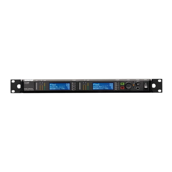
- Page 1 AXT400 Dual Channel Receiver Online user guide for AXT400 dual channel receiver. Version: 2 (2019-G)
-
Page 2: Table Of Contents
Shure Incorporated Table of Contents Automatic IP Addressing AXT400 Dual Channel Receiver Manual IP Addressing Troubleshooting IMPORTANT SAFETY INSTRUCTIONS Adding ShowLink for Remote Control AXT400 Dual Channel Receiver Interference Detection Features Detection Sensitivity Setting up an Audio Channel Included Components... -
Page 3: Axt400 Dual Channel Receiver
Shure Incorporated AXT400 Dual Channel Receiver IMPORTANT SAFETY INSTRUCTIONS READ these instructions. KEEP these instructions. HEED all warnings. FOLLOW all instructions. DO NOT use this apparatus near water. CLEAN ONLY with dry cloth. DO NOT block any ventilation openings. Allow sufficient distances for adequate ventilation and install in accordance with the manufacturer’s instructions. -
Page 4: Features
Interference Detection and Avoidance During operation, the AXT400 receiver can detect the presence of an interfering analog or digital signal. When a potential inter ference source is detected, a warning message is displayed along with options for changing frequency. When used with the AXT600 Spectrum Manager, the receiver can switch to a ‘backup’... -
Page 5: Included Components
The cascade ports share RF signal with up to 5 receivers within the same frequency band. RF cascade allows antenna signal to be conveniently distributed for up to 10 channels without using splitters or distribution amplifiers. Compatible Transmitters The receiver is compatible with the following Shure transmitters: • AXT100 Bodypack Transmitter •... -
Page 6: Front Panel
Shure Incorporated Front Panel ① Sync - Infrared (IR) Port Infrared (IR) port. For sending parameter presets (IR Preset) to a transmitter and linking the transmitter and receiver to the same channel. ② Squelch LEDs ◦ Blue (On) = transmitter signal detected ◦... -
Page 7: Rear Panel
Shure Incorporated ⑤ LCD display Each channel has an LCD display for viewing settings and parameters. ⑥ Menu navigation buttons Use to select and navigate through parameter menus. ⑦ Enter button The Enter button flashes when an action or parameter change is pending. Press Enter to save the value. - Page 8 Flashing = network link active, flash rate corresponds to traffic volume ⑦ Word clock input Connect to resolve the AXT400 AES3 digital output to an external word clock source. ⑧ Word clock thru output Passes word clock signal to additional components.
-
Page 9: Screen Icons
Displays the current level of the audio output (0 to -30 dB or Mute) In Talk Switch mode, the switch configuration is displayed: (TS-TRS, TS-XLR, TS-Toggle) Note: varies by region Displays the TV channel that contains the tuned frequency. Access Control Icon Displayed when Access Control PIN is enabled from Shure control software. 9/22... -
Page 10: Home Screen
Shure Incorporated Home Screen The home menu displays a summary of receiver parameters and the top-level menu choices. When a transmitter is received, its key settings are displayed. ① Audio channel name The audio channel name is shared by a receiver and a Linked transmitter ②... -
Page 11: Networking Receivers
The receiver uses an Ethernet connection to network with other components. For automatic network configuration, use a DHCP enabled Ethernet switch such as the Shure AXT620 or an Ethernet router with DHCP service. Use multiple Ethernet switches to extend the network for larger installations. -
Page 12: Troubleshooting
Start WWB6 software and use Inventory view to see devices connected to the network. If not, find the IP address from one of the devices on the network (such as an AXT400 receiver) and see if you can ping it from the computer running WWB6. -
Page 13: Interference Detection
Shure Incorporated ShowLink Test To check the ShowLink network and connectivity, you can use the ShowLink test mode in the AXT400 receiver: Connect the AXT610 Access Point to the network. Link a transmitter to the receiver by doing an IR sync. -
Page 14: Detection Sensitivity
Shure Incorporated On-Screen Frequency Change Options When Avoidance mode is set to Prompt, the following on-screen options are available when interference is detected: • Switch: Deploys a clear backup frequency from the Spectrum Manager when selected • Manual: Accesses the frequency menu to make a frequency change using the control wheel •... - Page 15 Shure Incorporated From the home menu screen, select Radio. Press the control wheel to highlight Band. Turn the control wheel to set the receiver band to match the transmitter band. Press the ENTER button to save. Linking a Transmitter using IR Sync The IR Sync function forms a link between a transmitter and the receiver and automatically sets the transmitter frequency.
-
Page 16: Frequency Diversity
To set Frequency Diversity mode: Menu: Options > Diversity Turn the control wheel to select FD-Bodypack for AXT100 bodypack transmitters or to select FD-Handheld for AXT200 handheld transmitters. Specifications Specifications AXT400 Receiver RF Carrier Frequency Range 470–952 MHz Note: varies by region Working Range... - Page 17 Shure Incorporated Signal-to-Noise Ratio A-weighted, 1% THD XLR Output >118 dB AES3 Output >130 dB Image Rejection >120 dB, typical RF Sensitivity -110 dBm for 12 dB SINAD, typical Spurious Rejection >110 dB, typical Ultimate Quieting >110 dB, A-Weighted Squelch Quieting >115 dB, A-Weighted...
- Page 18 Shure Incorporated Current Drain 1.1 A RMS (referenced at 120 V AC) Operating Temperature Range -18°C (0°F) to 63°C (145°F) Storage Temperature Range -29°C (-20°F) to 74°C (165°F) RF Input Connector Type Configuration Unbalanced, active Impedance 50 Ω Bias Voltage...
-
Page 19: Analog Audio Output
Shure Incorporated Pin Assignments ground audio + audio - Phantom Power Protection Networking Power Over Ethernet (PoE) 50 V DC, Class 1 Network Interface Dual Port Ethernet 10/100 Mbps Network Addressing Capability DHCP or Manual IP address Analog Audio Output Configuration Unbalanced mono, 1/4 in. -
Page 20: System Gain
The table below offers a comparison of the output gain at the XLR output for AXT400 and UR4 receivers for each transmitter model. Use the information in the table to achieve consistent gain levels when using systems comprised of both Axient series and UR series components. -
Page 21: Certifications
Changes or modifications not expressly approved by the manufacturer could void the user’s authority to operate the equipment. The CE Declaration of Conformity can be obtained from Shure Incorporated or any of its European representatives. For contact information please visit www.shure.com The CE Declaration of Conformity can be obtained from: www.shure.com/europe/compliance... - Page 22 Shure Incorporated mined by turning the equipment off and on, the user is encouraged to try to correct the interference by one or more of the fol lowing measures: • Reorient or relocate the receiving antenna. • Increase the separation between the equipment and the receiver.
Need help?
Do you have a question about the AXT400 and is the answer not in the manual?
Questions and answers