Advertisement
- 1 System Overview
- 2 Guitar Pedal Receiver
- 3 Display Screen, Indicators, and Controls
- 4 Bodypack Transmitter
- 5 Batteries and Charging
- 6 Tips to Improve Wireless System Performance
- 7 Receiver Operation
- 8 Tuner Menu
- 9 Using the Tuner
- 10 Using a Third-Party Power Supply
- 11 Firmware
- 12 Resetting Components
- 13 Troubleshooting
- 14 Accessories
- 15 Specifications
- 16 Frequency Tables
- 17 IMPORTANT SAFETY INSTRUCTIONS
- 18 Documents / Resources
System Overview
GLX-D+ Dual Band Digital Wireless offers confidence without complexity. Dual-band operation in 2.4 and 5.8 GHz more than doubles the available bandwidth to avoid interference without audio interruption. The receiver is compatible with a selection of lavalier, headset, and vocal microphones. The included lithium-ion battery offers up to 12 hours of runtime, and can be charged directly on the receiver or via USB-C.
Features
- Exceptional digital audio clarity
- Compatible with multiple legendary microphone options
- Automatically moves away from interference without audio interruption
- Operates in 2.4 and 5.8 GHz spectrum*
- Rechargeable battery delivers up to 12 hours of runtime
- Rock-solid RF performance for multiple system installations
- License-free frequency range
Note: region dependent
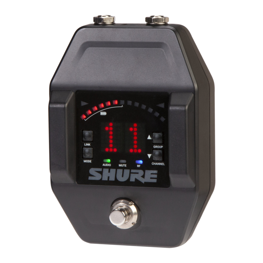
Guitar Pedal Receiver

| Connect DC power supply (9 to 15 V DC, 400 mA minimum). Note: Compatible with positive tip or negative tip power supplies. |
| Use receiver as a wired guitar pedal tuner. |
| Connect to amplifier or mixer. Note: If using multiple effects pedals, place the receiver pedal first in the signal chain. |
| Connect to computer to download firmware updates. |
| Shows receiver and tuner settings. See below for more information on display controls. |
| Two antennas per receiver. Antennas pick up the signal from the transmitter. |
| Press to select receiver or tuner mode. |
Display Screen, Indicators, and Controls
The controls and display offer specific functionality depending on which mode is selected:
Receiver Mode

| Illuminated segments indicate remaining battery life. |
| Group Channel LK (controls locked) UN (controls unlocked) -- (frequency not available) |
| Press to manually link receiver to a transmitter or to activate the remote ID function. |
| Press to enable audio gain adjustment. Use ▲ ▼ buttons to adjust gain. |
| Illumination corresponds to audio level. Rapid flashing indicates audio clipping. |
| Illuminates when audio output is muted. |
|
|
| Press to select and edit channel. |
| Press to select and edit group. |
Tuner Mode

| Illuminates when note is flat. |
| LEDs illuminate to indicate tuning deviation. |
| Illuminates when note is sharp. |
| Displays the name of the note or (--) if the tuner is idle. |
| Press to enter tuner menu settings. |
| Use ▲ ▼ buttons to select and edit menu settings. |
| A dot is displayed when the tuning or pitch has been set to a non-standard value. Note: Non-standard tuning or pitch settings scroll across the receiver display during power-up. |
Set Up the Receiver

- Connect the PS24 power supply to the receiver and plug the cord into an AC power source.
- Connect the transmitter to the instrument.
- Connect the audio output to an amplifier or mixer.
Note: The receiver powers on after the power supply and ¼" cable are connected.
Bodypack Transmitter

- Antenna
Carries wireless signal. - Status LED
LED color and state indicate transmitter status. - Power switch
Turns the transmitter on/off. - TA4M input port
Connects to a 4-Pin mini connector (TA4F) microphone or instrument cable. - USB-C charging port
Connect to USB battery charger. - Link button
- Press and hold within 5 seconds of power-on to manually link with receiver.
- Press momentarily to activate remote ID function.
- Battery compartment
Holds 1 Shure rechargeable battery.
Transmitter Status LED
LED is green during normal operation.
LED color or flashing indicates a change in transmitter status as shown in the following table:
| Color | State | Description |
| Green | Flashing (slow) | Transmitter attempting relink with receiver |
| Flashing (fast) | Unlinked transmitter searching for receiver | |
| Flashes 3 times | Indicates locked transmitter when power switch is pressed | |
| Red | On | Battery life < 1 hour |
| Flashing | Battery life < 30 minutes | |
| Red/Green | Flashing | Remote ID active |
| Amber | Flashing | Battery error; remove and insert again, or replace battery |
Wearing the Bodypack
Clip the bodypack to a belt or slide a guitar strap through the bodypack clip as shown.

For best results, the belt should be pressed against the base of the clip.
Install Transmitter Batteries

Always fully charge a new battery before first use.
- Move the locking lever to the open position and slide the battery door open.
![]()
- Place the battery into the transmitter.
- Close the battery door.

Batteries and Charging
GLX-D+ transmitters are powered by Shure SB904 lithium-ion rechargeable batteries. Advanced battery chemistry maximizes runtimes with zero memory effects, eliminating the need to discharge batteries prior to charging.
When not in use, recommended battery storage temperature is 10°C (50°F) to 25°C (77°F).
Note: The transmitter will not pass RF or audio signals when connected to the charging cable.
The following battery charging options are available:
Charging from an AC Power Source

- Plug the charging cable into the charging port on the transmitter.
- Plug the charging cable into an AC power source.
Charging Status LEDs
| LED Color | Description |
| Green (solid) | Device is fully charged |
| Red (solid) | Charging |
| Amber (flashing) | Out of temperature range, or battery error |
| Off | Power supply is disconnected, or no device is docked in the charging bay |
Charging Times and Transmitter Runtimes
Use the following table to determine approximate battery runtime based on the duration of charging time when in 5.8 GHz mode. Times shown are in hours and minutes. Transmitters automatically power off after approximately 1 hour to conserve battery life if the signal from a linked receiver is not detected.
| Receiver Bay or AC Power Source Charging | Transmitter Runtime |
| 0:15 | up to 1:30 |
| 0:30 | up to 3:00 |
| 1:00 | up to 6:00 |
| 3:00 | up to 11:30* |
Note: If receiver is powered off and remains plugged in, battery will continue charging.
Transmitter Battery Meter
The number of segments illuminated on the meter indicates the remaining battery life for a linked transmitter:

- = > 30 min
- = > 2 hours
- = > 4 hours
- = > 6 hours
- = > 8 hours
- = > 10 hours
- = > 11.5 hours
Note: The LEDs will cycle on/off while battery life is being calculated.
Important Tips for Care and Storage of Shure Rechargeable Batteries
Proper care and storage of Shure batteries results in reliable performance and ensures a long lifetime.
- Always store batteries and transmitters at room temperature
- Ideally, batteries should be charged to approximately 40% of capacity for long-term storage
- During storage, check batteries every 6 months and recharge to 40% of capacity as needed
Tips to Improve Wireless System Performance
If you encounter interference or dropouts, try the following suggestions:
- Frequency TablesPlace receiver at least 3 meters (10 feet) away from Wi-Fi access points, computers, or other active 2.4 GHz and 5.8 GHz sources.
- Avoid heavy Wi-Fi traffic activities such as downloading large files or viewing a movie.
- Turn on any Wi-Fi prior to turning on receivers and scanning for the best channel. MReduce transmitter-to-receiver distance by placing receivers on stage or above the audience with a clear line of sight to the transmitter.
- Move receiver to the top of the equipment rack for a clear line of sight.
- Mount antennas remotely to place closer to transmitters and improve RF reliability if receivers cannot be moved closer.
- Make sure people do not block the line of sight between receiver and transmitter.
Additional Tips
- Do not place competitive 2.4 GHz and 5.8 GHz receivers near GLXD4R+ receivers.
- Scan for the best available channel by pressing the channel button.
- Keep transmitters more than 2 meters (6 feet) apart. This is less critical with shorter receiver-to-transmitter distances.
Note: If transmitters are within 6 inches of non-GLX-D+ transmitters or microphone cartridges, audible noise is possible. - Move transmitter and receiver away from metal or other dense materials.
- During sound check, mark trouble spots and ask performers to avoid those areas.
Receiver Operation
Audio Gain Adjustment
Transmitter gain has an adjustment range from -20 dB to +40 dB in 1 dB increments.
Tip: Try the 0 dB (unity gain) setting as a starting point, and then make gain adjustments if necessary.
- Press and hold the mode button on the receiver until dB appears on the display.
![]()
- Press the up/down arrows to adjust the gain. For faster adjustments, press and hold the buttons.
![]()


Note: The intensity of the green audio LED corresponds to the audio level. Rapid flashing indicates audio clipping. Reduce the gain to remove the overload.
Locking and Unlocking the Controls
The controls of the receiver and transmitter can be locked to prevent unauthorized setting changes or power off. The lock status is not changed by power cycles.
Locking the Receiver Controls
Simultaneously press and hold the group and channel buttons until LK appears on the screen. Repeat to unlock.
- LK is displayed if a locked control is pressed
- UN is displayed momentarily to confirm the unlock command
Locking the Transmitter Controls
To lock directly from the transmitter:
Start with the transmitter off, then press and hold the link button while turning on the transmitter. Release the link button when the transmitter powers on to prevent an accidental factory reset. The lock icon appears on the receiver screen when locked. Repeat sequence to unlock.
To lock from the receiver front panel:
Simultaneously press and hold the group and link buttons for approximately 2 seconds until the flashing lock icon appears on the receiver screen. Repeat sequence to unlock.
Note: The transmitter status LED will flash if a locked switch is set to the off position.
Identifying Linked Transmitters and Receivers with Remote ID
Use the remote ID feature to identify linked transmitter and receiver pairs in multiple receiver systems.
To activate remote ID:
- Momentarily press the link button on the transmitter or receiver.
- The screen of the linked receiver will blink and display ID, while the status LED on the linked transmitter will flash red/ green.
- To exit remote ID mode, momentarily press the link button or allow the function to timeout.
Receiver Band Modes
There are 3 band modes available for GLXD+ receivers.* The band mode options are:
- 2.4 GHz-only mode
- 5.8 GHz-only mode
- Best band mode - 2.4 and 5.8 GHz (default)
Note: region dependent
To change the band mode:
- Press and hold the channel button while powering on the receiver. Continue to hold the channel button for approximately 5 seconds until the band selection menu opens.
- Press the up/down gain button to select a band mode. The screen will flash momentarily and scan for the best channel to use.
Note: Linked receivers and transmitters must be able to operate in the same band. Transmitters that don't support the selected band mode will unlink from the receiver.
Tuner Menu
Enter tuner mode by pressing the footswitch.
In tuner mode, the controls will only affect tuner functions. RF and audio settings are not affected.
Note:
- Wired use: Wired input does not load the guitar signal, eliminating the need for bypass switches. The unit passes wired signal if power is lost to the pedal.
- Wireless use: Bypass does not apply because the pedal needs to be powered on to receive wireless signal.
Tuner Options
- Indicator: Needle or Strobe
- Output: Live, Mute, Both, or A/B
- Display Brightness
- Detune
- Sharps and Flats
- Reference Pitch
Selecting and Editing Tuner Menu Settings
Use the following buttons to select and edit the tuner menu settings:
- Use the mode button to access the menu and scroll between menu settings.
- Use the ▲ ▼ buttons to change a menu parameter.
- Use the footswitch to enter and save parameter changes.
Indicator: Needle or Strobe
The tuner indicator can be set to display a needle style or strobe style.
Needle
A single LED will illuminate on the tuning bar to indicate sharp or flat. The green center LED will illuminate when the note is in tune.

Strobe
A sequence of three LEDs will travel across the tuning bar in the direction of sharp or flat. The LEDs will remain stationary when the note is in tune.

Note: Indicator and Output settings are displayed in a scroll from left to right.
Choosing Audio Output
Set the audio output to the following modes when the footswitch is pressed in tuner mode.
Note: Text for the output settings are displayed in a scroll from left to right.
| Mode | Footswitch Function |
| Live | Receiver Display (audio Live) ↔ Tuner Display (audio Live) |
| Mute | Receiver Display (audio Live) ↔ Tuner Display (audio Mute) |
| Both* | Tuner Display (audio Mute) ↔ Tuner Display (audio Live) |
| A/B** | Tuner Display (audio Live) ↔ Tuner Display (audio Live) |
* In Both mode, the pedal powers up in Receiver Display. Press the footswitch to enter tuner mode.
**In A/B mode, press the footswitch to easily switch between your transmitter (TX) and wired input (IN).
Display Brightness
The receiver has a built-in light sensor to automatically adjust the display brightness.

To manually adjust the brightness choose one of the following settings:
Detune
The tuner can be set to display standard tuning for instruments that have been detuned up sharp or flat in the following increments:

- Up to 5 steps sharp (#1-#2 -#3-#4-#5)
- Up to 6 steps flat (b6-b5-b4-b3-b2-b1)
The notation for standard tuning is b0
Note: A dot appears on the display as a reminder that the pedal is detuned.
Sharps and Flats
Adds sharp or flat symbols to the display of non-natural notes.

Reference Pitch
The reference pitch can be offset from standard A440 in a range of 432 Hz to 447 Hz in 1 Hz increments.
When adjusting the pitch, the last 2 digits of the value will be displayed. For example, "32" would appear on the display when the pitch has been set to 432 Hz.

A dot appears on the display as a reminder that the reference pitch has been offset.
Using the Tuner
- Press the footswitch to enter tuner mode.
- Play each note individually. The display shows the name of the note.
- Adjust tuning until both indicators illuminate and the needle or strobe indicate that tuning is correct.
Needle Mode
Both tuning indicators and the center green segment will illuminate when the note is in tune.

Strobe Mode
Both tuning indicators will illuminate and the strobe segments will remain stationary when the note is in tune.

Using a Third-Party Power Supply
To power your wireless receiver pedal, we recommend using the included power supply or a power supply with isolated power outputs.
If using a power supply with isolated power outputs, use a power outlet rated at a minimum of 400 mA.
However, if using other third-party power supplies:
- Check the power consumption for each pedal in a daisy-chain setup. You must know the total power consumption for all of your pedals to avoid overloading the power supply.
- If no power requirement is listed on the pedal, consult the pedal manufacturer.


Firmware
New versions of the firmware can be uploaded and installed using the Shure Update Utility tool.
Download Shure Update Utility from shure.com
To update your firmware, connect the device to your computer using a USB-C cable and open the Shure Update Utility.
Resetting Components
Use the reset function if it is necessary to restore the transmitter or receiver to their factory settings.
Resetting the Receiver
Restores the receiver to the following factory settings:
- Gain level = default
- Controls = unlocked
Press and hold the link button while turning on the receiver power until the display shows RE.
Note: When reset is complete, the receiver will automatically initiate linking to search for a transmitter. Press and hold the transmitter link button within five seconds of powering-on to complete the link.
Resetting the Transmitter
Restores the transmitter to the following factory settings:
- Controls = unlocked
Press and hold the transmitter link button while turning on the transmitter until power LED turns off.
When the link button is released, the transmitter will automatically initiate linking to find an available receiver. Press the link button on an available receiver to relink.
Troubleshooting
| Issue | Indicator Status | Solution |
| No sound or faint sound | Receiver RF LED on | Verify all sound system connections or ad just gain as needed. Verify that the receiver is connected to mix er/amplifier. |
| Receiver RF LED off | Turn on transmitter. Make sure the batteries are installed correct ly. Link transmitter and receiver. Charge or change transmitter battery. | |
| Receiver display off | Make sure AC adapter is securely plugged into electrical outlet. Make sure receiver is powered on. | |
| Transmitter indicator LED flashing red | Charge or change transmitter battery. | |
| Transmitter plugged into charger. | Disconnect transmitter from charger. | |
| Audio artifacts or dropouts | RF LED flickering or off | Change receiver and transmitter to a differ ent group and/or channel. Identify nearby sources of interference (cell phones, Wi Fi access points, signal proces sor, etc.) and shutdown or remove source. Charge or change transmitter battery. Ensure that receiver and transmitter are po sitioned within system parameters. System must be set up within recommended range and receiver kept away from metallic surfaces. Transmitter must be used in line of sight from receiver for optimal sound. |
| Distortion | OL indicator appears on receiver display | Reduce transmitter gain. |
| Transmitter and receiver link unsuccessful | Transmitter and receiver LEDs flash to indicate that linking started, but the link fails | Update both components to the latest firmware version. |
| Sound level variations when switching to dif ferent sources | N/A | Adjust transmitter gain as necessary. |
| Receiver/transmitter won't turn off | Transmitter LED flash ing rapidly | Controls locked. |
| Receiver gain control cannot be adjusted | N/A | Check transmitter. Transmitter must be on to enable gain changes. |
| Receiver controls cannot be adjusted | LK shown on receiver display when buttons are pressed | Controls locked. |
| Transmitter ID function does not respond | Transmitter LED flashes green 3 times | Controls locked. |
| Transmitter information does not appear on the receiver display | N/A | Linked transmitter is off or the receiver is not linked to a transmitter. |
| Transmitter powers off after 1 hour | Transmitter status LED off | Transmitters automatically power-off after 1 hour to conserve battery life if the signal from a linked receiver is not detected. Make |
Accessories
| Cable, Instrument, 2.5 foot (.75 m), 4 Pin Mini Connector (TA4F) to 1/4 inch Connec tor. | WA302 |
| Cable, Instrument, 2-foot (0.7m), 4-pin Mini Connector (TA4F) with Right-Angle 1/4- inch Connector, used with Shure Wireless Bodypack Transmitters | WA304 |
| Shure Rechargeable Battery | SB904 |
| USB-C Battery Charger | SBC10-USBC |
| Premium Guitar Cable TQG Threaded Connector | WA305 |
| Power Supply | PS24 |
Specifications
Tuning Bandwidth
| Z2 | 2400 - 2483.5 MHz |
| Z3 | 2400 - 2483.5 MHz and 5725 - 5850 MHz |
| Z4 | 2400 - 2483.5 MHz and 5725 - 5875 MHz |
| Z5 | 2400 - 2483.5 MHz and 5725 - 5825 MHz |
Dependent on frequency band
Transmit Mode
Shure proprietary digital
RF Output Power
10 mW E.I.R.P. maximum
Operating Temperature Range
0°C (32°F) to 50°C (122°F)
Polarity
Positive voltage applied to the tip of the guitar cable phone plug produces positive voltage at the tip of the high impedance ¼-inch output
Audio Frequency Response
20 Hz – 20 kHz
Dynamic Range
120 dB, A-weighted
RF Sensitivity
-88 dBm, typical
Total Harmonic Distortion
0.02%, typical
Battery Life
Up to 11.5 hours
Guitar Tuner
| Tuning Accuracy | ±1 cent |
| Tuning Range | F#0 to C8 |
Channel Count
Up to 4 typical, 8 optimal
2.4 GHz only: Up to 4 typical, 5 optimal
GLXD6+
Power Requirements
9 V – 15 V, 400 mA (efficiency level VI power supply)
Antenna Type
Dual-band PIFA
Dimensions
5.4 x 3.7 x 1.89 in. (138 x 95 x 48 mm)
Weight
19.75 oz (560 g)
Housing
Aluminum alloy
Spurious Rejection
> 35 dB, typical
Gain Adjustment Range
-20 to 40 dB in 1 dB steps
Audio Input Modes
Tuner or True Bypass
AUDIO OUTPUT
Configuration
6.35 mm (1/4") output
Impedance balanced
Impedance
6.35 mm (1/4") output
100 Ω (50 Ω, Unbalanced)
Maximum Audio Output Level
6.35 mm (1/4") connector (into 3 kΩ load)
+8.5 dBV
Pin Assignments
6.35 mm (1/4") connector
Tip=audio, Ring=no audio, Sleeve=ground
RECEIVER ANTENNA INPUT
Impedance
50 Ω
Maximum Input Level
-20 dBm
GLXD1+
Power Requirements
| Shure Rechargeable Li-Ion Battery | SB904 |
| USB Power Supply (US/Canada) | SBC10-USB15WSUSTWJ |
Antenna Typ
Dual-band Internal Monopole
Dimensions
4.5 x 2.6 x 1.1 in. (115 x 66.94 x 28.51 mm), (H x W x D)
Weight
5.4 oz (153.1 g), without battery
Housing
Aluminum alloy, ABS plastic
Input Impedance
900 kΩ
TX INPUT
Connector
4-pin male mini connector (TA4M)
Maximum Input Level
+8.4 dBV (7.5 Vp-p)
Configuration
Unbalanced
Pin Assignments
| 1 | Ground (cable shield) |
| 2 | + 5 V bias |
| 3 | Audio |
| 4 | Tied through active load to ground (on instru ment adapter cable, pin 4 floats) |
SB904
Battery Type
Rechargeable Li-Ion
Nominal Capacity
2420 mAh (8.71 Wh)
Nominal Voltage
3.6 V
Dimensions
2.87 x 0.83 x 0.82 inches (72.8 x 20.96 x 20.80 mm), (H x W x D)
Weight
1.89 oz. (53.7 g)
Housing
PC/ABS
Ambient Temperature Range
| Charging: | 0°C (32°F) to 40°C (104°F) |
| Operating: | 18°C (0°F) to 45°C (113°F) |
SBC10-904
DC Input Voltage
5 V
Ambient Temperature Range
Operating:
0°C (32°F) to 40°C (104°F)
SBC10-USB15W Power Supply
Input Voltage Range
100 to 240 V AC
Maximum Input Power
600 mA @ 100 V AC (full load)
Output Voltage
5 v DC @ 3 A
Maximum Output Power
15 W
SBC10-USB Power Supply
Input Voltage Range
100 to 240 V AC
Maximum Input Power
200 mA @ 100 V AC (full load)
Output Voltage
5 v DC @ 1 A
Maximum Output Power
5 W
Diagrams

Frequency Tables
Z2 (2.4 GHz only)
| Group 1 | ||||||
| Gr 1 - Ch 1 | 2424 | 2425 | 2442 | 2443 | 2462 | 2464 |
| Gr 1 - Ch 2 | 2418 | 2419 | 2448 | 2450 | 2469 | 2471 |
| Gr 1 - Ch 3 | 2411 | 2413 | 2430 | 2431 | 2476 | 2477 |
| Gr 1 - Ch 4 | 2405 | 2406 | 2436 | 2437 | 2455 | 2457 |
| Group 2 | ||||||
| Gr 2 - Ch 1 | 2423 | 2424 | 2443 | 2444 | 2473 | 2474 |
| Gr 2 - Ch 2 | 2404 | 2405 | 2426 | 2427 | 2456 | 2457 |
| Gr 2 - Ch 3 | 2410 | 2411 | 2431 | 2432 | 2448 | 2449 |
| Gr 2 - Ch 4 | 2417 | 2418 | 2451 | 2452 | 2468 | 2469 |
| Gr 2 - Ch 5 | 2437 | 2438 | 2462 | 2463 | 2477 | 2478 |
| Group 3 | |||
| Gr 3 - Ch 1 | 2415 | 2416 | 2443 |
| Gr 3 - Ch 2 | 2422 | 2423 | 2439 |
| Gr 3 - Ch 3 | 2426 | 2427 | 2457 |
| Gr 3 - Ch 4 | 2447 | 2448 | 2468 |
| Gr 3 - Ch 5 | 2409 | 2451 | 2452 |
| Gr 3 - Ch 6 | 2431 | 2462 | 2463 |
| Gr 3 - Ch 7 | 2404 | 2473 | 2474 |
| Gr 3 - Ch 8 | 2435 | 2477 | 2478 |
| Group 4 | |||||
| 2404 | 2406 | 2408 | 2410 | 2412 | 2414 |
| 2416 | 2418 | 2420 | 2422 | 2424 | 2426 |
| 2428 | 2430 | 2432 | 2434 | 2436 | 2438 |
| 2440 | 2442 | 2444 | 2446 | 2448 | 2450 |
| 2452 | 2454 | 2456 | 2458 | 2460 | 2462 |
| 2464 | 2466 | 2468 | 2470 | 2472 | 2474 |
| 2476 | 2478 | ||||
Z3
| Group 1 (2.4 GHz) | ||||
| Gr 1 - Ch 1 | 2405 | 2323 | 2441 | 2465 |
| Gr 1 - Ch 2 | 2411 | 2429 | 2447 | 2471 |
| Gr 1 - Ch 3 | 2417 | 2435 | 2453 | 2477 |
| Group 2 (2.4 GHz) | ||||
| Gr 2 - Ch 1 | 2404 | 2424 | 2444 | 2464 |
| Gr 2 - Ch 2 | 2409 | 2429 | 2449 | 2469 |
| Gr 2 - Ch 3 | 2414 | 2434 | 2454 | 2474 |
| Gr 2 - Ch 4 | 2419 | 2439 | 2459 | 2478 |
| Group 3 - Channel 1 (2.4 GHz) | |||||
| 2405 | 2408 | 2411 | 2414 | 2417 | 2420 |
| 2423 | 2426 | 2429 | 2432 | 2435 | 2438 |
| 2441 | 2444 | 2447 | 2450 | 2453 | 2456 |
| 2459 | 2462 | 2465 | 2468 | 2471 | 2474 |
| 2477 | |||||
| Group 1 (5.8 GHz) | ||||
| Gr 1 - Ch A | 5730 | 5760 | 5790 | 5820 |
| Gr 1 - Ch B | 5736 | 5766 | 5796 | 5826 |
| Gr 1 - Ch C | 5742 | 5772 | 5802 | 5832 |
| Gr 1 - Ch D | 5748 | 5778 | 5808 | 5838 |
| Gr 1 - Ch E | 5754 | 5784 | 5814 | 5845 |
| Group 2 (5.8 GHz) | ||||
| Gr 2 - Ch A | 5729 | 5759 | 5789 | 5819 |
| Gr 2 - Ch B | 5734 | 5764 | 5794 | 5824 |
| Gr 2 - Ch C | 5739 | 5769 | 5799 | 5829 |
| Gr 2 - Ch D | 5744 | 5774 | 5804 | 5836 |
| Gr 2 - Ch E | 5749 | 5779 | 5809 | 5841 |
| Gr 2 - Ch F | 5754 | 5784 | 5814 | 5846 |
| Group 3 - Channel A (5.8 GHz) | |||||
| 5730 | 5733 | 5736 | 5739 | 5742 | 5745 |
| 5748 | 5751 | 5754 | 5757 | 5760 | 5763 |
| 5766 | 5769 | 5772 | 5775 | 5778 | 5781 |
| 5784 | 5787 | 5790 | 5793 | 5796 | 5799 |
| 5802 | 5805 | 5808 | 5811 | 5814 | 5817 |
| 5820 | 5823 | 5826 | 5829 | 5832 | 5835 |
| 5838 | 5841 | 5845 | |||
Z4
| Group 1 (2.4 GHz) | ||||
| Gr 1 - Ch 1 | 2405 | 2323 | 2441 | 2465 |
| Gr 1 - Ch 2 | 2411 | 2429 | 2447 | 2471 |
| Gr 1 - Ch 3 | 2417 | 2435 | 2453 | 2477 |
| Group 2 (2.4 GHz) | ||||
| Gr 2 - Ch 1 | 2404 | 2424 | 2444 | 2464 |
| Gr 2 - Ch 2 | 2409 | 2429 | 2449 | 2469 |
| Gr 2 - Ch 3 | 2414 | 2434 | 2454 | 2474 |
| Gr 2 - Ch 4 | 2419 | 2439 | 2459 | 2478 |
| Group 3 - Channel 1 (2.4 GHz) | |||||
| 2405 | 2408 | 2411 | 2414 | 2417 | 2420 |
| 2423 | 2426 | 2429 | 2432 | 2435 | 2438 |
| 2441 | 2444 | 2447 | 2450 | 2453 | 2456 |
| 2459 | 2462 | 2465 | 2468 | 2471 | 2474 |
| 2477 | |||||
| Group 1 (5.8 GHz) | ||||
| Gr 1 - Ch A | 5730 | 5766 | 5802 | 5838 |
| Gr 1 - Ch B | 5736 | 5772 | 5808 | 5844 |
| Gr 1 - Ch C | 5742 | 5778 | 5814 | 5851 |
| Gr 1 - Ch D | 5748 | 5784 | 5820 | 5858 |
| Gr 1 - Ch E | 5754 | 5790 | 5826 | 5864 |
| Gr 1 - Ch F | 5760 | 5796 | 5832 | 5870 |
| Group 2 (5.8 GHz) | ||||
| Gr 2 - Ch A | 5729 | 5764 | 5799 | 5834 |
| Gr 2 - Ch B | 5734 | 5769 | 5804 | 5839 |
| Gr 2 - Ch C | 5739 | 5774 | 5809 | 5850 |
| Gr 2 - Ch D | 5744 | 5779 | 5814 | 5856 |
| Gr 2 - Ch E | 5749 | 5784 | 5819 | 5861 |
| Gr 2 - Ch F | 5754 | 5789 | 5824 | 5866 |
| Gr 2 - Ch G | 5759 | 5794 | 5829 | 5871 |
| Group 3 - Channel A (5.8 GHz) | |||||
| 5730 | 5733 | 5736 | 5739 | 5742 | 5745 |
| 5748 | 5751 | 5754 | 5757 | 5760 | 5763 |
| 5766 | 5769 | 5772 | 5775 | 5778 | 5781 |
| 5784 | 5787 | 5790 | 5793 | 5796 | 5799 |
| 5802 | 5805 | 5808 | 5811 | 5814 | 5817 |
| 5820 | 5823 | 5826 | 5829 | 5832 | 5835 |
| 5838 | 5841 | 5844 | 5847 | 5851 | 5855 |
| 5858 | 5861 | 5864 | 5867 | 5870 | |
Z5
| Group 1 (2.4 GHz) | ||||
| Gr 1 - Ch 1 | 2405 | 2323 | 2441 | 2465 |
| Gr 1 - Ch 2 | 2411 | 2429 | 2447 | 2471 |
| Gr 1 - Ch 3 | 2417 | 2435 | 2453 | 2477 |
| Group 2 (2.4 GHz) | ||||
| Gr 2 - Ch 1 | 2404 | 2424 | 2444 | 2464 |
| Gr 2 - Ch 2 | 2409 | 2429 | 2449 | 2469 |
| Gr 2 - Ch 3 | 2414 | 2434 | 2454 | 2474 |
| Gr 2 - Ch 4 | 2419 | 2439 | 2459 | 2478 |
| Group 3 - Channel 1 (2.4 GHz) | |||||
| 2405 | 2408 | 2411 | 2414 | 2417 | 2420 |
| 2423 | 2426 | 2429 | 2432 | 2435 | 2438 |
| 2441 | 2444 | 2447 | 2450 | 2453 | 2456 |
| 2459 | 2462 | 2465 | 2468 | 2471 | 2474 |
| 2477 | |||||
| Group 1 (5.8 GHz) | ||||
| Gr 1 - Ch A | 5730 | 5754 | 5778 | 5802 |
| Gr 1 - Ch B | 5736 | 5760 | 5784 | 5808 |
| Gr 1 - Ch C | 5742 | 5766 | 5790 | 5814 |
| Gr 1 - Ch D | 5748 | 5772 | 5796 | 5820 |
| Group 2 (5.8 GHz) | ||||
| Gr 2 - Ch A | 5729 | 5753 | 5778 | 5803 |
| Gr 2 - Ch B | 5733 | 5758 | 5783 | 5808 |
| Gr 2 - Ch C | 5738 | 5763 | 5788 | 5813 |
| Gr 2 - Ch D | 5743 | 5768 | 5793 | 5817 |
| Gr 2 - Ch E | 5748 | 5773 | 5798 | 5821 |
| Group 3 - Channel A (5.8 GHz) | |||||
| 5730 | 5733 | 5736 | 5739 | 5742 | 5745 |
| 5748 | 5751 | 5754 | 5757 | 5760 | 5763 |
| 5766 | 5769 | 5772 | 5775 | 5778 | 5781 |
| 5784 | 5787 | 5790 | 5793 | 5796 | 5799 |
| 5802 | 5805 | 5808 | 5811 | 5814 | 5817 |
| 5820 | |||||
IMPORTANT SAFETY INSTRUCTIONS
- READ these instructions.
- KEEP these instructions.
- HEED all warnings.
- FOLLOW all instructions.
- DO NOT use this apparatus near water.
- CLEAN ONLY with dry cloth.
- DO NOT block any ventilation openings. Allow sufficient distances for adequate ventilation and install in accordance with the manufacturer's instructions.
- DO NOT install near any heat sources such as open flames, radiators, heat registers, stoves, or other apparatus (including amplifiers) that produce heat. Do not place any open flame sources on the product.
- DO NOT defeat the safety purpose of the polarized or grounding type plug. A polarized plug has two blades with one wider than the other. A grounding type plug has two blades and a third grounding prong. The wider blade or the third prong are provided for your safety. If the provided plug does not fit into your outlet, consult an electrician for replacement of the obsolete outlet.
- PROTECT the power cord from being walked on or pinched, particularly at plugs, convenience receptacles, and the point where they exit from the apparatus.
- ONLY USE attachments/accessories specified by the manufacturer.
- USE only with a cart, stand, tripod, bracket, or table specified by the manufacturer, or sold with the apparatus. When a cart is used, use caution when moving the cart/apparatus combination to avoid injury from tip-over.
- UNPLUG this apparatus during lightning storms or when unused for long periods of time.
- REFER all servicing to qualified service personnel. Servicing is required when the apparatus has been damaged in any way, such as power supply cord or plug is damaged, liquid has been spilled or objects have fallen into the apparatus, the apparatus has been exposed to rain or moisture, does not operate normally, or has been dropped.
- DO NOT expose the apparatus to dripping and splashing. DO NOT put objects filled with liquids, such as vases, on the apparatus.
- The MAINS plug or an appliance coupler shall remain readily operable.
- The airborne noise of the Apparatus does not exceed 70dB (A).
- Apparatus with CLASS I construction shall be connected to a MAINS socket outlet with a protective earthing connection.
- To reduce the risk of fire or electric shock, do not expose this apparatus to rain or moisture.
- Do not attempt to modify this product. Doing so could result in personal injury and/or product failure.
- Operate this product within its specified operating temperature range.
In the European Union and the United Kingdom, this label indicates that the batteries in this product should be collected separately and not be disposed of with household waste. Substances in batteries can have a potential negative impact on health and environment and you have a role in recycling waste batteries thus contributing to the protection, preservation, and improvement of the quality of the environment. You should contact your local authority or retailer for details of the collection and recycling schemes available.
The equipment is intended to be used in professional audio applications.
EMC conformance testing is based on the use of supplied and recommended cable types. The use of other cable types may degrade EMC performance.
Changes or modifications not expressly approved by Shure Incorporated could void your authority to operate this equipment.
Please consider the environment, electric products and packaging are part of regional recycling schemes and do not belong to regular household waste.

- Battery packs may explode or release toxic materials. Risk of fire or burns. Do not open, crush, modify, disassemble, heat above 140°F (60°C), or incinerate.
- Follow instructions from manufacturer
- Only use Shure charger to recharge Shure rechargeable batteries
![]()
Danger of explosion if battery incorrectly replaced. Replace only with same or equivalent type.- Never put batteries in mouth. If swallowed, contact your physician or local poison control center
- Do not short circuit; may cause burns or catch fire
- Do not charge or use battery packs other than Shure rechargeable batteries
- Dispose of battery packs properly. Check with local vendor for proper disposal of used battery packs.
- Batteries (battery pack or batteries installed) shall not be exposed to excessive heat such as sunshine, fire or the like
- Do not immerse the battery in liquid such as water, beverages, or other fluids.
- Do not attach or insert battery with polarity reversed.
- Keep away from small children.
- Do not use abnormal batteries.
- Pack the battery securely for transport.

Note:
- This equipment is intended to be used in professional audio applications.
- EMC conformance is based on the use of supplied and recommended cable types. The use of other cable types may degrade EMC performance.
- Use this battery charger only with the Shure charging modules and battery packs for which it is designed. Use with other than the specified modules and battery packs may increase the risk of fire or explosion.
- Changes or modifications not expressly approved by Shure Incorporated could void your authority to operate this equipment.

Documents / Resources
References
Download manual
Here you can download full pdf version of manual, it may contain additional safety instructions, warranty information, FCC rules, etc.
Advertisement


Need help?
Do you have a question about the GLXD6+ and is the answer not in the manual?
Questions and answers