
Related Manuals for IFM Electronic ecomot 300 AC1353


Summary of Contents for IFM Electronic ecomot 300 AC1353
- Page 1 Supplementary device manual AS-i controller e with Ethernet programming interface AC1353 / AC1354 AC1355 / AC1356 AC1357 / AC1358 Firmware version RTS 2.x Target from V15 onwards ® for CoDeSys from version 2.3 onwards...
- Page 2 As on: 05 May 2011 © All rights reserved by ifm electronic gmbh. No part of this manual may be reproduced and used without ifm electronic's consent.
-
Page 3: Table Of Contents
Contents On this manual ......................... 1-1 What do the symbols and formats stand for? ..............1-1 1.1.1 Warning levels, signal words................1-1 1.1.2 Symbols and formats ..................1-1 What devices are described in this manual? ..............1-2 How is this manual structured?..................1-2 Overview: where is what? .................... - Page 4 Step 4: Set the communication parameters ..............4-23 Step 5: Activate the network variable support ............4-25 Step 6: Integrate libraries ..................4-26 Step 7: Complete and transmit the project (Global network variables).....4-27 Excursion: variable list identifier (COB ID) ............4-29 Continuation of step 7: ..................4-30 Step 8: Write projects for further controller e devices..........4-30 Step 9: Transmit projects ..................4-32 Step 10: Test the global network variable transmission ..........4-32...
- Page 5 Modbus addresses for the configuration error counter ..........4-62 IEC addresses in the PLC of the controller e for the configuration error counter ....................4-62 Modbus addresses for the AS-i cycle counter ............4-62 IEC addresses in the PLC of the controller e for the AS-i cycle counter ... 4-62 Modbus addresses for the request data of the host command channel ....4-63 Modbus addresses for the response data of the host command channel ....4-64 Modbus addresses for the fieldbus data from/to the PLC of the controller e ....4-65...
- Page 6 6.1.5 Command 4 0#04): List of the projected AS-i slaves (LPS) ......6-9 Request from host: ....................... 6-9 Response from controller e in the normal case: ............6-9 Response from controller e in the case of an error: ............ 6-10 Possible error codes:....................
- Page 7 6.1.15 Command 34 (0#22): Read the parameter string of an AS-i slave with profile S-7.4....................... 6-31 Request from host: ..................... 6-31 Response from controller e : ..................6-31 6.1.16 Command 35 (0#23): Write parameter string of an AS-i slave with the profile S-7.4.......................
- Page 8 6.1.23 Command 55 (0#37): Read current AS-i slaves ..........6-54 Request from host: ..................... 6-54 Response from controller e : ..................6-54 6.1.24 Command 56 (0#38): Read projected configuration of the AS-i slaves 1(A)...15(A)......................6-56 Request from host: ..................... 6-56 Response from controller e : ..................
-
Page 9: On This Manual
On this manual What do the symbols and formats stand for? On this manual In this chapter you will find an overview of the following points: What do the symbols and formats stand for? What devices are described in this manual? ... -
Page 10: What Devices Are Described In This Manual
Nobody is perfect. Send us your suggestions for improvements to this manual and you will receive a little gift from us to thank you. © All rights reserved by ifm electronic gmbh. No part of this manual may be reproduced and used without ifm electronic's consent. -
Page 11: Overview: Where Is What
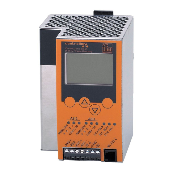
On this manual Overview: where is what? Overview: where is what? metal housing IP 20 device to unlock the device from a rail status LEDs of the fieldbus interface (option) text/graphics display 4 pushbuttons option: field bus interface (here: Ethernet) status LEDs (here: 2 masters) terminals for the voltage supply 24 V,... - Page 12 On this manual Overview: where is what?
-
Page 13: Safety Instructions
The manufacturer of the machine/equipment is responsible for the safety of the machine/equipment. WARNING Property damage or bodily injury when the notes in this manual are not adhered to! ifm electronic assumes no liability for this. ► The acting person must have read and understood the safety instructions and the corresponding chapters of this manual before performing any work on or with this device. - Page 14 Safety instructions Functions and features...
-
Page 15: System Requirements
System requirements Information concerning the device separate basic instructions of the device manual This manual describes the AS-i controller e device family from ifm electronic gmbh with the option Ethernet TCP/IP interface. Information concerning the software separate basic instructions of the device manual Required accessories Basic functions ... - Page 16 System requirements Required accessories...
-
Page 17: Function
Function Overview Function Basic functions separate basic instructions of the device manual Fieldbus interface (option) separate supplementary device manual Overview The programming Ethernet interface of the controller e can be used for project and data transmission. - from the PC to the controller e, as well as - from the controller e to the PC. -
Page 18: Data Management
Function Data management Data management The controller e consists of different devices: text/graphics display AS-i master 1 fieldbus interface (optional) central AS-i master 2 processing (optional) Ethernet programming interface unit (optional) SRAM memory RS-232C programming interface flash memory This manual exclusively describes the following subject: ... -
Page 19: Which Operating Modes Are There For The Plc In The Controller E
Function Which operating modes are there for the PLC in the controllere? Which operating modes are there for the PLC in the controller e ? Operating mode Meaning Behaviour at Modbus / fieldbus SPS program start > The PLC program stored in the At Modbus AS-i Slaves in the controller e is processed. -
Page 20: Project Transmission And Diagnosis Via Ethernet Interface
Function Project transmission and diagnosis via Ethernet interface Project transmission and diagnosis via Ethernet interface This section describes the project transmission and diagnosis (AS-i networks and projects) via a simple structure (PC - controller e with a point-to-point connection via Ethernet) as well as in an Ethernet network. -
Page 21: Step 1: Connect The Pc To The Controller E
Function Project transmission and diagnosis via Ethernet interface Here is the detailed description of the steps: Step 1: Connect the PC to the controller e ► Connect the LAN connection of the PC to the controller e . ► To do so, use a cross-over CAT5 Ethernet patch cable with an RJ45 connector on both sides, e.g.: article no. - Page 22 Function Project transmission and diagnosis via Ethernet interface System Setup Serial Port Baudrate Ethernet Setup ► Use [▼] to scroll to [Ethernet Setup] ▲▼ System Setup Serial Port Baudrate Ethernet Setup ► Select [Ethernet Setup] with [OK] ▲▼ Ethernet Setup IP Address Subnet Mask To set the IP address, DHCP must be switched off.
- Page 23 Function Project transmission and diagnosis via Ethernet interface Ethernet Setup DHCP on DHCP off ► Select [DHCP OFF] with [OK] ▲▼ > "Wait!" is displayed Ethernet Setup Auto Negotiation DHCP Setup > Display of the menu [Ethernet Setup] ▲▼ ► Use [▲] to scroll to [IP-Adresse] Ethernet Setup IP Address Subnet Mask...
- Page 24 Function Project transmission and diagnosis via Ethernet interface Ethernet Setup IP Address Subnet Mask > Display of the menu [Ethernet Setup] ▲▼ ► Use [▼] to scroll to [Subnet Mask] Ethernet Setup IP Address Subnet Mask ► Select [Subnet Mask] with [OK] ▲▼...
-
Page 25: Step 3: Select The Target System And Write The Project
Function Project transmission and diagnosis via Ethernet interface NOTE In a local network the participants can only communicate if their IP addresses are from the same "family". Example: subnet mask = 255.255.255.0 Then the IP addresses of the first 3 address groups (where "255" is) must be identical for all participants. - Page 26 Function Project transmission and diagnosis via Ethernet interface ► Confirm with [OK] > The following (or similar) figure appears: ► Create the first POU. To do so, adopt the entries from the figure ( above). ► Confirm with [OK] > The following figure appears: ►...
-
Page 27: Step 4: Set The Communication Parameters
Function Project transmission and diagnosis via Ethernet interface ► Select [File] > [Save as...] to save the project in the requested directory as "DemoProj" ( right): Step 4: Set the communication parameters The cable alone does not enable the communication between the controller e and the PC. The same communication parameters must be set for both devices and the project. - Page 28 Function Project transmission and diagnosis via Ethernet interface > The following figure appears: ► Click [New…] Enter the parameters in the following dialogue window as shown in the window below > The following figure appears: ► Select the entry [Tcp/Ip(Level 2)] ►...
-
Page 29: Step 5: Transmit And Start The Project
Function Project transmission and diagnosis via Ethernet interface Step 5: Transmit and start the project ► Click [Online] > [Login] to activate the connection from the PC to the controller e : > The following message appears: Reason: in the project which is saved on the PC details have not yet been defined. -
Page 30: Step 6: Set-Up, Monitoring And Diagnosis Of The As-I System
Function Project transmission and diagnosis via Ethernet interface Step 6: Set-up, monitoring and diagnosis of the AS-i system First use the PLC configuration window: ► Click the tab [Resources] (below) ► Click the option [PLC configuration] > The following figure appears: In step 5 you copied the configuration data from the controller e to your PC into your project. -
Page 31: Step 7: Create The Boot Project And Save The Source Code
Function Project transmission and diagnosis via Ethernet interface Step 7: Create the boot project and save the source code When the controller e is switched off the device forgets all setting parameters. In the controller e you can non-volatilely save a boot project which loads all current settings when the device is switched on. At the latest when completing the project you must create a boot project to non-volatilely save the project in the controller e . -
Page 32: Step 8: Transmit The Source Code From The Controller E To The Pc (Service Case)
Function Project transmission and diagnosis via Ethernet interface Step 8: Transmit the source code from the controller e to the PC (service case) Your project was transmitted as source code from the PC to the controller e and is available there ( step 7). - Page 33 Function Project transmission and diagnosis via Ethernet interface ► Convince yourself that the copied project which you have transmitted from the controller e corresponds to your original project. 4-17...
-
Page 34: Ethernet Network Connection
Function Project transmission and diagnosis via Ethernet interface 4.5.2 Ethernet network connection page Connection between controller e point-to-point connection controller e controller e network connection here controller e client MODBUS/TCP server / client 4-33 controller e HTML page HTML data exchange 4-74 Overview Ethernet network connection An Ethernet network connection is to be implemented (... -
Page 35: Excursion: Global Network Variables / Exp Files
Function Project transmission and diagnosis via Ethernet interface Excursion: Global network variables / EXP files Global network variables are used for data exchange between controllers in the network. There is a difference between export and import variables: Export variables originate from the local project. Their values can be locally influenced. -
Page 36: Overview: Steps For Implementing An Ethernet Network Connection
Function Project transmission and diagnosis via Ethernet interface Overview: Steps for implementing an Ethernet network connection An Ethernet network connection is to be implemented ( page 4-18). For this the following steps are required: Step 1 ► Connect the devices via Ethernet ( page 4-20) Step 2 ►... -
Page 37: Step 3: Select The First Target System And Create A Project
Function Project transmission and diagnosis via Ethernet interface Step 3: Select the first target system and create a project Three projects are to be written: one for each controller e in the network. The projects differ only slightly, the main differences concern the global variables and the executable part. Below please find a more detailed description of the projects. - Page 38 Function Project transmission and diagnosis via Ethernet interface > The following (or similar) figure appears: ► Create the first POU. To do so, adopt the entries from the figure ( above). ► Confirm with [OK] > The following figure appears: ►...
-
Page 39: Step 4: Set The Communication Parameters
Function Project transmission and diagnosis via Ethernet interface Step 4: Set the communication parameters The same communication parameters must be set for the PC, the controller e and the project. ► Select [Online] > [Communication Parameters...] to call the following dialogue: >... - Page 40 Function Project transmission and diagnosis via Ethernet interface > The following figure appears: ► Select the entry [Tcp/Ip(Level 2)] ► Confirm with [OK] > The following figure appears: ► Enter the corresponding IP address of the controller (see step 2) ►...
-
Page 41: Step 5: Activate The Network Variable Support
Function Project transmission and diagnosis via Ethernet interface Step 5: Activate the network variable support ► Click the tab [Resources] in CoDeSys ► Double-click [Target Settings] > The following figure appears: ► Double-click the tab [Network functionality] ► Activate the field [Support network variables] ►... -
Page 42: Step 6: Integrate Libraries
Function Project transmission and diagnosis via Ethernet interface Step 6: Integrate libraries ► Menu [Window] > [Library Manager] > Display of the libraries already loaded (here: only standard.lib) ► Menu [Insert] > [Additional Library... Ins] ► Key [Ins] ► Insert the following libraries: ... -
Page 43: Step 7: Complete And Transmit The Project (Global Network Variables)
Function Project transmission and diagnosis via Ethernet interface Step 7: Complete and transmit the project (Global network variables) To demonstrate the data exchange via global network variables you now write a project for each of the three controller e devices. These projects are suitable for this purpose mainly due to the global variable lists which they contain. - Page 44 Function Project transmission and diagnosis via Ethernet interface ► Click [Object Properties...] ( figure) > Display of the window "Properties": ► Click [Add network] > The following figure appears: ► Enter the properties of the list similarly as shown, but: ...
-
Page 45: Excursion: Variable List Identifier (Cob Id)
Function Project transmission and diagnosis via Ethernet interface Excursion: variable list identifier (COB ID) Here we operate with variable lists which are exported from one controller e device and imported to one or more controller e devices. This assignment of the variable lists is marked by a COB ID. This correlation is shown in the figure below. -
Page 46: Continuation Of Step 7
Function Project transmission and diagnosis via Ethernet interface Continuation of step 7: ► In the window [Properties] of the global variable list: Click [Settings...] > The following figure appears: ► As broadcast address enter the IP address of controller e 1, but: replace the value in the last group by "255"... - Page 47 Function Project transmission and diagnosis via Ethernet interface ► Enter the properties and settings of this list ( figure below) For import: activate [Import before compile] and [Read]! ► Click [Settings...] > The following figure appears: ► As broadcast address enter the IP address of controller e 2, but: replace the value in the last group by "255".
-
Page 48: Step 9: Transmit Projects
Function Project transmission and diagnosis via Ethernet interface For each project we will write only one POU which increases the contents of the corresponding variables (x1, x2 or x3) by 1 in each PLC cycle. In our example we show the POU PLC_PRG for DemoProj1.pro (... -
Page 49: Modbus/Tcp Server / Client
Function Project transmission and diagnosis via Ethernet interface 4.5.3 MODBUS/TCP server / client page Connection between controller e point-to-point connection controller e controller e network connection 4-18 controller e client MODBUS/TCP server / client here controller e HTML page HTML data exchange 4-74 Overview MODBUS/TCP server / client... -
Page 50: Valid Modbus Addresses And Their Meaning
Function Project transmission and diagnosis via Ethernet interface Valid Modbus addresses and their meaning Modbus address [words] Access IEC addresses Size Content start r = read [words] w = write dec. hex. dec. from controller e PLC status ( page 4-36) —... - Page 51 Function Project transmission and diagnosis via Ethernet interface Modbus address [words] Access IEC addresses Size Content start r = read [words] w = write dec. hex. dec. from %IW32.88 %IW32.91 8469 2115 8472 LPF ( page 4-58) %IW32.92 %IW32.95 8473 2119 8476 LPS (...
-
Page 52: Modbus Address For Controller E Plc Status
Function Project transmission and diagnosis via Ethernet interface Modbus address for controller e PLC status Modbus address Data content (16 bits = 1 word) status value = 1 PLC is in the operating mode RUN status value = 2 PLC is in the operating mode STOP 1024 status value = 8 ... -
Page 53: Modbus Addresses Of The Digital Slave Inputs And Outputs
Function Project transmission and diagnosis via Ethernet interface Modbus addresses of the digital slave inputs and outputs Modbus addresses Bits of the Modbus address Master 1 Master 1 Master 2 Master 2 15…12 7…4 inputs outputs inputs outputs Slave data bits 4096 4525 8192... -
Page 54: Iec Addresses In The Plc Of The Controller E For The Digital Slave Inputs And Outputs
Function Project transmission and diagnosis via Ethernet interface IEC addresses in the PLC of the controller e for the digital slave inputs and outputs Data area Type of Identification Slave address Data bit access 1 = S/A slave on master 1 1 = slave 1 if type of access = X: I = input... - Page 55 Function Project transmission and diagnosis via Ethernet interface IEC addresses (PLC in controller e ) Inputs / outputs to slave address Master 1 Master 1 Master 2 Master 2 inputs outputs inputs outputs %IB1.31 %QB1.31 %IB2.31 %QB2.31 31 (A) %IB11.1 %QB11.1 %IB21.1 %QB21.1...
-
Page 56: Modbus Addresses For The Master Flags
Function Project transmission and diagnosis via Ethernet interface Modbus addresses for the master flags Modbus address IEC address Bit = TRUE means: (PLC in controller e ) Master 1 Master 2 "No Slave Reset" 4128 8224 When executing the function "Config all" (via the menu or command channel of the controllere) the slaves are NOT reset, as described in the AS-i specification. -
Page 57: Modbus Addresses For The Analogue Slave Inputs And Outputs
Function Project transmission and diagnosis via Ethernet interface Modbus addresses for the analogue slave inputs and outputs Modbus addresses Data content (16 bits = word) Slave address Master 1 Master 1 Master 2 Master 2 Channel Description inputs outputs inputs outputs 4130 4559... - Page 58 Function Project transmission and diagnosis via Ethernet interface Modbus addresses Data content (16 bits = word) Slave address Master 1 Master 1 Master 2 Master 2 Channel Description inputs outputs inputs outputs 3rd channel single slave or: 4162 4591 8258 8687 1st channel B slave 4th channel single slave or:...
- Page 59 Function Project transmission and diagnosis via Ethernet interface Modbus addresses Data content (16 bits = word) Slave address Master 1 Master 1 Master 2 Master 2 Channel Description inputs outputs inputs outputs 4195 4624 8291 8720 1st channel S/A slave 4196 4625 8292...
- Page 60 Function Project transmission and diagnosis via Ethernet interface Modbus addresses Data content (16 bits = word) Slave address Master 1 Master 1 Master 2 Master 2 Channel Description inputs outputs inputs outputs 4th channel single slave or: 4228 4657 8324 8753 2nd channel B slave 4229...
-
Page 61: Status Information Of Analogue Slaves
Function Project transmission and diagnosis via Ethernet interface Modbus addresses Data content (16 bits = word) Slave address Master 1 Master 1 Master 2 Master 2 Channel Description inputs outputs inputs outputs 3rd channel single slave or: 4262 4691 8358 8787 1st channel B slave 4th channel single slave or:... - Page 62 Function Project transmission and diagnosis via Ethernet interface Word analogue data channel 0 from/for slave 2 or: analogue data channel 0 from/for slave 2A analogue data channel 1 from/for slave 2 or: analogue data channel 1 from/for slave 2A analogue data channel 2 from/for slave 2 or: analogue data channel 0 from/for slave 2B analogue data channel 3 from/for slave 2 or: analogue data channel 1 from/for slave 2B...
-
Page 63: Iec Addresses In The Plc Of The Controller E For The Analogue Slave Inputs And Outputs
Function Project transmission and diagnosis via Ethernet interface IEC addresses in the PLC of the controller e for the analogue slave inputs and outputs % Q W Data area Type of Identification Slave address Data channel access 1st channel S/A slave 2nd channel S/A slave 1 = slave 1 3rd channel single slave or:... - Page 64 Function Project transmission and diagnosis via Ethernet interface IEC addresses Data content (16 bits = word) (PLC in controller e ) Slave address Master 1 Master 1 Master 2 Master 2 Channel Description inputs outputs inputs outputs %IW21.5.1 %QW21.5.1 %IW22.5.1 %QW22.5.1 2nd channel S/A slave 3rd channel single slave or:...
- Page 65 Function Project transmission and diagnosis via Ethernet interface IEC addresses Data content (16 bits = word) (PLC in controller e ) Slave address Master 1 Master 1 Master 2 Master 2 Channel Description inputs outputs inputs outputs 4th channel single slave or: %IW21.11.3 %QW21.11.3 %IW22.11.3...
- Page 66 Function Project transmission and diagnosis via Ethernet interface IEC addresses Data content (16 bits = word) (PLC in controller e ) Slave address Master 1 Master 1 Master 2 Master 2 Channel Description inputs outputs inputs outputs %IW21.18.1 %QW21.18.1 %IW22.18.1 %QW22.18.1 2nd channel S/A slave 3rd channel single slave or:...
- Page 67 Function Project transmission and diagnosis via Ethernet interface IEC addresses Data content (16 bits = word) (PLC in controller e ) Slave address Master 1 Master 1 Master 2 Master 2 Channel Description inputs outputs inputs outputs 4th channel single slave or: %IW21.24.3 %QW21.24.3 %IW22.24.3...
- Page 68 Function Project transmission and diagnosis via Ethernet interface IEC addresses Data content (16 bits = word) (PLC in controller e ) Slave address Master 1 Master 1 Master 2 Master 2 Channel Description inputs outputs inputs outputs %IW21.31.1 %QW21.31.1 %IW22.31.1 %QW22.31.1 2nd channel S/A slave 3rd channel single slave or:...
-
Page 69: Modbus Addresses For Configuration Data (Cdi) Of The Slaves
Function Project transmission and diagnosis via Ethernet interface Modbus addresses for configuration data (CDI) of the slaves CDI = Configuration Data Image IEC addresses Modbus addresses Bits / data content (PLC in controller e ) 15…12 11…8 7…4 3…0 Master 1 Master 2 Master 1 Master 2... -
Page 70: Iec Addresses In The Plc Of The Controller E For Configuration Data (Cdi) Of The Slaves
Function Project transmission and diagnosis via Ethernet interface IEC addresses Modbus addresses Bits / data content (PLC in controller e ) 15…12 11…8 7…4 3…0 Master 1 Master 2 Master 1 Master 2 XID2 XID1 current projected current projected configuration data of slave current projected current... -
Page 71: Modbus Addresses For Parameter Data Of The Slaves
Function Project transmission and diagnosis via Ethernet interface Modbus addresses for parameter data of the slaves IEC addresses Modbus addresses Bits (PLC in controller e ) 15…12 11…8 7…4 3…0 Master 1 Master 2 Master 1 Master 2 current reflected current reflected parameter data of slave... -
Page 72: Modbus Addresses For The Slave List Las (List Of Active Slaves)
Function Project transmission and diagnosis via Ethernet interface Modbus addresses for the slave list LAS (list of active slaves) Modbus addresses Bits IEC addresses AS-i slave addresses (PLC in controller e ) Master 1 Master 2 4365 8461 15(A) 14(A) 13(A) 12(A) 11(A) 10(A) 9(A) 8(A) 7(A) -
Page 73: Modbus Addresses For The Slave List Lds (List Of Detected Slaves)
Function Project transmission and diagnosis via Ethernet interface Modbus addresses for the slave list LDS (list of detected slaves) Modbus addresses Bits IEC addresses AS-i slave addresses (PLC in controller e ) Master 1 Master 2 4369 8465 15(A) 14(A) 13(A) 12(A) 11(A) 10(A) 9(A) 8(A) 7(A) -
Page 74: Modbus Addresses For The Slave List Lpf (List Of Slaves With Periphery Faults)
Function Project transmission and diagnosis via Ethernet interface Modbus addresses for the slave list LPF (list of slaves with periphery faults) Modbus addresses Bits IEC addresses AS-i slave addresses (PLC in controller e ) Master 1 Master 2 4373 8469 15(A) 14(A) 13(A) 12(A) 11(A) 10(A) 9(A) 8(A) -
Page 75: Modbus Addresses For The Slave List Lps (List Of Projected Slaves)
Function Project transmission and diagnosis via Ethernet interface Modbus addresses for the slave list LPS (list of projected slaves) Modbus addresses Bits IEC addresses AS-i slave addresses (PLC in controller e ) Master 1 Master 2 4377 8473 15(A) 14(A) 13(A) 12(A) 11(A) 10(A) 9(A) 8(A) 7(A) -
Page 76: Modbus Addresses For The Slave Telegram Error Counters
Function Project transmission and diagnosis via Ethernet interface Modbus addresses for the slave telegram error counters IEC addresses Modbus addresses Telegram error counter of slave (PLC in controller e ) (16 bits = 1 word) Master 1 Master 2 Master 1 Master 2 4461 8557... -
Page 77: Iec Addresses In The Plc Of The Controller E For The Slave Telegram Error Counter
Function Project transmission and diagnosis via Ethernet interface IEC addresses Modbus addresses Telegram error counter of slave (PLC in controller e ) (16 bits = 1 word) Master 1 Master 2 Master 1 Master 2 4502 8598 11 B %IW31.217 %IW32.217 4503 8599... -
Page 78: Modbus Addresses For The Configuration Error Counter
Function Project transmission and diagnosis via Ethernet interface Modbus addresses for the configuration error counter IEC addresses Modbus addresses Configuration error counter of AS-i master (PLC in controller e ) (16 bits = 1 word) Master 1 Master 2 Master 1 Master 2 4523 8619... -
Page 79: Modbus Addresses For The Request Data Of The Host Command Channel
Function Project transmission and diagnosis via Ethernet interface Modbus addresses for the request data of the host command channel Modbus addresses Master 1 Master 2 4794 8890 echo byte of the request request / status 4795 8891 command code 4796 8892 data (0) 4797... -
Page 80: Modbus Addresses For The Response Data Of The Host Command Channel
Function Project transmission and diagnosis via Ethernet interface Modbus addresses for the response data of the host command channel Modbus addresses Master 1 Master 2 4813 8909 echo byte of the response status 4814 8910 command code 4815 8911 data (0) 4816 8912 data (1) -
Page 81: Modbus Addresses For The Fieldbus Data From/To The Plc Of The Controller E
Function Project transmission and diagnosis via Ethernet interface Modbus addresses for the fieldbus data from/to the PLC of the controller e IEC addresses Modbus addresses (PLC in controller e ) Data content (16 bits = 1 word) Data to the Data from Data to the Data from... - Page 82 Function Project transmission and diagnosis via Ethernet interface IEC addresses Modbus addresses (PLC in controller e ) Data content (16 bits = 1 word) Data to the Data from Data to the Data from the PLC the PLC 12329 12393 user-defined %IW0.41 %QW0.41...
-
Page 83: Modbus Addresses For The Extended Data From/To The Plc Of The Controller E
Function Project transmission and diagnosis via Ethernet interface Modbus addresses for the extended data from/to the PLC of the controller e IEC addresses Modbus addresses (PLC in controller e ) Data content (16 bits = 1 word) Data to the Data from Data to the Data from... - Page 84 Function Project transmission and diagnosis via Ethernet interface IEC addresses Modbus addresses (PLC in controller e ) Data content (16 bits = 1 word) Data to the Data from Data to the Data from the PLC the PLC 12457 12713 user-defined %IW4.41 %QW4.41...
- Page 85 Function Project transmission and diagnosis via Ethernet interface IEC addresses Modbus addresses (PLC in controller e ) Data content (16 bits = 1 word) Data to the Data from Data to the Data from the PLC the PLC 12499 12755 user-defined %IW4.83 %QW4.83...
- Page 86 Function Project transmission and diagnosis via Ethernet interface IEC addresses Modbus addresses (PLC in controller e ) Data content (16 bits = 1 word) Data to the Data from Data to the Data from the PLC the PLC 12541 12797 user-defined %IW4.125 %QW4.125...
- Page 87 Function Project transmission and diagnosis via Ethernet interface IEC addresses Modbus addresses (PLC in controller e ) Data content (16 bits = 1 word) Data to the Data from Data to the Data from the PLC the PLC 12583 12839 user-defined %IW4.167 %QW4.167...
- Page 88 Function Project transmission and diagnosis via Ethernet interface IEC addresses Modbus addresses (PLC in controller e ) Data content (16 bits = 1 word) Data to the Data from Data to the Data from the PLC the PLC 12625 12881 user-defined %IW4.209 %QW4.209...
-
Page 89: Iec Addresses In The Plc Of The Controller E For The Extended Data From/To The Plc Of The Controller E
Function Project transmission and diagnosis via Ethernet interface IEC addresses Modbus addresses (PLC in controller e ) Data content (16 bits = 1 word) Data to the Data from Data to the Data from the PLC the PLC 12667 12923 user-defined %IW4.251 %QW4.251... -
Page 90: Data Exchange Html Page - Controller E
Function Project transmission and diagnosis via Ethernet interface 4.5.4 Data exchange HTML page – controller e page Connection between controller e point-to-point connection controller e controller e network connection 4-18 controller e client MODBUS/TCP server / client 4-33 controller e HTML page HTML data exchange here Overview HTML data exchange... -
Page 91: Setting Up An Own Web Page
Function Project transmission and diagnosis via Ethernet interface Setting up an own web page An own web page is to be realised on the controller e . For this the following steps are required: Step 1 ► Connect the devices via Ethernet ( page 4-75) Step 2 ►... -
Page 92: Step 3: Open The Html Page In The Browser
Function Project transmission and diagnosis via Ethernet interface Step 3: Open the HTML page in the browser On delivery, a start page is stored in the web server of the controller e . This page is displayed when you access the IP address of the controller e with the HTTP protocol in a browser. An example of calling the start page of the controller e with the IP address 192.168.10.11 is shown in the following figure. -
Page 93: Step 4: Address The File Server Via Ftp
Function Project transmission and diagnosis via Ethernet interface NOTE To allow the web page to be updated it must be possible to run Java applets in the browser (e.g. by Java 2 Runtime Environment 5.0). Step 4: Address the file server via FTP As shown in the following example the file server in the controller e can be called via the browser / Explorer. - Page 94 Function Project transmission and diagnosis via Ethernet interface If RAM disk in the controller e <10.120: > The following figure appears: ► User name = ftpuser Do not enter a password ► Click [Login] To all controller e devices the following applies: >...
-
Page 95: Step 5: Edit The Web Page
Function Project transmission and diagnosis via Ethernet interface Step 5: Edit the web page ► Right-click the file name user.html ► Select [Edit the source code] In the following we describe the device-specific particularities of the HTML program code. Please find a description of the HTML orders in the appropriate technical literature. -
Page 96: Call The Function Cyclically
Function Project transmission and diagnosis via Ethernet interface case of a fault the value "-1" is returned. The content of the Modbus register is returned in the value range 0…65535. public void writeSingleRegister(int ref, int value) writeSingleRegister is used to write a register of a Modbus register model. With the parameter "value"... -
Page 97: Step 6: Loading And Testing The Modified Web Page
Function Project transmission and diagnosis via Ethernet interface Step 6: Loading and testing the modified web page There are two possibilities to open an application-specific web page: The page shall be accessible via the link [User-Site] from the supplied start page: ... - Page 98 Function Project transmission and diagnosis via Ethernet interface 4-82...
-
Page 99: Menu
Menu Menu "Ethernet Setup"“ Menu NOTE In this manual the menu texts are all indicated in English. Basic functions separate basic instructions of the device manual Menu "Ethernet Setup"“ Quick setting of the Ethernet programming interface, reading of the parameter data (password level 1 required). - Page 100 Menu Menu "Ethernet Setup"“ Menu tree Explanation System Setup > Display: automatic negotiation of the network connection Ethernet Setup parameters Auto Negotiation ► Selection: Use [▲] or [▼] to switch the function on or off. ► Confirm with [OK] ► (Cancel with [ESC]) System Setup >...
-
Page 101: Operation
Operation The Modbus command channel Operation The Modbus command channel In the Modbus address space a command channel with a length of 19 words is defined for each AS-i master. A Modbus TCP client operates as host system. Modbus addresses Access Size Contents... -
Page 102: Overview Of The Commands In The Modbus Command Channel
Operation The Modbus command channel The command status indicates the status of the command channel: 0#65 command request by the host 0#6A command is being processed 0#6B command aborted due to an error 0#6C abort after timeout during command processing 0#6D command completed, but response data not yet consistent 0#6E... - Page 103 Operation The Modbus command channel Command number page Description Decimal Hexadecimal acyclic manufacturer-specific read call to an AS-i slave with 0#27 CTT2 profile (S-7.5.5, S-7.A.5 or S-B.A.5) 6-47 - available from master profile M4 onwards - 0#32 read current configuration of AS-i slaves 0(A)...15(A) 0#33 read current configuration of AS-i slaves 16(A)...31(A) 6-51...
-
Page 104: Command 0 (0#00): No Execution Of A Command
Operation The Modbus command channel 6.1.2 Command 0 (0#00): no execution of a command Request from host: Word user ID command request = 0#65 0#00 command number = 0#00 3…19 ignored ignored Example: user ID changes to 0#03, 0#0365 command request with 0#65 0#0000 0#00 = command number 0 3…18... -
Page 105: Command 1 (0#01): Write Parameters To A Connected As-I Slave
Operation The Modbus command channel 6.1.3 Command 1 (0#01): Write parameters to a connected AS-i slave Request from host: Word user ID command request = 0#65 0#00 command number = 0#01 ignored AS-i slave address parameter value to ignored be written 5…19 ignored Legend:... -
Page 106: Response From Controller E In The Case Of An Error
Operation The Modbus command channel Response from controller e in the case of an error: Word user ID command status = 0#6B ignored reflected command number = 0#01 0#00 error code Possible error codes: no slave response or 0#01 master is in the offline mode when calling the command 0#0A slave is not in LAS 0#0B... -
Page 107: Request From Host
Operation The Modbus command channel 6.1.4 Command 3 (0#03): Adopt and save currently connected AS-i slaves in the configuration Request from host: Word user ID command request = 0#65 ignored command number = 0#03 3…19 ignored Example: user ID changes to 0#0C, 0#0C65 command request with 0#65 0#0003... -
Page 108: Response From Controller E In The Case Of An Error
Operation The Modbus command channel Response from controller e in the case of an error: Word user ID command status = 0#6B 0#00 reflected command number = 0#03 0#00 error code 4…19 ignored Possible error codes: 0#14 master is not in the normal mode Example: user ID changes to 0#0C, 0#0C6B... -
Page 109: Command 4 0#04): List Of The Projected As-I Slaves (Lps)
Operation The Modbus command channel 6.1.5 Command 4 0#04): List of the projected AS-i slaves (LPS) Request from host: Word user ID command request = 0#65 0#00 command number = 0#04 15(A) 14(A) 13(A) 12(A) 11(A) 10(A) 9(A) 8(A) 7(A) 6(A) 5(A) 4(A) -
Page 110: Response From Controller E In The Case Of An Error
Operation The Modbus command channel Response from controller e in the case of an error: Word user ID command status = 0#6B 0#00 reflected command number = 0#04 ignored error code Possible error codes: 0#14 master is not in the configuration mode Example: user ID changes to 0#02, 0#026B... -
Page 111: Command 5 (0#05): Set The Operating Mode Of The As-I Master
Operation The Modbus command channel 6.1.6 Command 5 (0#05): Set the operating mode of the AS-i master Request from host: Word user ID command request = 0#65 0#00 command number = 0#05 ignored operating mode 4…17 ignored 18…19 reserved Example: user ID changes to 0#01, 0#0165 command request with 0#65... -
Page 112: Command 6 (0#06): Readdress A Connected As-I Slave
Operation The Modbus command channel 6.1.7 Command 6 (0#06): Readdress a connected AS-i slave Request from host: Word user ID command request = 0#65 0#00 command number = 0#06 ignored old slave address ignored new slave address 5…17 ignored 18…19 reserved Legend: Bit for addressing A or B slaves... -
Page 113: Response From Controller E In The Case Of An Error
Operation The Modbus command channel Response from controller e in the case of an error: Word user ID command status = 0#6B 0#00 reflected command number = 0#06 ignored error code Possible error codes: no slave response or 0#01 master is in the offline mode when calling the command 0#02 no slave with the old address found 0#03... -
Page 114: Command 7 (0#07): Set The Auto Address Mode Of The As-I Master
Operation The Modbus command channel 6.1.8 Command 7 (0#07): Set the auto address mode of the AS-i master Request from host: Word user ID command request = 0#65 0#00 command number = 0#07 ignored automatic addressing 4…17 ignored 18…19 reserved Example: user ID changes to 0#04, 0#0465... -
Page 115: Command 9 (0#09): Change The Extended Id Code 1 In The Connected As-I Slave
Operation The Modbus command channel 6.1.9 Command 9 (0#09): Change the extended ID code 1 in the connected AS-i slave Request from host: Word user ID command request = 0#65 0#00 command number = 0#09 ignored slave address ignored new "extended ID code 1" 5…17 ignored 18…19... -
Page 116: Response From Controller E In The Case Of An Error
Operation The Modbus command channel Response from controller e in the case of an error: Word user ID command status = 0#6B 0#00 reflected command number = 0#09 0#00 error code Possible error codes: no slave response or 0#01 master is in the offline mode when calling the command 0#02 no slave with the address found 0#03... -
Page 117: Request From Host
Operation The Modbus command channel 6.1.10 Command 10...20 (0#0A...0#14): Force analogue data transmission directly to / from 3 AS-i slaves in each case Request from host: Word user ID command request = 0#65 0#00 command number = 0#0A…0#14 output data AS-i slave 1(A), channel 0 output data AS-i slave 1(A), channel 1 output data AS-i slave 1, channel 2 or output data AS-i slave 1B, channel 0... - Page 118 Operation The Modbus command channel Example: user ID changes to 0#01, 0#0165 command request with 0#65 0#000A 0#0A = command number 10 0#0169 output data AS-i slave 1, channel 0 0#0202 output data AS-i slave 1, channel 1 0#0395 output data AS-i slave 1, channel 2 0#1033 output data AS-i slave 1, channel 3 overflow and valid bits for AS-i slave 1:...
-
Page 119: Response From Controller E
Operation The Modbus command channel Response from controller e : Word user ID command status = 0#6F 0#00 reflected command number = 0#0A…0#14 input data or reflected output data AS-i slave 1(A), channel 0 input data or reflected output data AS-i slave 1(A), channel 1 input data or reflected output data AS-i slave 1, channel 2 or input data or reflected output data AS-i slave 1B, channel 0 input data or reflected output data AS-i slave 1, channel 3 or... - Page 120 Operation The Modbus command channel Command number Slaves Decimal Hexadecimal 0#0A 0#0B 0#0C 0#0D 0#0E 0#0F 0#10 0#11 0#12 0#13 0#14 – – Example: user ID changes to 0#01, 0#016F command status is "completed" = 0#6F (no error) 0#000A 0#0A = reflected command number 10 slave 1 is a 4-channel input slave: 0#3169 input data AS-i slave 1, channel 0...
-
Page 121: Request From Host
Operation The Modbus command channel 6.1.11 Command 21 (0#15): Read the ID string of an AS-i slave with profile S-7.4 Request from host: Word user ID command request = 0#65 AS-i slave address command number = 21 (0#15) 3…19 ignored Example: user ID changes to 0#02, 0#0265... - Page 122 Operation The Modbus command channel Characterises the slave concerning functionality and data structure Length: 5 bits Permitted values: 0...31 Meaning: E type 0 = reserved 1 = transmitted values are measured values 2 = transmitted values are 16 digital bit values 3 = normal operation in 4-bit mode (4E/4A) 4...31 = reserved Direction of data for the devices with E type <>...
-
Page 123: Response From Controller E In The Case Of An Error
Operation The Modbus command channel Response from controller e in the case of an error: Word user ID command status = 0#6B 0#00 reflected command number = 0#15 0#00 error code Possible error codes: 0#0C faulty S-7.4 protocol sequence 0#0D S-7.4 protocol aborted (timeout) 0#0E invalid AS-i slave address for the S-7.4 protocol (e.g. -
Page 124: Command 28 (0#1C): Deactivate The Slave Reset When Changing To The Protected Mode
Operation The Modbus command channel 6.1.12 Command 28 (0#1C): Deactivate the slave reset when changing to the protected mode Request from host: Word user ID command request = 0#65 0#00 command number = 28 (0#1C) ignored with / without offline phase 4…19 ignored Example:... -
Page 125: Request From Host
Operation The Modbus command channel 6.1.13 Command 31 (0#1F): One-time execution of the "Extended Safety Monitor Protocol" in the "Safety at work" monitor Request from host: Word user ID command request = 0#65 0#00 command number = 31 (0#1F) AS-i slave address sub command (1...31 4…17... - Page 126 Operation The Modbus command channel Description of the different fields: Word no. 4: LEDs OSSD 1 LEDs OSSD 2 Meaning green: contacts of the output circuits closed yellow: startup / restart disable active yellow flashing or red: contacts of the output circuits open red flashing: error on the level of the monitored AS-i components reserved...
- Page 127 Operation The Modbus command channel 1st to 6th colour output circuit 1/2: Meaning green, continuous green, flashing yellow, continuous yellow, flashing red, continuous red, flashing grey, off Example („Safety at work“ monitor has not switched): user ID changes to 0#07, 0#076F command status is "completed"...
-
Page 128: Response From Controller E In The Case Of An Error
Operation The Modbus command channel Response from controller e in the case of an error: Word user ID command status = 0#6B 0#00 reflected command number = 0#1F 0#00 error code Possible error codes: 0#00… general errors during command processing 0#02 0#0A…... - Page 129 Operation The Modbus command channel 6.1.14 Command 33 (0#21): Read the diagnosis string of an AS-i slave with profile S-7.4 Request from host: Word user ID command request = 0#65 reserved = 0 AS-i slave address command number = 33 (0#21) 3…17 ignored field number (0#00 / 0#01)
- Page 130 Operation The Modbus command channel Example: user ID changes to 0#07, 0#076F command status is "completed" = 0#6F (no error) S = 0: last sequence, 0#0621 slave address = 3(A), = 00000110 0#21= reflected command number 33 0#8621 the most significant bit changes after each execution 0#2D01 1st word of the diagnosis data of slave 3(A) 0#0203...
-
Page 131: Request From Host
Operation The Modbus command channel 6.1.15 Command 34 (0#22): Read the parameter string of an AS-i slave with profile S-7.4 Request from host: Word user ID command request = 0#65 reserved = 0 AS-i slave address command number = 34 (0#22) 3…17 ignored field number (0#00 / 0#01) - Page 132 Operation The Modbus command channel Example: user ID changes to 0#08, 0#086F command status is "completed" = 0#6F (no error) slave address = 3(A), = 00000110 0#0622 0#22 = reflected command number 34 0#8622 the most significant bit changes after each execution 0#1234 1st word of the parameter string of slave 3(A) 0#5678...
-
Page 133: Request From Host
Operation The Modbus command channel 6.1.16 Command 35 (0#23): Write parameter string of an AS-i slave with the profile S-7.4 Request from host: Word user ID command request = 0#65 AS-i slave address command number = 35 (0#23) parameter string 1 parameter string 0 4…16 parameter strings 2…27... -
Page 134: Response From Controller E
Operation The Modbus command channel Response from controller e : Word user ID command status = 0#6F AS-i slave address reflected command number = 0#23 3...18 0#00 0#00 Legend: Sequence bit Length: 1 bit Permitted values: 0/1 Meaning: 0 = data transmission completed 1 = data transmission not yet completed, at least one more packet follows. -
Page 135: Ctt2 Profile (S-7.5.5, S-7.A.5 Or S-B.a.5)
Operation The Modbus command channel 6.1.17 Command 36 (0#24): Acyclic standard read call to an AS-i slave with CTT2 profile (S-7.5.5, S-7.A.5 or S-B.A.5) – available from master profile M4 onwards – Request from host: Word user ID command request = 0#65 AS-i slave address command number = 36 (0#24) number of bytes to be read... - Page 136 Operation The Modbus command channel Response from controller e in the normal case: Word user ID command status = 0#6F TG L32 reserved reflected command number = 0#24 parameter byte 0 parameter byte 1 4…16 parameter bytes 2...27 parameter byte 28 parameter byte 29 parameter byte 30 or parameter byte 31...
- Page 137 Operation The Modbus command channel Response from controller e in the case of an error (error detected by AS-i master): Word user ID command status = 0#6B reserved reflected command number = 0#24 0#00 error code Legend: Toggle Length: 1 bit Permitted values: 0/1 Meaning: value changes for each execution of the command Possible error codes:...
-
Page 138: Possible Error Codes
Operation The Modbus command channel Response from controller e in the case of an error (error detected by AS-i slave): Word user ID command status = 0#6B reserved reflected command number = 0#24 CTT2 error code error code = 0#E1 Legend: : Toggle Length: 1 bit... -
Page 139: Request From Host
Operation The Modbus command channel 6.1.18 Command 37 (0#25): Acyclic standard write call for an AS-i slave with CTT2 profile (S-7.5.5, S-7.A.5 or S-B.A.5) – available from master profile M4 onwards – Request from host: Word user ID command request = 0#65 AS-i slave address command number = 37 (0#25) number of bytes to be sent... -
Page 140: Response From Controller E In The Normal Case
Operation The Modbus command channel Response from controller e in the normal case: Word user ID command status = 0#6F reserved reflected command number = 0#25 Legend: Toggle Length: 1 bit Permitted values: 0/1 Meaning: value changes for each execution of the command Error bit Length: 1 bit Permitted values: 0/1... -
Page 141: Response From Controller E In The Case Of An Error (Error Detected By As-I Master)
Operation The Modbus command channel Response from controller e in the case of an error (error detected by AS-i master): Word user ID command status = 0#6B reserved reflected command number = 0#25 0#00 error code Possible error codes: 0#16 timeout during command processing wrong slave profile or 0#17... -
Page 142: Response From Controller E In The Case Of An Error (Error Detected By As-I Slave)
Operation The Modbus command channel Response from controller e in the case of an error (error detected by AS-i slave): Word user ID command status = 0#6B reserved reflected command number = 0#25 CTT2 error code error code = 0#E1 Possible CTT2 error codes: 0#00 no error... -
Page 143: Command 38 (0#26): Acyclic Manufacturer-Specific Read Call To An As-I Slave With Ctt2 Profile (S-7.5.5, S-.7.A.5 Or S-B.a.5)
Operation The Modbus command channel 6.1.19 Command 38 (0#26): Acyclic manufacturer-specific read call to an AS-i slave with CTT2 profile (S- 7.5.5, S-.7.A.5 or S-B.A.5) – available from master profile M4 onwards – Request from host: Word user ID command request = 0#65 AS-i slave address command number = 38 (0#26) reserved = 0... -
Page 144: Response From Controller E In The Normal Case
Operation The Modbus command channel Response from controller e in the normal case: Word user ID command status = 0#6F TG L32 reserved reflected command number = 0#26 parameter byte 0 parameter byte 1 4…16 parameter bytes 2...27 parameter byte 28 parameter byte 29 parameter byte 30 or parameter byte 31... -
Page 145: Response From Controller E In The Case Of An Error (Error Detected By As-I Master)
Operation The Modbus command channel Response from controller e in the case of an error (error detected by AS-i master): Word user ID command status = 0#6B reserved reflected command number = 0#26 0#00 error code Possible error codes: 0#16 timeout during command processing wrong slave profile or 0#17... -
Page 146: Possible Error Codes
Operation The Modbus command channel Response from controller e in the case of an error (error detected by AS-i slave): Word user ID command status = 0#6B reserved reflected command number = 0#26 CTT2 error code error code = 0#E1 Possible CTT2 error codes: 0#00 no error... -
Page 147: Request From Host
Operation The Modbus command channel 6.1.20 Command 39 (0#27): Acyclic standard manufacturer-specific write call to an AS-i slave with CTT2 profile (S-7.5.5, S-7.A.5 or S-B.A.5) – available from master profile M4 onwards – Request from host: Word user ID command request = 0#65 AS-i slave address command number = 39 (0#27) number of bytes to be sent... -
Page 148: Response From Controller E In The Normal Case
Operation The Modbus command channel Response from controller e in the normal case: Word user ID command status = 0#6F reserved reflected command number = 0#27 Legend: Toggle Length: 1 bit Permitted values: 0/1 Meaning: value changes for each command execution Error bit Length: 1 bit Permitted values: 0/1... -
Page 149: Response From Controller E In The Case Of An Error (Error Detected By As-I Master)
Operation The Modbus command channel Response from controller e in the case of an error (error detected by AS-i master): Word user ID command status = 0#6B reserved reflected command number = 0#27 0#00 error code Possible error codes: 0#16 timeout during command processing wrong slave profile or 0#17... -
Page 150: Response From Controller E In The Case Of An Error (Error Detected By As-I Slave)
Operation The Modbus command channel Response from controller e in the case of an error (error detected by AS-i slave): Word user ID command status = 0#6B reserved reflected command number = 0#27 CTT2 error code error code = 0#E1 Possible CTT2 error codes: 0#00 no error... -
Page 151: Request From Host
Operation The Modbus command channel 6.1.21 Command 50 (0#32): Read current configuration of AS-i slaves 0(A)...15(A) Request from host: Word user ID command request = 0#65 0#00 command number = 50 (0#32) 3…17 ignored 18…19 reserved Example: user ID changes to 0#02, 0#0265 command request with 0#65 0#0032... -
Page 152: Command 54 (0#36): Read Current Parameters Of A Connected As-I Slave
Operation The Modbus command channel 6.1.22 Command 54 (0#36): Read current parameters of a connected AS-i slave Request from host: Word user ID command request = 0#65 0#00 command number = 54 (0#36) 3…17 ignored 18…19 reserved Example: user ID changes to 0#06, 0#0665 command request with 0#65 0#0036... - Page 153 Operation The Modbus command channel Example: user ID changes to 0#06, 0#066F command status is "completed" = 0#6F (no error) 0#0036 0#36 = reflected command number 54 0#4321 parameters of slave 1 [value = 1] to slave 4 [value = 4] 0#8765 parameters of slave 5 [value = 5] to slave 8 [value = 8] …...
-
Page 154: Command 55 (0#37): Read Current As-I Slaves
Operation The Modbus command channel 6.1.23 Command 55 (0#37): Read current AS-i slaves Request from host: Word user ID command request = 0#65 0#00 command number = 55 (0#37) 3…17 ignored 18…19 reserved Example: user ID changes to 0#07, 0#0765 command request with 0#65 0#0037 0#37 = command number 55... - Page 155 Operation The Modbus command channel Example: user ID changes to 0#07, 0#076F command status is "completed" = 0#6F (no error) 0#0037 0#37 = reflected command number 55 LAS slaves 1(A) to 15(A): 0#0102 0102 = 0000 0001 0000 0010 slaves 1 and 8 are active LAS slaves 16(A) to 31(A): 0#8001 8001...
-
Page 156: Command 56 (0#38): Read Projected Configuration Of The As-I Slaves 1(A)
Operation The Modbus command channel 6.1.24 Command 56 (0#38): Read projected configuration of the AS-i slaves 1(A)...15(A) Request from host: Word user ID command request = 0#65 0#00 command number = 56 (0#38) 3…17 ignored 18…19 reserved Example: user ID changes to 0#02, 0#0265 command request with 0#65 0#0038... -
Page 157: Command 96 (0#60): Save Data Non-Volatilely In The Flash Memory Of The Controller E
Operation The Modbus command channel 6.1.25 Command 96 (0#60): Save data non-volatilely in the flash memory of the controller e Request from host: Word user ID command request = 0#65 0#00 command number = 96 (0#60) 0#00 area number 4…19 ignored Example: user ID changes to 0#09,... -
Page 158: Command 97 (0#61): Carry Out Various Settings In The Controller E
Operation The Modbus command channel 6.1.26 Command 97 (0#61): Carry out various settings in the controller e Request from host: Word user ID command request = 0#65 0#00 command number = 97 (0#61) 0#00 command number 4…19 parameters 1…16 Example: user ID changes to 0#08, 0#0865 command request with 0#65... -
Page 159: Command 102 (0#66): Retrieve The Status Of The Controller E Display
Operation The Modbus command channel 6.1.27 Command 102 (0#66): Retrieve the status of the controller e display Request from host: Word user ID command request = 0#65 0#00 command number = 102 (0#66) 0#00 command number 4…n parameter(s) (according to command number) Example: user ID changes to 0#07, 0#0765... - Page 160 Operation The Modbus command channel error 0#0001 process error occurred occurred Currently displayed 0#xxxx number of the current menu screen menu screen Activated 0#0000 display of menus in English system 0#0001 display of menus in the second system language (e.g. German) language Example: user ID changes to 0#07,...
-
Page 161: Command 105 (0#69): Read The Device Properties Of The Controller E
Operation The Modbus command channel 6.1.28 Command 105 (0#69): Read the device properties of the controller e Request from host: Word user ID command request = 0#65 0#00 command number = 105 (0#69) 3…17 ignored 18…19 reserved Example: user ID changes to 0#06, 0#0665 command request with 0#65 0#0069... - Page 162 Operation The Modbus command channel 0#01 PLC is in the RUN mode 0#02 PLC is in the STOP mode PLC mode 0#04 PLC stops at the breakpoint 0#08 gateway mode 0#01 Anybus Profibus DP 0#04 Anybus CANopen 0#05 Anybus DeviceNet fieldbus 0#09 Anybus Ethernet IT...
-
Page 163: Terms, Abbreviations
Terms, abbreviations Terms, abbreviations A/B slave Slave with an A or B being appended to its address number and which may therefore be present twice on the master. Address This is the "name" of the bus participant. All participants need a unique defined address so that the signals can be exchanged without problem. - Page 164 Terms, abbreviations DHCP DHCP = Dynamic Host Configuration Protocol = protocol for the dynamic configuration by the host DHCP is a protocol which offers the dynamic configuration of IP addresses and thus coherent information. The protocol supports the further use of IP-addresses which are only available in a limited number by a centralised management of the address assignment.
- Page 165 Terms, abbreviations Jitter By jitter is understood a slight fluctuation in accuracy in the transmission cycle when transmitting digital signals. In general jitter is an abrupt and undesired change of the signal characteristics in transmission technology. List of Active Slaves In this slave list the controller e enters the slaves detected as active for this AS-i master.
- Page 166 Terms, abbreviations Password In the menu [System Setup] in the menu item [Password] the operation can be restricted or enabled. When delivered, the device is in the user mode. By entering an invalid password (e.g. 1000) all menu items which can change settings are blocked.
- Page 167 Terms, abbreviations Remanent Remanent data is protected against data loss in case of power failure. The operating system for example automatically copies the remanent data to a flash memory as soon as the voltage supply falls below a critical value. If the voltage supply is available again, the operating system loads the remanent data back to the RAM memory.
- Page 168 Terms, abbreviations...
-
Page 169: Index
Index Index nn-n The indication of the page where you can find some information about the keyword is written in normal characters. The indication of the page where the keyword is detailed is written in italics. ii-i A/B slave ............. 7-1 Main menu............
Need help?
Do you have a question about the ecomot 300 AC1353 and is the answer not in the manual?
Questions and answers