Table of Contents
Advertisement
Quick Links
Advertisement
Table of Contents

Subscribe to Our Youtube Channel
Related Manuals for IFM Electronic Ecomat 300 AL1010


Summary of Contents for IFM Electronic Ecomat 300 AL1010
- Page 1 Device manual IO-Link Profibus master AL1010...
-
Page 2: Table Of Contents
IO-Link master Contents 1 Preliminary note � � � � � � � � � � � � � � � � � � � � � � � � � � � � � � � � � � � � � � � � � � � � � � � � � 4 2 Safety instructions �... - Page 3 IO-Link master 13�2 IO-Link features � � � � � � � � � � � � � � � � � � � � � � � � � � � � � � � � � � � � � � � � � � � 17 13�3 General features�...
-
Page 4: Preliminary Note
IO-Link master 1 Preliminary note This document applies to devices of the type "IO-Link master" (art� no� AL1010)� This document is intended for specialists� These specialists are people who are qualified by their appropriate training and their experience to see risks and to avoid possible hazards that may be caused during operation or maintenance of the device�... -
Page 5: Safety Instructions
IO-Link master 2 Safety instructions These instructions contain texts and figures concerning the correct handling of the device and must be read before installation or use� Observe the operating instructions� Non-observance of the instructions, operation which is not in accordance with use as prescribed below, wrong installation or incorrect handling can seriously affect the safety of operators and machinery�... -
Page 6: Documentation
IO-Link master ► Devices that are designed for mounting in housings or control cabinets must only be operated and controlled after they have been installed with the housing closed� Desktop or portable units must only be operated and controlled in enclosed housings�... -
Page 7: Product Description
IO-Link master 5 Product description 5.1 DI (digital input) The digital inputs receive the digital control signals from the process level� These signals are transferred to the higher-level automation device via the network/bus� The signal status is indicated via LEDs� The sensors are connected via M12 screw connectors�... -
Page 8: Scale Drawings
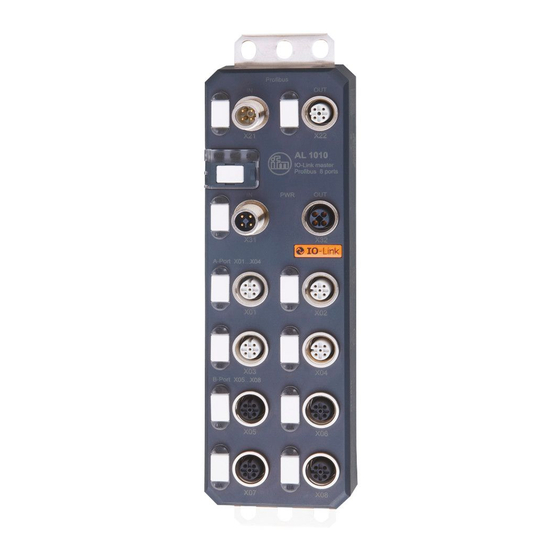
IO-Link master 7 Scale drawings 7.1 Dimensions of the screw holes in the fixing clips 8 Structure of the device 1� Fixing clips ( FE connection) 2� Network or bus connection (IN, OUT) 3� Connections for the supply voltages 4� Connections for inputs/outputs or IO-Link ports 5�... -
Page 9: 8�1 Diagnostic And Status Indicators
IO-Link master 8.1 Diagnostic and status indicators 8.1.1 Diagnostics The diagnostic indicators (green/yellow/red) indicate whether an error is present or not� In case of an error, they indicate the error type and location� The device is operating correctly if all green indicators are on� 8.1.2 Status The status indicators (yellow) indicate the signal state of the corresponding input/ output or of the IO-Link port�... -
Page 10: 9�1 Mechanical Strain
IO-Link master Data corruption and loss A minimum distance between the cabling and possible sources of interference (e�g�, machines, wel- ding equipment, power lines) is defined in the applicable regulations and standards� During system planning and installation, these regulations and standards must be taken into account and observed� Protect the bus cables from sources of electric/magnetic interference and mechanical strain�... -
Page 11: 9�5 Cable Routing Outside Buildings
IO-Link master ► Do not install network/bus cables together with or parallel to power supply lines� ► Separate network/bus cables on cable bridges or in cable ducts from power supply lines using isolating segments� ► Install network/bus cables as far away as possible from sources of interference, such as motors and welding equipment�... -
Page 12: 9�7 Surge Protection Measures
IO-Link master 1� Surge protective devices 2� Cable shielding 3� Equipotential bonding line 9.7 Surge protection measures ifm recommends wiring relay coils or motor coils to an RC element in order to protect the devices against interference� Depending on the application, the delay time of the relay can be increased by approximately 1 ms�... -
Page 13: 9�9 Installation Instructions
IO-Link master ► Ground the devices by means of the mounting screws of the fixing clips� 9.9 Installation instructions Electrostatic discharge The device contains components that can be damaged or destroyed by electrostatic discharge� When handling the device, observe the necessary safety precautions against electrostatic discharge (ESD) according to EN 61340-5-1 and IEC 61340-5-1�... - Page 14 IO-Link master ► Use standard M5 screws with toothed lock washer and self-locking nuts� ► Observe the maximum torque of the screws� Functional grounding ► Functional grounding is crucial for interference-free operation� Ground the device by means of the mounting screws of the fixing clips�...
-
Page 15: Scale Drawing
IO-Link master 10 Scale drawing 198,5 Scale drawing AL1010 11 Setting the address The device has rotary coding switches for setting the address and, if required, the transmission speed (see user manual for the respective network/bus system)� The rotary coding switches are located below a cover� ►... -
Page 16: Electrical Connection
IO-Link master Example: Profibus DP1 Setting address 77 Adjust the rotary coding switches using a suitable screwdriver (according to DIN 5264: blade width 3�0 mm or 2�5 mm)� Using an unsuitable tool may damage the rotary coding switches� 12 Electrical connection For the devices, a distinction is made between two voltages: –... -
Page 17: 12�3 Power Supply U
IO-Link master Damage to the electronics The current rating of the M12 connectors is 12 A per contact� Make sure that this value is not exceeded� Please note that the connection for the outgoing supply voltage is not monitored for overload� If the permissible current rating is exceeded, this may result in damage to the connectors�... -
Page 18: Technical Data
IO-Link master ● Short-circuit and overload protection of the sensor supply ● Protection rating IP 65/67 14 Technical data General data Housing material Pocan Weight [kg] 0�48 Ambient temperature (operation) [°C] -25 ���60 Ambient temperature (storage/transport) [°C] -25���85 Permissible humidity (operation) [%] 5���95 Air pressure (operation) [kPa] 70���106 kPa (up to 3000 m above... - Page 19 IO-Link master Maximum current consumption [A] Supply of the actuators Connection type M12 connector (T-coded) Number of poles Designation Supply voltage [V] 24 DC Nominal supply voltage range [V] 19���31�2 V DC (including all tole- rances, including ripple) Typical current consumption [mA] 30 mA ±...
- Page 20 IO-Link master Nominal load, inductive [VA] 12 (1.2 H; 12 Ω; with nominal voltage Signal delay [µs] max� 150 (at power on) Signal delay [µs] max� 200 (at power off) Switching frequency max� 5500 / s (with load current) Switching frequency max�...
-
Page 21: Connections
IO-Link master Bus connection / FE 500 AC, 50 Hz, 1 min 24 V supply (actuator supply)/ 500 AC, 50 Hz, 1 min 24 V supply (communications power and sensor supply, IO-Link ports) 24 V supply (actuator supply)/bus connection 500 AC, 50 Hz, 1 min 24 V supply (actuator supply)/FE 500 AC, 50 Hz, 1 min Mechanical tests... -
Page 22: 15�2 Profibus Pin Assignment
IO-Link master 15.2 Profibus pin assignment M12 connector for the in-coming bus line M12 connector for the outgoing bus line Signal Specification Description 5 V termination resistor RxD / TxD-N (A) A, RS-485, PD Inverted bus cable DGND RxD / TxD-P (B) B, RS-485, PU Non-inverted bus cable not used... -
Page 23: 15�4 Connecting Io-Link Ports And Inputs
IO-Link master 15.4 Connecting IO-Link ports and inputs IO-Link 1���8 (X01���X08): IO-Link ports 1���8 DI1���DI4 (X01���X04): Inputs 1���4 DI 1...4 IOL1...8 IO-Link A ports (X01���X04) IO-Link B ports (X05���X08) 1: 24 V DC (L+) 1: 24 V DC (L+) 2: DI 2: 24 V DC (U 3: GND (L-) 3: GND (L-) -
Page 24: 15�5 Connection Notes
IO-Link master 15.5 Connection notes Implement the FE connection using mounting screws, in order to ensure immunity to interference� To ensure IP 65/IP 67 protection, cover unused sockets with protective caps� Only supply the IO-Link master and the IO-Link devices with the voltage U und U provided at the terminal points�... -
Page 25: Local Status And Diagnostic Indicators
IO-Link master 17 Local status and diagnostic indicators 17.1 Indicators for bus and power supply Designation Colour Meaning State Description Green / Ready Green ON Device ready to operate yellow / red Yellow Firmware update is being performed flashing Green / Overvoltage or undervoltage at U yellow Temperature of the device is in the critical... -
Page 26: 17�2 Displaying The Io-Link Port And Inputs
IO-Link master Designation Colour Meaning State Description Group error Red ON Device-specific diagnostics present, e�g�, short circuit at the periphery� Hardware is faulty Device data or parameter data do not match Red OUT No error Green / Green ON Communications power/sensor voltage sensors sufficient Green OFF... - Page 27 IO-Link master Designation Colour Meaning State Description IO-Link LED Green / Status of Green ON In IO-Link mode yellow / red the IO-Link IO-Link communication present ports (X01 Green In IO-Link mode ��� X08) flashing no IO-Link communication Yellow ON In the DI or DO operating mode: the digital input or output is set Red ON...
-
Page 28: Profibus Data Model
IO-Link master 18 Profibus data model The unit has a modular design� The "Status/control module" is always located in slot 1, with 4 bytes of IN and OUT process data respectively� In slots 2 to 9, the operating mode as well as the process data length can be configured for the respective IO-Link port�... - Page 29 IO-Link master Start-up parameters The status/control module in slot 1 contains the following startup parameters, which refer to the runtime behaviour of the entire device� Parameter Possible values Description Port synchronisation Port synchronisation 0 = free (def) Synchronisation of the port run- ning in the IO-Link mode Diagnostic settings Channel-related diagnostics...
-
Page 30: 18�2 Flexible Module Configuration
IO-Link master 18.2 Flexible module configuration Up to 8 further modules can be flexibly configured in slots 2 to 9, whereby each of these represents a physical IO-Link port� The basic operating mode of the IO-Link port, as well as the process data length, is determined when selecting the module� Operating mode and process data of the IO-Link port The possible submodules are shown below�... - Page 31 IO-Link master Submodule Process data length in bytes Description/start-up parameters Input Output IOL_I_nByte 1���32 1���32 Port mode (operating mode): IO-Link (+DevPrm*) ��� Identification level (device check): IOL_O_nByte – Vendor ID (2 bytes) – Device ID (3 bytes) (+DevPrm*) … Data storage: IOL_I/O_n/nByte 0 = Disabled (+DevPrm*)
- Page 32 IO-Link master Start-up parameters There is the option of carrying out start-up parameterization for the IO-Link submodules� The following parameters can be set: Parameter Possible values Description Operating mode Port mode Deactivated In this operating mode the sensor supply voltage is switched off�...
- Page 33 IO-Link master Data storage Data storage Deactivated The data storage mechanism is deactivated� Download only The parameter data is sent to the device from the IO-Link master� In the event of an inconsistency between the parameter data of the IO-Link device and the master, the data from the IO-Link master is taken as the default�...
-
Page 34: 18�3 Parameter Telegram
IO-Link master 18.3 Parameter telegram This section provides a detailed description of the format of the device parameters� This may be useful when setting parameters using acyclic services or if there is no user interface for the simple selection of parameters� Byte Meaning 1 …... - Page 35 IO-Link master Module parameter "status/control" Reserved IO-Link port 1 Clear all Substitute value behaviour for Set all the IO-Link port in the IO-Link operating mode� Hold last value Reserved IO-Link master command 21���27 IO-Link port 2 ��� 8 Structure as per byte 20 Reserved Module parameter port 1 (example: generic I/O modules + DevParameter"...
- Page 36 IO-Link master Module parameter port 3 (example: AXL E IOL AI1 I M12 R = 9 PrmByte Byte Meaning Contents Port 3: operating mode (port Deactivated mode) Digital IN Digital OUT DI with IO-Link IO-Link IO-Link port 3: Vendor ID Vendor ID (most significant bit) IO-Link port 3: Vendor ID Vendor ID (least significant bit)
-
Page 37: M Functions
IO-Link master 19 I&M functions The Profibus device supports Identification- & Maintenance functions (I&M)� Reading out the I&M data is possible via DP V1 Class 1 and Class 2� The general Identification & Maintenance functions 0 to 4 can be read out via slot 0� The IO-Link-specific Identification &... - Page 38 IO-Link master I&M 4 (slot 0) I&M data Access / data type Default settings SIGNATURE Read/write / 54 bytes "20 " (empty) I&M 0 (slot 1): IO-Link-specific The I&M functions (I&M 0) of the IO-Link can be read out via slot 1� They are different from the I&M functions (I&M 0) of Slot 0 in PROFILE_ID / PROFILE_ SPECIFIC_TYPE and IM_SUPPORTED�...
-
Page 39: Sync/Freeze Mode
IO-Link master Access is only with read permission and exclusively via slot 1 (status/control module)� I&M 99 (slot 1): IO-Link master directory In I&M 99 (index B063 ), other relevant IO-Link master data is available� I&M data Access / data type Default settings IO-Link version Read /1 byte... -
Page 40: Io-Link Master
IO-Link master An incoming alarm informs the Profibus device that diagnostic information has been entered� When the diagnostic information has been removed, an outgoing alarm is sent to the device� If at least one piece of diagnostic information is stored, the SF LED is on� If no diagnostic information is present, the SF LED is off�... -
Page 41: Substitute Value Behaviour
IO-Link master 23 Substitute value behaviour If Profibus communication fails or if no valid process data is received from the Profibus master, all device outputs are set to the parameterized substitute values� Please refer to the chapters → Status/control module → Startup parameters and Flexible module configuration →... -
Page 42: 26�2 Install Gsd Files
IO-Link master 26.2 Install GSD Files Make sure you use the latest GSD file� It is available on the internet at www�ifm� com� Make sure that the name of the downloaded GSD file is the same as the name displayed in the Download area� If the file name differs after the download (e�g�, after downloading with Mozilla Firefox), rename the file�... - Page 43 IO-Link master The device now appears in the hardware catalogue under PROFINET IO → [Additional Field Devices] → [I/O] → [ifm electronic] → [FieldModule DP]�...
-
Page 44: 26�3 Inserting I/O Devices In The Hardware Configurator
IO-Link master 26.3 Inserting I/O devices in the hardware configurator ► Select the Profinet device in the hardware catalogue and move it to the Profbus network using drag & drop� 26.4 IO-Link devices The IO-Link devices have a module in slot 1 in which nine slots are configured� Subslot 1 contains the status/control module which has 4 bytes of input data and 4 bytes of output data�... -
Page 45: 26�5 Addressing
IO-Link master The figure below shows an example configuration for the AL1010 device 26.5 Addressing Profibus uses a station address in the range 0 to 126 to address the devices� It is set using the rotary switches on the module� Values 0 to 125 directly assign the station address�... -
Page 46: 26�6 Identification And Maintenance
IO-Link master The following steps must be carried out to set the station address: ► Click [Target System, PROFIBUS, Assign PROFIBUS Address] in [HW Config�]� > The [Assign PROFIBUS Address] dialogue box opens� ► If no Profibus address has been assigned yet, set bus address 126 under [Current PROFIBUS Address]�... - Page 47 IO-Link master In the [Identification] tab, the module revision counter is listed in the [Module information] area and the vendor ID (manufacture's description), serial number, profile, and profile details are listed in the [Manufacturer information] area� I&M data records 1 - 3 can be read and written using the [Download/Upload Module Identification] dialogue boxes�...
- Page 48 IO-Link master...
-
Page 49: 26�7 Diagnostic Alarms
IO-Link master 26.7 Diagnostic alarms The devices support the following diagnostic alarms Alarm code Module Alarm text Meaning 0x0002 Undervoltage Undervoltage U 0x0003 Overvoltage Overvoltage U 0x0004 Overload Overload U 0x0005 Overtemperature Overtemperature 0x0100 Actuator overvoltage Undervoltage U 0x0101 Actuator overvoltage Overvoltage U 0x0102 Shortcut bits 0���3... - Page 50 IO-Link master...
Need help?
Do you have a question about the Ecomat 300 AL1010 and is the answer not in the manual?
Questions and answers