Chapters
Table of Contents

Related Manuals for IFM Electronic Ecomat 100 R360


Summary of Contents for IFM Electronic Ecomat 100 R360
- Page 1 Benutzer- und Installationshinweise User and installation instructions Steuerung für den robusten und mobilen Einsatz Controller for rugged and mobile applications Starter-Set R 360 EC2051...
- Page 2 Fehler beseitigt wird, kann nach dem Stand der Softwaretechnik nicht übernommen werden. Insbesondere haftet ifm electronic gmbh bei einem fehler- haften Programm nicht für beim Kunden entstehende Kosten (z.B. Wartung, Reparatur oder Mängelbe- hebung).
-
Page 3: Table Of Contents
R 360 STARTER Inhalt Allgemeines 1.1 Bestimmungsgemäße Verwendung Seite 05 1.2 Inhalt des Starter-Sets Seite 05 1.3 Systemvoraussetzungen Seite 05 Hardware 2.1 Steuerung ecomat R 360 Seite 06 2.2 I/O-Simulatorbox Seite 07 2.3 Kommunikations-Schnittstellen Seite 08 2.4 Spannungsversorgung Seite 08 Software (CD-ROM) plus 3.1 Programmiersoftware „ecolog 100... - Page 4 R 360 STARTER Sicherheitshinweise Befolgen Sie die Angaben der Beschreibung. Nichtbeachten der Hinweise, Betrieb außerhalb der nachstehend bestimmungsgemäßen Verwendung, fal- sche Installation oder fehlerhafte Handhabung können schwerwiegende Beeinträchtigungen der Sicherheit von Menschen und Anlagen zur Folge haben. Die Anleitung richtet sich an Personen, die im Sinne der EMV- und der Niederspannungs-Richtlinie als “fachkundig”...
-
Page 5: Allgemeines
R 360 STARTER 1. Allgemeines 1.1 Bestimmungsgemäße Verwendung Das Starter-Set für das Steuerungssystem ecomat 100 Typ R 360 dient dem plus Einstieg in die ifm-Applikations-Software ecolog 100 Hard- und Software sind so ausgeführt, daß sie mit minimalem Installations- aufwand nutzbar sind. Alle notwendingen Anschlüsse sind vorkonfektioniert. Bitte beachten: Eine Verwendung mit Fremdsteuerungen kann zur Zerstörung der Steuerung bzw. -
Page 6: Hardware
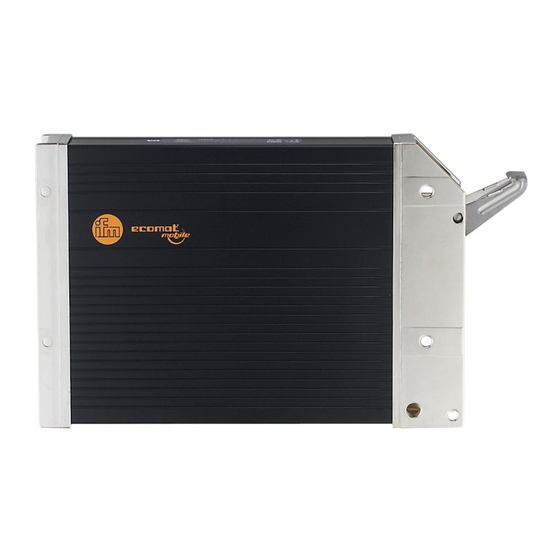
R 360 STARTER 2. Hardware 2.1 Steuerung ecomat R 360 Die frei programmierbaren Steuerungen der Typenreihe R 360 wurden speziell für den Einsatz in Fahrzeugen bzw. in mobilen Anwendungen entwickelt. Zusammen mit anderen Komponenten des Steuerungssystems ecomat 100 bilden diese ein System zur Steuerung und Überwachung dieser Maschinen. Im Gegensatz zu herkömmlichen Industriesteuerungen für den Einsatz im geschützten Schaltschrank, werden die Steuerungen R 360 den extremen Anforderungen für diesen Einsatzbereich gerecht. -
Page 7: I/O-Simulatorbox
R 360 STARTER 2.2 I/O-Simulatorbox Zum Testen der beigefügten oder selbsterstellten Projekt-Applikationen ist die I/O-Simulatorbox ausgestattet mit ... 4 Miniatur-Kippschalter zur Simulation der Digitaleingänge (Ein / Aus / Taster Ein) 1 Potentiometer, 10 kΩ linear, zur Simulation eines Analogeingangs 4 Glimmlampen, gelb, zur Simulation der Ausgänge Betriebsspannung [V ] der I/O-Simulatorbox: 10 ... -
Page 8: Kommunikations-Schnittstellen
R 360 STARTER 2.3 Kommunikations-Schnittstellen RS 232 Pin 1: n.c. Pin 6: n.c. Pin 2: TxD Pin 7: n.c. Pin 3: RxD Pin 8: n.c. Pin 4: n.c. Pin 9: n.c. Pin 5: GND CAN-Bus Pin 1: GND Pin 2: VBB Pin 3: CAN-GND Pin 4: CAN-H Pin 5: CAN-L... -
Page 9: Software (Cd-Rom)
R 360 STARTER 3. Software (CD-ROM) plus 3.1 Programmiersoftware ecolog 100 plus ecolog100 ist eine komplette Entwicklungsumgebung für ecomat R 360 Steuerungen. Sie ermöglicht dem SPS-Programmierer einen komfortablen Ein- stieg in die umfangreichen Sprachmittel gemäß IEC 61131-3. plus Im Überblick bietet ecolog100 folgende Funktionen und Merkmale: Programmierung der Steuerung nach Norm IEC 61131-3. -
Page 10: Installation
R 360 STARTER 4. Installation EITE... -
Page 11: Hardware
R 360 STARTER 4.1 Hardware Verbinden Sie den 55-poligen AMP-Stecker mit der Steuerung. Beachten Sie hierbei die Schrittfolge der Prinzipzeichnung: A: Setzen Sie den AMP-Stecker in die Führungsnut der Steuerung. B: Schwenken Sie den AMP-Stecker auf den Stecker der Steuerung. (Die Führungsnut fixiert den AMP-Stecker und dient als Drehpunkt) C: Legen Sie den Verriegelungsbügel über den AMP-Stecker. -
Page 12: Installierte Software
R 360 STARTER 4.3 Installierte Software Nach der Installation befinden sich folgende Verzeichnisse bzw. Dateien auf Ihrer Festplatte: C:\ECOP_21 plus Programm „ecolog100 “ (incl. Hilfsdateien und Deinstall-Programmdatei) C:\ECOP_21\LIB Enthält allgemeine Bibliotheken C:\ECOP_21\LIB\CR0501_K Enthält gerätespezifischen Dateien C:\ECOP_21\PROJEKTE Enthält Projektbeispiele Bitte beachten: Verzeichnissstruktur und -namen sollten nachträglich nicht geändert werden. -
Page 13: Erste Schritte
R 360 STARTER 5. Erste Schritte plus 5.1 Programm „ecolog 100 “ starten Wählen Sie in der Menüleiste „Start“ „Programme“ „ecolog100plus 2.1“ „ecoplus“ 5.2 Kommunikationsparameter Das Installationsprogramm nimmt keine Änderungen an Ihrer Schnittstellen- plus konfiguration vor. Überprüfen Sie deshalb im Programm „ecolog100 “... -
Page 14: Technische Daten
R 360 STARTER 6. Technische Daten 6.1 CR0501 Gehäuse geschlossenes, abgeschirmtes Metallgehäuse mit Flanschbefestigung Maße Gehäuse 225 x 153 x 43 mm (BxHxT), ohne Anschlußstecker 240 x 153 x 43 mm (BxHxT), mit Anschlußstecker Einbaulage Vorzugsweise senkrecht stehend, alternativ waagerecht liegend Geräteanschluß... - Page 15 R 360 STARTER Binärer Eingang Low-Side ≥ 10 V; I ≥ 3,3 mA Eingänge Einschaltpegel ≤ 5 V; I ≤ 1,7 mA IX0.04 .. .IX0.07 Ausschaltpegel Eingangsfrequenz 50 Hz ; I ≥ 6,7 mA Eingänge IX0.08 ... IX0.23 Einschaltpegel 0,6 U ...
-
Page 16: Maßzeichnung
R 360 STARTER Ausgang Error Halbleiterausgang; kurzschluß- und überlastfest Schaltspannung 11 ... 32V Schaltstrom 10 mA ... 100 mA Überlaststrom 0,5 A Relais-Ausgang Interner Relais-Ausgang Schließerkontakt in Reihe zu (max. 12) Halbleiteraus- gängen für potentialgetrennte Abschaltung. Zwangssteuerung durch Hardware und zusätzliche Steuerung durch Anwenderprogramm (näheres siehe Hardwarebeschreibung, Kapitel 2 des Systemhand- buchs.). -
Page 17: Betriebsanzeige Der Steuerung
R 360 STARTER 6.3 Betriebsanzeige der Steuerung Nach dem Anlegen der Versorgungsspannung kann sich die Steuerung in einem von 5 möglichen Betriebszuständen befinden: Reset Die Status-LED leuchtet kurzzeitig orange. Dieser Zustand wird nach jedem Power-On-Reset durchlaufen. Das Betriebs- system wird initialisiert. Verschiedene Checks werden durchgeführt. Dieser temporäre Zustand wird vom Run-Zustand abgelöst. -
Page 18: Anschlussbelegung
R 360 STARTER 6.4 Anschlussbelegung CR0501 Supply Supply GND Output +24 V Output +24 V Supply +24 V Output GND Input %IW9 0 ... 10 V DC %IW10 Relais 10 Bit, 50 kΩ %IW11 %IW12 %IX0.04 %IX0.04 %IX0.04 %IX0.04 %IX0.04 %IX0.05 %IX0.06 %IX0.07... -
Page 19: Wartung, Instandsetzung, Entsorgung
R 360 STARTER Verwendete Abkürzungen: = analog = binär = binär high-side = binär low-side = CAN-Schnittstelle = CAN-Schnittstelle = Eingang für Drehgebersignale = Eingang für Frequenzmessung = Impuls high-side = Impuls low-side = Last = PWM high-side = PWM low-side = Ausgang für Puls-weiten-modulierte Signale = Rücklesekanal = serielle Schnittstelle (Empfangsdaten) - Page 20 The program ecolog100 has been specifically developed for the control systems of ifm electronic gmbh. It therefore only functions with these controllers. Attempts to use it with systems from other manufacturers can lead to serious damage.
- Page 21 R 360 STARTER SET Contents General 1.1 Function and features page 23 1.2 Components of the starter set page 23 1.3 System requirements page 23 Hardware 2.1 Controller ecomat R 360 page 24 2.2 I/O simulator box page 25 2.3 Communication interfaces page 26 2.4 Voltage supply page 26...
- Page 22 R 360 STARTER SET Safety instructions Observe the information of the description. Non-observance of the notes, operation which is not in accordance with use as prescribed below, wrong installation or handling can result in serious harm concerning the safety of people and plants.
-
Page 23: General
R 360 STARTER SET 1. General 1.1 Function and features The starter set for the control system ecomat 100 type R 360 is used to test plus the ifm application software ecolog 100 . Hardware and software can be easily installed. All required connections are prewired. Please note: Use in conjunction with controllers from other manufacturers can lead to destruction of the controller or the I/O simulator box. -
Page 24: Hardware
R 360 STARTER SET 2. Hardware 2.1 Controller ecomat R 360 The programmable controllers series R 360 have been specifically developed for use in vehicles or mobile applications. In conjunction with the other com- ponents of the control system ecomat 100 they are used to control and moni- tor these mobile machines. -
Page 25: I/O Simulator Box
R 360 STARTER SET 2.2 I/O simulator box To test the supplied or self-made project applications the I/O simulator box contains ... 4 miniature switches to simulate the digital inputs (on / off / momentary on) 1 potentiometer, 10 kΩ linear to simulate the analog input 4 yellow lamps to simulate the outputs Operating voltage [V ] of the I/O simulator box: 10 ... -
Page 26: Communication Interfaces
R 360 STARTER SET 2.3 Communication interfaces RS 232 Pin 1: n.c. Pin 6: n.c. Pin 2: TxD Pin 7: n.c. Pin 3: RxD Pin 8: n.c. Pin 4: n.c. Pin 9: n.c. Pin 5: GND CAN-Bus Pin 1: GND Pin 2: VBB Pin 3: CAN-GND Pin 4: CAN-H... -
Page 27: Software (Cd-Rom)
R 360 STARTER SET 3. Software (CD-ROM) plus 3.1 Programming software ecolog 100 plus ecolog100 is a complete development environment for ecomat R360 con- trollers. With this environment the PLC programmer can conveniently use the programming languages to IEC 61131-3. plus Functions and features of ecolog100 Programming of the controller to the standard IEC 61131-3... -
Page 28: Installation
R 360 STARTER SET 4. Installation step A RS 232 D-SUB (9 poles) 24 V DC connector (2 poles) CAN bus socket (5 poles) I/O simulator box step B step C PAGE... -
Page 29: Hardware
R 360 STARTER SET 4.1 Hardware Connect the 55-pole AMP connector to the controller. Proceed as shown on the schematic drawing: A: Place the AMP connector into the guiding slot of the controller. B: Swivel the AMP connector onto the connector of the controller. (the guiding slot fixes the AMP connector and serves as a pivot) C: Place the locking clip over the AMP connector. -
Page 30: Installed Software
R 360 STARTER SET 4.3 Installed software After installation the following directories or files are on your hard disk: C:\ECOP_21EG plus Program „ecolog100 “ (incl. help files and deinstall program file). C:\ECOP_21EG\LIB Contains general libraries. C:\ECOP_21EG\LIB\CR0501_K Contains controller-specific files. C:\ECOP_21EG\PROJEKTE Contains project examples. -
Page 31: First Steps
R 360 STARTER SET 5. First steps plus 5.1 Start the program "ecolog 100 " In the menu bar select "Start" "Programs" "ecolog100plus 2.1 EG" "ecoplus EG" 5.2 Communication parameters The installation program does not change your interface configuration. So check the communication parameters of the serial interface you use (COM1 plus or COM2) in the program "ecolog100... -
Page 32: Technical Data 6.1 Cr0501
R 360 STARTER SET 6. Technical data 6.1 CR0501 Housing enclosed, shielded metal housing with flange fixing Dimensions of the Housing 225 x 153 x 43 mm (WxHxD) without connector 240 x 153 x 43 mm (WxHxD) with connector Mounting position preferably vertical as an alternative horizontal Device connection... - Page 33 R 360 STARTER SET ≥ 10 V; I ≥ 3.3 mA Binary input low side switch-on level ≤ 5 V; I ≤ 1.7 mA Inputs switch-off level IX0.04 .. .IX0.07 input frequency 50 Hz ; I ≥ 6.7 mA switch-on level 0.6 U ...
-
Page 34: Scale Drawing
R 360 STARTER SET Output error semiconductor output, short-circuit and overload protected switching voltage 11 ... 32V switching current 10 mA ... 100 mA overload current 0.5 A Relay output internal relay output NO contact in series to (max. 12) semiconductor out- puts the power supply of which is interrupted on detection of an error by hardware or user program (details are given in the hardware description section 2... -
Page 35: Status Led Of The Controller
R 360 STARTER SET 6.3 Status LED of the controller After power on the controller can be in one of 5 possible operating states: Reset The status LED briefly lights orange. With each power-on reset the following procedure is carried out. The operat- ing system is initialised. -
Page 36: Pin Connection
R 360 STARTER SET 6.4 Pin connection CR0501 Supply Supply GND Output +24 V Output +24 V Supply +24 V Output GND Input %IW9 0 ... 10 V DC %IW10 Relais 10 Bit, 50 kΩ %IW11 %IW12 %IX0.04 %IX0.04 %IX0.04 %IX0.04 %IX0.04 %IX0.05... -
Page 37: Maintenance, Repair And Disposal
R 360 STARTER SET Abbreviations used: = analog = binary = binary high side = binary low side = CAN interface = CAN interface = input for encoder signals = input for frequency measurement = pulse high side = pulse low side = load = PWM high side = PWM low side... -
Page 38: Notizen
R 360 STARTER SET Notizen / Notes PAGE... - Page 39 R 360 STARTER SET PAGE...
- Page 40 Sachnr. 7390250/04 08/2001 Technische Änderungen behalten wir uns ohne vorherige Ankündigung vor. Papier chlorfrei gebleicht.
Need help?
Do you have a question about the Ecomat 100 R360 and is the answer not in the manual?
Questions and answers