Sign In
Upload
Manuals
Brands
IFM Electronic Manuals
Controller
ecomot 300 AC1355
IFM Electronic ecomot 300 AC1355 Manuals
Manuals and User Guides for IFM Electronic ecomot 300 AC1355. We have
1
IFM Electronic ecomot 300 AC1355 manual available for free PDF download: Supplementary Device Manual
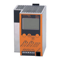
IFM Electronic ecomot 300 AC1355 Supplementary Device Manual (169 pages)
AS-i controllere with Ethernet programming interface
Brand:
IFM Electronic
| Category:
Controller
| Size: 1.36 MB
Table of Contents
Table of Contents
3
1 On this Manual
9
What Do the Symbols and Formats Stand for
9
Warning Levels, Signal Words
9
Symbols and Formats
9
What Devices Are Described in this Manual
10
How Is this Manual Structured
10
Overview: Where Is What
11
2 Safety Instructions
13
General
13
What Previous Knowledge Is Required
13
Functions and Features
13
3 System Requirements
15
Information Concerning the Device
15
Information Concerning the Software
15
Required Accessories
15
4 Function
17
Overview
17
Data Management
18
Which Operating Modes Are There for the PLC in the Controller E
19
AS-Interface as Well as Project Transmission and Diagnosis Via RS232
19
Project Transmission and Diagnosis Via Ethernet Interface
20
Point-To-Point Connection
20
Overview Point-To-Point Connection
20
Step 1: Connect the PC to the Controller E
21
Step 2: Set IP Addresses and Subnet Mask
21
Step 3: Select the Target System and Write the Project
25
Step 4: Set the Communication Parameters
27
Step 5: Transmit and Start the Project
29
Step 6: Set-Up, Monitoring and Diagnosis of the AS-I System
30
Step 7: Create the Boot Project and Save the Source Code
31
Step 8: Transmit the Source Code from the Controller E to the PC (Service Case)
32
Ethernet Network Connection
34
Overview Ethernet Network Connection
34
Excursion: Global Network Variables / EXP Files
35
Overview: Steps for Implementing an Ethernet Network Connection
36
Step 1: Connect the Devices Via Ethernet
36
Step 2: Set IP Addresses and Subnet Mask
36
Step 3: Select the First Target System and Create a Project
37
Step 4: Set the Communication Parameters
39
Step 5: Activate the Network Variable Support
41
Step 6: Integrate Libraries
42
Step 7: Complete and Transmit the Project (Global Network Variables)
43
Excursion: Variable List Identifier (COB ID)
45
Continuation of Step 7
46
Step 8: Write Projects for Further Controller E Devices
46
Step 9: Transmit Projects
48
Step 10: Test the Global Network Variable Transmission
48
MODBUS/TCP Server / Client
49
Overview MODBUS/TCP Server / Client
49
Valid Modbus Addresses and Their Meaning
50
Modbus Address for Controller E PLC Status
52
Modbus Address for Modbus Timeout
52
Modbus Address for Modbus Write Timeout
52
Modbus Address for "Delete Modbus Write Timeout Register
52
Modbus Addresses of the Digital Slave Inputs and Outputs
53
IEC Addresses in the PLC of the Controller E for the Digital Slave Inputs and Outputs
54
Modbus Addresses for the Master Flags
56
IEC Addresses in the PLC of the Controller E for the Master Flags
56
Modbus Addresses for the Analogue Slave Inputs and Outputs
57
Status Information of Analogue Slaves
61
IEC Addresses in the PLC of the Controller E for the Analogue Slave Inputs and Outputs
63
Modbus Addresses for Configuration Data (CDI) of the Slaves
69
IEC Addresses in the PLC of the Controller E for Configuration Data (CDI) of the Slaves
70
Modbus Addresses for Parameter Data of the Slaves
71
IEC Addresses in the PLC of the Controller E for Parameter Data of the Slaves
71
Modbus Addresses for the Slave List las (List of Active Slaves)
72
IEC Addresses in the PLC of the Controller E for the Slave List las (List of Active Slaves)
72
Modbus Addresses for the Slave List LDS (List of Detected Slaves)
73
IEC Addresses in the PLC of the Controller E for the Slave List LDS (List of Detected Slaves)
73
Modbus Addresses for the Slave List LPF (List of Slaves with Periphery Faults)
74
IEC Addresses in the PLC of the Controller E for the Slave List LPF (List of Slaves with Periphery Faults)
74
Modbus Addresses for the Slave List LPS (List of Projected Slaves)
75
IEC Addresses in the PLC of the Controller E for the Slave List LPS (List of Projected Slaves)
75
Modbus Addresses for the Slave Telegram Error Counters
76
IEC Addresses in the PLC of the Controller E for the Slave Telegram Error Counter
77
Modbus Addresses for the Configuration Error Counter
78
Modbus Addresses for the Request Data of the Host Command Channel
79
Modbus Addresses for the Response Data of the Host Command Channel
80
Modbus Addresses for the Fieldbus Data From/To the PLC of the Controller E
81
Modbus Addresses for the Extended Data From/To the PLC of the Controller E
83
IEC Addresses in the PLC of the Controller E for the Extended Data From/To the PLC of the Controller E
89
Data Exchange HTML Page - Controller E
90
Overview HTML Data Exchange
90
Setting up an Own Web Page
91
Step 1: Connect the Devices Via Ethernet
91
Step 2: Set IP Addresses and Subnet Mask
91
Step 3: Open the HTML Page in the Browser
92
Step 4: Address the File Server Via FTP
93
Functions Available in the Applet
95
Step 5: Edit the Web Page
95
Call the Function Cyclically
96
Step 6: Loading and Testing the Modified Web Page
97
5 Menu
99
Menu "Ethernet Setup
99
6 Operation
101
The Modbus Command Channel
101
Request from Host
101
Response from Controller E
101
Overview of the Commands in the Modbus Command Channel
102
Command 0 (0#00): no Execution of a Command
104
Request from Host
104
Response from Controller E
104
Command 1 (0#01): Write Parameters to a Connected AS-I Slave
105
Request from Host
105
Response from Controller E in the Normal Case
105
Possible Error Codes
106
Response from Controller E in the Case of an Error
106
Request from Host
107
Response from Controller E in the Normal Case
107
Possible Error Codes
108
Response from Controller E in the Case of an Error
108
Command 4 0#04): List of the Projected AS-I Slaves (LPS)
109
Request from Host
109
Response from Controller E in the Normal Case
109
Response from Controller E in the Case of an Error
110
Possible Error Codes
110
Command 5 (0#05): Set the Operating Mode of the AS-I Master
111
Request from Host
111
Response from Controller E in the Normal Case
111
Response from Controller E in the Case of an Error
111
Possible Error Codes
111
Command 6 (0#06): Readdress a Connected AS-I Slave
112
Request from Host
112
Response from Controller E in the Normal Case
112
Response from Controller E in the Case of an Error
113
Possible Error Codes
113
Command 7 (0#07): Set the Auto Address Mode of the AS-I Master
114
Request from Host
114
Response from Controller E
114
Command 9 (0#09): Change the Extended ID Code 1 in the Connected AS-I Slave
115
Request from Host
115
Response from Controller E in the Normal Case
115
Response from Controller E in the Case of an Error
116
Possible Error Codes
116
Request from Host
117
Directly to / from 3 AS-I Slaves in each Case
117
Response from Controller E
119
Request from Host
121
Response from Controller E in the Normal Case
121
Command 21 (0#15): Read the ID String of an AS-I Slave with Profile S-7.4
121
Response from Controller E in the Case of an Error
123
Possible Error Codes
123
Command 28 (0#1C): Deactivate the Slave Reset When Changing to the Protected Mode
124
Request from Host
124
Response from Controller E
124
Request from Host
125
Response from Controller E in the Normal Case
125
Response from Controller E in the Case of an Error
128
Possible Error Codes
128
Request from Host
131
Response from Controller E
131
Profile S-7.4
131
Request from Host
133
Response from Controller E
134
CTT2 Profile (S-7.5.5, S-7.A.5 or S-B.A.5)
135
Request from Host
135
Possible CTT2 Error Codes
138
Possible Error Codes
138
Response from Controller E in the Case of an Error (Error Detected by AS-I Slave)
138
Request from Host
139
Response from Controller E in the Normal Case
140
Possible Error Codes
141
Response from Controller E in the Case of an Error (Error Detected by AS-I Master)
141
Possible CTT2 Error Codes
142
Response from Controller E in the Case of an Error (Error Detected by AS-I Slave)
142
Command 38 (0#26): Acyclic Manufacturer-Specific Read Call to an AS-I Slave with CTT2 Profile (S-7.5.5, S-.7.A.5 or S-B.A.5)
143
Request from Host
143
Response from Controller E in the Normal Case
144
Response from Controller E in the Case of an Error (Error Detected by AS-I Master)
145
Possible Error Codes
146
Response from Controller E in the Case of an Error (Error Detected by AS-I Slave)
146
Possible CTT2 Error Codes
146
Request from Host
147
To an AS-I Slave with CTT2 Profile (S-7.5.5, S-7.A.5 or S-B.A.5)
147
Response from Controller E in the Normal Case
148
Possible Error Codes
149
Response from Controller E in the Case of an Error (Error Detected by AS-I Master)
149
Possible CTT2 Error Codes
150
Response from Controller E in the Case of an Error (Error Detected by AS-I Slave)
150
Request from Host
151
Response from Controller E
151
Command 54 (0#36): Read Current Parameters of a Connected AS-I Slave
152
Request from Host
152
Response from Controller E
152
Command 55 (0#37): Read Current AS-I Slaves
154
Request from Host
154
Response from Controller E
154
Command 56 (0#38): Read Projected Configuration of the AS-I Slaves 1(A)
156
Response from Controller E
156
Command 96 (0#60): Save Data Non-Volatilely in the Flash Memory of the Controller E
157
Request from Host
157
Response from Controller E
157
Command 97 (0#61): Carry out Various Settings in the Controller E
158
Request from Host
158
Response from Controller E
158
Command 102 (0#66): Retrieve the Status of the Controller E Display
159
Request from Host
159
Response from Controller E
159
Command 105 (0#69): Read the Device Properties of the Controller E
161
Request from Host
161
Response from Controller E
161
7 Terms, Abbreviations
163
8 Index
169
Advertisement
Advertisement
Related Products
IFM Electronic ecomat 300 AC123 Series
IFM Electronic ecomat 300 AC124 Series
IFM Electronic ecomot 300 AC1353
IFM Electronic ecomot 300 AC1354
IFM Electronic ecomot 300 AC1356
IFM Electronic ecomot 300 AC1357
IFM Electronic ecomot 300 AC1358
IFM Electronic Ecomat 300 AL1010
IFM Electronic Ecomot 100 CR0153
IFM Electronic ecomot100 EC2112
IFM Electronic Categories
Accessories
Measuring Instruments
Controller
Control Unit
Security Sensors
More IFM Electronic Manuals
Login
Sign In
OR
Sign in with Facebook
Sign in with Google
Upload manual
Upload from disk
Upload from URL