Table of Contents
Advertisement
Quick Links
Advertisement
Table of Contents

Related Manuals for IFM Electronic Ecomot 100 CR0153


Summary of Contents for IFM Electronic Ecomot 100 CR0153
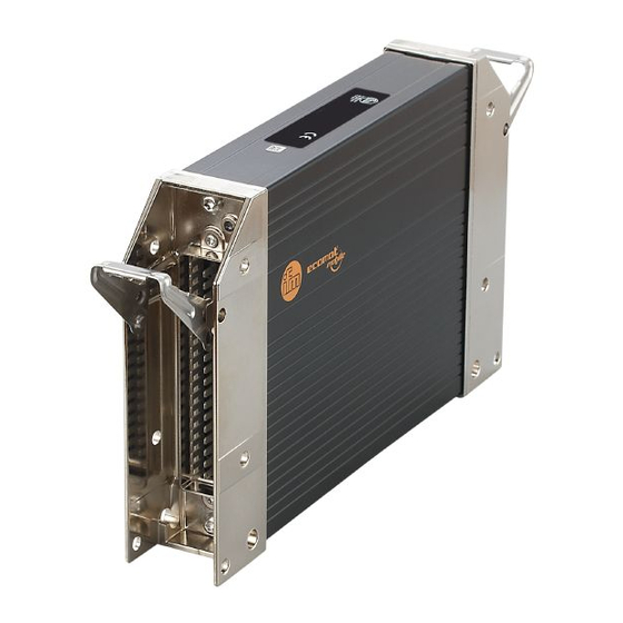
- Page 1 Installation instructions ExtendedController ISOBUS CR0153...
-
Page 2: Table Of Contents
ExtendedController CR0153 Contents 1 Preliminary note � � � � � � � � � � � � � � � � � � � � � � � � � � � � � � � � � � � � � � � � � � � � � � � � � 4 1�1 Symbols used�... - Page 3 ExtendedController CR0153 7 Technical data� � � � � � � � � � � � � � � � � � � � � � � � � � � � � � � � � � � � � � � � � � � � � � � � � � 17 7�1 Mechanical and electric data �...
-
Page 4: Preliminary Note
ExtendedController CR0153 1 Preliminary note This document applies to devices of the type "ExtendedController" (art� no�: CR0153)� It is deemed as a part of the device� This document is intended for specialists� These specialists are people who are qualified by their appropriate training and their experience to see risks and to avoid possible hazards that may be caused during operation or maintenance of the device�... -
Page 5: Safety Instructions
ExtendedController CR0153 2 Safety instructions 2.1 General These instructions are part of the device� They contain information and illustrations about the correct handling of the device and must be read before installation or use� Observe the operating instructions� Non-observance of the instructions, operation which is not in accordance with use as prescribed below, wrong installation or incorrect handling can seriously affect the safety of operators and machinery�... -
Page 6: 2�5 Tampering With The Device
ExtendedController CR0153 2.5 Tampering with the device In case of malfunctions or uncertainties please contact the manufacturer� Tampering with the device can seriously affect the safety of operators and machinery� It is not permitted and leads to the exclusion of any liability and warranty claims�... -
Page 7: Installation
ExtendedController CR0153 4 Installation 4.1 Fixing ► Fix the controller to a flat surface using 4 M5 screws� Screw material: steel or stainless steel Tightening torque: 8 ±2 ► Connect the housing to GND (→ 5.2 Ground connection) NOTE Use screws with a low head to avoid that the connector is damaged when placed and locked�... -
Page 8: 4�3 Mounting Surface
ExtendedController CR0153 4.3 Mounting surface NOTE The housing must not be exposed to any torsional forces or mechanical stress� ► Use compensating elements if there is no flat mounting surface available� Mounting surface 4.4 Heat dissipation ► Ensure sufficient heat dissipation as the internal heating of the electronics is conducted away via the housing�... -
Page 9: Electrical Connection
ExtendedController CR0153 5 Electrical connection 5.1 Wiring Wiring (→ 7 Technical data) Only connect the connector pins as shown in the pin layout� Unspecified connector pins remain unconnected� ► Connect all indicated supply cables and GND terminals (St and Ex connection side)�... -
Page 10: 5�3 Fuses
ExtendedController CR0153 ► Establish a connection between the device and the ground of the vehicle using M5 screws� Screws to be used (→ 4.1 Fixing) 5.3 Fuses ► The individual electric circuits must be protected in order to protect the whole system�... -
Page 11: 5�4�1 Gnd Connections Of The Ex Connection Side
ExtendedController CR0153 ► Basically all supply and signal cables must be laid separately� ► Screen signal cables in EMC critical applications� ► Connect supply and ground cables to the controller and the sensors/actuators via the respective common star point� If a prewired connection cable is used, remove the cores with unused signal inputs and outputs�... -
Page 12: 5�6�1 Unused Input I15
ExtendedController CR0153 5.6.1 Unused input I15 If the input I15 is not used it must be configured as digital input� 5.7 Supply low-side digital outputs (B supply output Q01 load load output Q03 output Q09 load output Q11 load controller Supply low-side digital outputs (B 1: Outputs of the output group VBB 2: Outputs of the output group VBB... -
Page 13: 5�8 Can Wiring St/Ex Side
ExtendedController CR0153 5.8 CAN wiring St/Ex side 5.8.1 Point-to-point wiring CAN 2 CAN n 60 Ω 1� Extended side: CAN2 (with factory pre-configuration) 2� Standard side: CANn (interface selectable) 3� Terminating CAN resistor in the cable 5.8.2 Open CANopen network CAN 2 CAN n 120 Ω... -
Page 14: 5�10 Usb Interface
ExtendedController CR0153 1� Controller (2 x 55-pole connector; USB port on St side) 2� USB connector for programming and service purposes 3� Notebook/PC Connection controller to USB connector, permanent (≤ 3 m). ► Position the USB connector in immediate vicinity to the controller� The cable length "A"... -
Page 15: 6�1 Required Documentation
ExtendedController CR0153 6.1 Required documentation The user can easily create the application program by means of the IEC 61131-3 compliant programming system CODESYS 2�3� In addition to the programming system CODESYS, the following documents are required for programming and commissioning of the controller: ●... -
Page 16: 6�3�1 Install The Usb Drivers
► Start the driver file "USB CR0032 setup vxxxx�exe" and follow the setup instructions� > The driver files and a documentation will be copied to the following directory: C:\Program Files (x86)\ifm electronic\USB_Driver_R360� ► Reboot the PC� ► Connect the controller to a free USB port ►... -
Page 17: Technical Data
CANopen, CiA DS 301 V4.01, CiA DS 306 V1.3 or SAE J 1939 or free protocol ifm electronic gmbh ● Friedrichstraße 1 ● 45128 Essen We reserve the right to make technical alterations without prior notice! CR0153 / page 1... - Page 18 CANopen bus off Note The status LEDs have different levels of brightness ifm electronic gmbh ● Friedrichstraße 1 ● 45128 Essen We reserve the right to make technical alterations without prior notice! CR0153 / page 2 14.06.2016...
-
Page 19: 7�2 Test Standards And Regulations
30 g/6 ms; 24,000 shocks Tests for railway applications EN 50155-12-2: 2007 Electronic equipment used on rolling stock ifm electronic gmbh ● Friedrichstraße 1 ● 45128 Essen We reserve the right to make technical alterations without prior notice! CR0153 / page 3 14.06.2016... -
Page 20: 7�3 St Side / Characteristics Of The Inputs
Voltage input 0...32 V (A) Input resistance 50.7 kΩ Input frequency ≤ 1 kHz (default 35 Hz) ifm electronic gmbh ● Friedrichstraße 1 ● 45128 Essen We reserve the right to make technical alterations without prior notice! CR0153 / page 4 14.06.2016... - Page 21 ± 5% FS: 3...15 kΩ ± 10% FS: 15...30 kΩ Diagnostics > 31 kΩ Short circuit to VBB ifm electronic gmbh ● Friedrichstraße 1 ● 45128 Essen We reserve the right to make technical alterations without prior notice! CR0153 / page 5 14.06.2016...
- Page 22 Frequency / pulse inputs with f xed levels H-bridge function Pulse width modulation Resistor input Supply outputs Supply sensors/module Supply via relay ifm electronic gmbh ● Friedrichstraße 1 ● 45128 Essen We reserve the right to make technical alterations without prior notice! CR0153 / page 6 14.06.2016...
-
Page 23: 7�4 St Side / Characteristics Of The Outputs
≥ 4 Ω / (at 12 V DC) ≥ 8 Ω / (at 24 V DC) Accuracy ± 1.5 % FS ifm electronic gmbh ● Friedrichstraße 1 ● 45128 Essen We reserve the right to make technical alterations without prior notice! CR0153 / page 7 14.06.2016... - Page 24 (valid for all outputs) Short-circuit strength to GND Switch-off of the outputs is carried out via the output driver ifm electronic gmbh ● Friedrichstraße 1 ● 45128 Essen We reserve the right to make technical alterations without prior notice! CR0153 / page 8...
-
Page 25: 7�5 Ex Side / Characteristics Of The Inputs
Short circuit to GND / wire break Voltage on the pin when not ≤ 0.2 V connected ifm electronic gmbh ● Friedrichstraße 1 ● 45128 Essen We reserve the right to make technical alterations without prior notice! CR0153 / page 9 14.06.2016... - Page 26 Input frequency ≤ 30 kHz Switch-on level > 0.35...0.48 U Switch-off level < 0.29 U ifm electronic gmbh ● Friedrichstraße 1 ● 45128 Essen We reserve the right to make technical alterations without prior notice! CR0153 / page 10 14.06.2016...
-
Page 27: 7�6 Ex Side / Characteristics Of The Outputs
Diagnosis short circuit none Digital output (B Switching voltage 8...32 V DC Switching current 0.02...2 A ifm electronic gmbh ● Friedrichstraße 1 ● 45128 Essen We reserve the right to make technical alterations without prior notice! CR0153 / page 11 14.06.2016... - Page 28 (valid for all outputs) Short-circuit strength to GND Switch-off of the outputs is carried out via the output driver ifm electronic gmbh ● Friedrichstraße 1 ● 45128 Essen We reserve the right to make technical alterations without prior notice! CR0153 / page 12...
-
Page 29: 7�7 St Side / Wiring
H-bridge function pulse width modulation pulse width modulation, current-controlled resistor input supply sensors/module supply output group ifm electronic gmbh ● Friedrichstraße 1 ● 45128 Essen We reserve the right to make technical alterations without prior notice! CR0153 / page 13 14.06.2016... -
Page 30: 7�8 Ex Side / Wiring
If not otherwise specif ed, the data apply to the St and Ex side. ifm electronic gmbh ● Friedrichstraße 1 ● 45128 Essen We reserve the right to make technical alterations without prior notice! CR0153 / page 14... -
Page 31: Maintenance, Repair And Disposal
ExtendedController CR0153 8 Maintenance, repair and disposal The device is maintenance-free� ► Do not open the housing as the device does not contain any components which must be maintained by the user� The device must only be repaired by the manufacturer�...
Need help?
Do you have a question about the Ecomot 100 CR0153 and is the answer not in the manual?
Questions and answers