Table of Contents
Advertisement
Quick Links
Advertisement
Table of Contents

Subscribe to Our Youtube Channel
Related Manuals for IFM Electronic SmartController CR2530


Summary of Contents for IFM Electronic SmartController CR2530
- Page 1 Installation instructions SmartController CR2530...
-
Page 2: Table Of Contents
SmartController CR2530 Contents 1 Preliminary note � � � � � � � � � � � � � � � � � � � � � � � � � � � � � � � � � � � � � � � � � � � � � � � � � 4 1�1 Symbols used�... - Page 3 SmartController CR2530 This document is the original instructions� Licences and trademarks All trademarks and company names are subject to the copyright of the respective companies�...
-
Page 4: Preliminary Note
SmartController CR2530 1 Preliminary note This document applies to devices of the type "SmartController" (art� no�: CR2530)� These instructions are part of the device� This document is intended for specialists� These specialists are people who are qualified by their appropriate training and their experience to see risks and to avoid possible hazards that may be caused during operation or maintenance of the device�... -
Page 5: Safety Instructions
SmartController CR2530 2 Safety instructions 2.1 General These instructions are part of the device� They contain texts and figures concerning the correct handling of the device and must be read before installation or use� Observe the operating instructions� Non-observance of the instructions, operation which is not in accordance with use as prescribed below, wrong installation or incorrect handling can seriously affect the safety of operators and machinery�... -
Page 6: 2�5 Tampering With The Device
SmartController CR2530 2.5 Tampering with the device In case of malfunctions or uncertainties please contact the manufacturer� Tampering with the device can seriously affect the safety of operators and machinery� This is not permitted and leads to the exclusion of any liability and warranty claims�... -
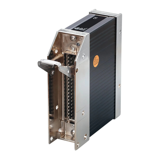
Page 7: Installation
SmartController CR2530 4 Installation 4.1 Fixing ► Fix the controller to a flat surface using 4 M5 screws� Screw material: steel or stainless steel Tightening torque: 8 ±2 NOTE Use screws with a low head to avoid that the connector is damaged when placed and locked�... -
Page 8: 4�3 Mounting Surface
SmartController CR2530 4.3 Mounting surface NOTE The housing must not be exposed to any torsional forces or mechanical stress� ► Use compensating elements if there is no flat mounting surface available� Mounting surface 4.4 Heat dissipation ► Ensure sufficient heat dissipation as the internal heating of the electronics is conducted away via the housing�... -
Page 9: Electrical Connection
SmartController CR2530 5 Electrical connection 5.1 Wiring Wiring (→ 7 Technical data) Only connect the connector pins as shown in the pin layout� Unspecified connector pins remain unconnected� ► Connect all indicated supply cables and GND terminals� 5.2 Ground connection ►... -
Page 10: 5�4 Laying The Supply And Signal Cables
SmartController CR2530 5.4 Laying the supply and signal cables supply sensor input output load sensor input output load controller sensor input output load X = not permissible WARNING The linking of connections in the plug is not permitted and can affect the safety of operators and machinery�... -
Page 11: 5�6 Resistor Inputs
SmartController CR2530 5.6 Resistor inputs supply resistor input resistor input controller Ground return resistor inputs ► Equip each resistor with an own, separated ground return to ensure measurement accuracy� 5.7 Connection technology NOTE Only connect the 55-pole connectors when the supply voltage is disconnected�... -
Page 12: Set-Up
SmartController CR2530 6 Set-up 6.1 Programming The user can easily create the application software by means of the IEC 61131-3 compliant programming system CoDeSys 2�3� 6.2 Required documentation In addition to the CoDeSys programming system, the following documents are required for programming and set-up of the device: ●... -
Page 13: Technical Data
CANopen, CiA DS 301 V4.01, CiA DS 306 V1.3 or SAE J 1939 or free protocol Processor Freescale PowerPC, 50 MHz ifm electronic gmbh ● Friedrichstraße 1 ● 45128 Essen We reserve the right to make technical alterations without prior notice! CR2530 / Page 1 20.09.2013... - Page 14 (STOP) 5 Hz application stopped due to undervoltage permanently on system fault (fatal error) ifm electronic gmbh ● Friedrichstraße 1 ● 45128 Essen We reserve the right to make technical alterations without prior notice! CR2530 / Page 2 20.09.2013...
-
Page 15: 7�2 Test Standards And Regulations
10...500 Hz; 0.72 mm/10 g; 10 cycles/axis ISO 16750-3: 2007 Bumps 30 g/6 ms; 24,000 shocks ifm electronic gmbh ● Friedrichstraße 1 ● 45128 Essen We reserve the right to make technical alterations without prior notice! CR2530 / Page 3 20.09.2013... -
Page 16: 7�3 Input Characteristics
GND / wire break Voltage on the pin when not ≤ 0.2 V connected ifm electronic gmbh ● Friedrichstraße 1 ● 45128 Essen We reserve the right to make technical alterations without prior notice! CR2530 / Page 4 20.09.2013... - Page 17 Input frequency ≤ 30 kHz Switch-on level > 0.35...0.48 U Switch-off level < 0.29 U ifm electronic gmbh ● Friedrichstraße 1 ● 45128 Essen We reserve the right to make technical alterations without prior notice! CR2530 / Page 5 20.09.2013...
-
Page 18: 7�4 Output Characteristics
Diagnosis short circuit none Digital output (B Switching voltage 8...32 V DC Switching current 0.02...2 A ifm electronic gmbh ● Friedrichstraße 1 ● 45128 Essen We reserve the right to make technical alterations without prior notice! CR2530 / Page 6 20.09.2013... - Page 19 (valid for all outputs) Short-circuit strength to GND switch-off of the outputs is carried out via the output driver ifm electronic gmbh ● Friedrichstraße 1 ● 45128 Essen We reserve the right to make technical alterations without prior notice! CR2530 / Page 7...
-
Page 20: 7�5 Wiring
1 supply output group 2 ifm electronic gmbh ● Friedrichstraße 1 ● 45128 Essen We reserve the right to make technical alterations without prior notice! CR2530 / Page 8 20.09.2013... -
Page 21: Maintenance, Repair And Disposal
SmartController CR2530 8 Maintenance, repair and disposal The unit is maintenance-free� ► Do not open the housing as the device does not contain any components which can be repaired by the user� The device must only be repaired by the manufacturer�...
Need help?
Do you have a question about the SmartController CR2530 and is the answer not in the manual?
Questions and answers